Extron electronics FOX3 T 301 Setup Manual
Hide thumbs
Also See for FOX3 T 301:
- User manual (58 pages) ,
- Setup manual (4 pages) ,
- Setup manual (4 pages)
Table of Contents
Advertisement
Quick Links
FOX3 T/R 301 and FOX3 T/R 311 • Setup Guide
This guide provides quick start instructions for an experienced installer to set up and operate the Extron FOX3 T/R 301 and
FOX3 T/R 311 Fiber Optic transmitters and receivers.
WARNING:
The FOX3 T/R 301 and FOX3 T/R 311 outputs continuous invisible light (Class 1 rated), which may be harmful to
the eyes; use with caution. Plug the attached dust caps into the optical transceivers when the fiber cable is unplugged.
CLASS 1 LASER PRODUCT, see the FOX3 T/R 301 and FOX3 T/R 311 User Guide, at www.extron.com.
AVERTISSEMENT :
qui peut être dangereux pour les yeux, à utiliser avec précaution. Branchez les protections contre la poussière dans
l'ensemble émetteur/récepteur lorsque le câble fibre optique est débranché.
Produit laser de classe 1, voir le FOX3 T/R 301 and FOX3 T/R 311 User Guide sur
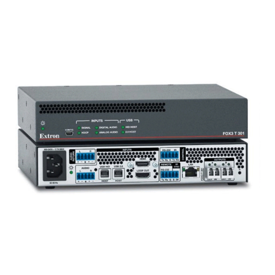
NOTE:
The front and rear panels for the FOX3 T 301 and FOX3 R 301 are shown in this guide. Some of the features on the
FOX3 301 transmitter and receiver are not available on the FOX3 311 transmitter and receiver. See the FOX3 T/R 301 and
FOX3 T/R 311 User Guide at
Installation
Step 1 — Mounting
Turn off or disconnect all equipment power sources and
mount the transmitter as required. For mounting details and
considerations, see the FOX3 T/R 301 and FOX3 T/R 311
User Guide at www.extron.com.
Step 2 — Input and Output Connections
a.
Connect an HDMI video source to the HDMI input (see
H
figure 1 ,
) on the transmitter.
b.
If desired, connect an HDMI video display to the
Loop Out port (
I
) for a local display.
c.
Connect an HDMI display to the HDMI output (
the receiver.
d.
Connect an audio input device to the Audio 5-pole
captive screw port (
to wire the captive screw connector).
e.
Connect an audio output device to the Audio 5-pole
captive screw port (
wire the captive screw connector).
f.
For optional returned audio (
the captive screw connector):
•
Connect an audio output device to the Audio
Return 5-pole captive screw port on the transmitter.
•
Connect an audio input device to the Audio Return
5-pole captive screw port on the receiver.
ATTENTION:
•
For unbalanced audio, connect the sleeves
to the ground contact. DO NOT connect the
sleeves to the negative (–) contacts.
•
Pour l'audio asymétrique, connectez les
manchons au contact au sol. Ne PAS
connecter les manchons aux contacts négatifs
(–).
Le FOX3 T/R 301 and FOX3 T/R 311 émet une lumière invisible en continu (conforme à la classe 1)
www.extron.com
to see the front and rear panels for the FOX3 T 311 and FOX3 R 311.
J
D
) on the transmitter (see figure 2
E
) on the receiver (see figure 2 to
C
) (see figure 2 to wire
~
100-240V
0.7A MAX
L
R
USB HID
AUDIO
L
R
60-60 Hz
A A
A
B B
B
C
C C
D
D D
E E
E
~
100-240V
0.7A MAX
L
R
DEVICES
USB HID
1
1
AUDIO
L
R
2
100 mA
60-60 Hz
A
Power Inlet
) on
B
Power LED
C
Audio Return
D
Audio input (transmitter)
E
Audio output (receiver)
F
USB Host ports
G
USB Hub ports
H
HDMI input (transmitter)
Figure 1.
FOX3 T/R 301 Rear Panels
Tip
Sleeve
Tip
Sleeve
Unbalanced Stereo Input
No Ground Here
Tip
Sleeves
Tip
No Ground Here
Unbalanced Stereo Output
Figure 2.
Audio Wiring Diagrams
www.extron.com
(en anglais).
INPUTS
RS-232
IR
HDMI
Tx Rx
G
Tx Rx
REMOTE
3D
LAN
USB 2.0
SYNC
RS-232
LOOP OUT
HOST
HOST
Tx Rx
G
S 5V
J
F
F F
G G
G
H
H H
I
I I
J
J J
K K
K
M M
M
L L
L
OUTPUTS
RS-232
IR
Tx Rx
G
Tx Rx
REMOTE
3D
LAN
SYNC
USB 2.0
RS-232
1
500 mA
HDMI
Tx Rx
G
S 5V
I
HDMI Loop Out
J
HDMI output (receiver)
K
Remote RS-232/3D Sync port
L
Control RS-232/IR port
M
LAN Ethernet port
N
SFP module and LEDs
O
Reset button
Tip
Ring
Sleeves
Tip
Ring
Balanced Stereo Input
Tip
Ring
Sleeves
Tip
Ring
Balanced Stereo Output
OUTPUTS
A
B
R
OUT
IN
OUT
IN
N
N N
O
O O
INPUTS
A
B
R
OUT
IN
OUT
IN
Do not tin the wires!
1
Advertisement
Table of Contents

Related Manuals for Extron electronics FOX3 T 301


Summary of Contents for Extron electronics FOX3 T 301
- Page 1 NOTE: The front and rear panels for the FOX3 T 301 and FOX3 R 301 are shown in this guide. Some of the features on the FOX3 301 transmitter and receiver are not available on the FOX3 311 transmitter and receiver. See the FOX3 T/R 301 and www.extron.com...
- Page 2 FOX3 T/R 301 and FOX3 T/R 311 • Setup Guide (Continued) Connect peripheral devices to the USB ports (see figure 3) . NOTES: • The FOX3 matrix switches the USB HID and USB 2.0 inputs and outputs independently of the video and each USB connection.
- Page 3 HID HOST CONFIG firmware via PCS or internal web pages. HDCP ANALOG AUDIO 2.0 HOST FOX3 T 301 Inputs LEDs — Signal LED — Lights when the unit detects an input • video signal. • HDCP LED — Lights when the input signal is HDCP INPUT encrypted.
- Page 4 For information on safety guidelines, regulatory compliances, EMI/EMF compatibility, accessibility, and related topics, see the Extron Safety and Regulatory Compliance Guide on the Extron website. www.extron.com © 2020 Extron Electronics — All rights reserved. 68-2711-50 Rev. A All trademarks mentioned are the property of their respective owners. 02 20...
Need help?
Do you have a question about the FOX3 T 301 and is the answer not in the manual?
Questions and answers