Table of Contents
Advertisement
Quick Links
FOXBOX HDMI • Setup Guide
This guide provides quick start instructions for an experienced installer to set up and operate the Extron FOXBOX HDMI fiber optic
extenders.
CLASS 1 LASER PRODUCT, see
CAUTION:
•
These units output continuous invisible light, which may be harmful to the eyes; use with caution. For additional safety, plug the
attached dust caps into the optical transceivers when the fiber optic cable is unplugged.
•
Ces produits émettent une lumière invisible continue, qui peut être dangereuse pour les yeux ; à utiliser avec précaution. Pour
une sécurité renforcée, associez les bouchons anti-poussière à l'ensemble émetteur/récepteur optique lorsque le câble fibre
optique est débranché.
Installation
Step 1 — Mounting
Turn off or disconnect all equipment power
sources and mount the transmitter and
receiver as required.
Step 2 — Input and Output
Connections
a.
Connect an HDMI video source to the
transmitter HDMI connector.
b.
If desired, connect an HDMI video display to the transmitter HDMI Loop-Thru connector.
c.
Connect an HDMI video display to the receiver HDMI Output connector.
NOTE:
Use a LockIt™ Lacing Bracket to
1.
Plug the HDMI cable into the panel connection
2.
Loosen the HDMI connection mounting screw from the panel enough to allow the
LockIt lacing bracket to be placed over it. The screw does not have to be removed.
3.
Place the LockIt lacing bracket on the screw and against the HDMI connector, then
tighten the screw to secure the bracket.
ATTENTION:
•
Do not overtighten the HDMI connector mounting screw. The shield it
fastens to is very thin and can easily be stripped.
•
Ne serrez pas trop la vis de montage du connecteur HDMI. Le blindage
auquel elle est attachée est très fin et peut facilement être dénudé.
4.
Loosely place the included tie wrap around the HDMI connector and the LockIt lacing
bracket as shown.
5.
While holding the connector securely against the lacing bracket, use pliers or similar tools to tighten the tie wrap, then
remove any excess length.
d.
Connect an audio input device to the transmitter Input Audio 3.5 mm mini jack.
e.
Connect an audio device to the receiver Audio captive
screw connector. See the drawing at right.
ATTENTION:
•
For unbalanced audio, connect the sleeves to the ground contact. DO NOT connect the sleeves to the negative (-) contacts.
Pour l'audio asymétrique, connectez les manchons au contact au sol. NE PAS connecter les manchons aux
•
contacts négatifs (–).
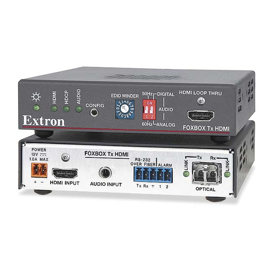
FOXBOX HDMI
User Guide at
POWER
FOXBOX Tx HDMI
12V
1.0A MAX
AUDIO INPUT
HDMI INPUT
FOXBOX Tx HDMI Rear Panel
POWER
Tx
Rx
12V
1.0A MAX
OPTICAL
FOXBOX Rx HDMI Rear Panel
securely fasten an HDMI cable to each device as follows
www.extron.com
Tx
Rx
RS-232
OVER FIBER ALARM
Tx Rx
1
2
OPTICAL
Front Panel
HDMI AUDIO
ON
FOXBOX Rx HDMI
HDMI
OFF
NO GROUND HERE
Tip
Sleeves
Tip
NO GROUND HERE
Do not tin the wires!
Unbalanced Stereo Output
50Hz
DIGITAL
Edid MINDER
CONFIG
AUDIO
60Hz
ANALOG
OUTPUTS
AUDIO
RS-232
L
R
OVER FIBER ALARM
Tx Rx
1
2
.
3
2
1
3
4
5
Tip
Ring
Sleeves
Tip
Ring
Balanced Stereo Output
HDMI LOOP THRU
FOXBOX Tx HDMI
REMOTE
RS-232
Tx Rx
1
Advertisement
Table of Contents

Related Manuals for Extron electronics FOXBOX HDMI


Summary of Contents for Extron electronics FOXBOX HDMI
- Page 1 FOXBOX HDMI • Setup Guide This guide provides quick start instructions for an experienced installer to set up and operate the Extron FOXBOX HDMI fiber optic extenders. FOXBOX HDMI www.extron.com CLASS 1 LASER PRODUCT, see User Guide at CAUTION: •...
- Page 2 FOXBOX HDMI • Setup Guide (Continued) If you want the FOXBOX HDMI units to pass serial data or control signals, such as for serial control of a RS-232 OVER FIBER ALARM projector, connect the primary device to the transmitter and the slave device to the receiver via the left three poles (Tx, Rx, ) of the RS-232 Over Fiber/Alarm 5-pole captive screw connectors on both units.
- Page 3 Indications Tx Link and Rx Link LEDs — When lit, the link is active (light is output [Tx] or received [Rx]). OPTICAL Tx Rx NOTE: The Link LEDs indicate transmission of light only, not whether there is data encoded in the optical link Power LED —...
- Page 4 For information on safety guidelines, regulatory compliances, EMI/EMF compatibility, accessibility, and related topics, see the Extron Safety and Regulatory Compliance Guide on the Extron website. www.extron.com © 2012-2020 Extron — All rights reserved. 68-1984-50 Rev. B All trademarks mentioned are the property of their respective owners. 10 20 Worldwide Headquarters: Extron USA West, 1025 E.
Need help?
Do you have a question about the FOXBOX HDMI and is the answer not in the manual?
Questions and answers