Advertisement
Quick Links
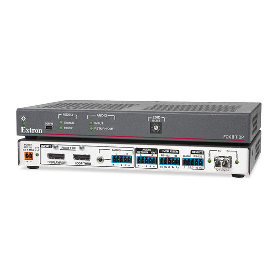
FOX II T/R DP • Setup Guide
This guide provides quick start instructions for an experienced installer to set up and operate
the Extron FOX II T/R DP fiber optic extenders.
WARNING
: Vision hazard — This unit outputs continuous laser light, which may be harmful to the eyes; use with caution. For
additional safety, plug the attached dust caps into the optical transceivers when the fiber optic cable is unplugged.
CLASS 1 LASER PRODUCT, see the FOX II T/R DP User Guide, available at www.extron.com.
Installation
Step 1 — Mounting
Turn off or disconnect all equipment power sources
and mount the transmitter and receiver as required.
ATTENTION: This unit is very warm in operation.
Allow proper spacing for ventilation
Step 2 — Input and Output Connections
a.
Connect a DisplayPort video source to the transmitter DisplayPort input connector.
b.
If desired, connect a DisplayPort video display to the transmitter Loop-Thru connector for a local display.
c.
Connect a DisplayPort video display to the receiver DisplayPort output connector.
d.
Connect an audio input device to either the Audio 3.5 mm mini jack or the Audio 5-pole captive screw connector on
the transmitter. See the drawing to the right of step 2g to make connections on the captive screw connector.
e.
For optional returned audio, connect an audio output device to the Audio Return Out 5-pole captive screw connector
on the transmitter. See the drawing to the right of step 2g to make connections on the captive screw connector.
f.
Connect an audio output device to either or both the 3.5 mm mini jack or the Audio 5-pole captive screw connector on
the receiver. See the drawing below right to make connections on the captive screw connector.
For optional returned audio, connect an audio input device
g.
to the Audio Return In 5-pole captive screw connector on the
receiver. See the drawing above to make connections on the
captive screw connector.
AUDIO
ATTENTION: For unbalanced audio output, connect the
RETURN
IN
L
R
NOTE: For returned audio, above, and RS-232 and IR responses (from the receiver to the transmitter), below, you must install the
Receiver-Tx-to-transmitter-Rx cable in
Mode
on the next page).
h.
If you want the FOX II DP units to pass serial or IR data or control signals, such as for serial control of a projector,
connect the primary device to the transmitter and the secondary device to the receiver via the Over Fiber 5-pole captive
screw connectors on both units.
i.
For remote monitoring of the status of the Rx optical link on either the transmitter or receiver, connect a locally
constructed or obtained device to the two left Alarm poles of the Alarm and Remote RS-232 5-pole captive screw
connector on that unit. The unit shorts both poles together when no light is detected.
NOTE: The transmitter port reports the status of the link from the receiver.
The receiver port reports the status of the link from the transmitter.
j.
For remote control of a unit and loading firmware, connect a host device, such as a computer or control system, to
either of the following ports on the unit to be controlled:
Configuration port — A front panel mini USB connector.
Remote RS-232 port — The rear panel Remote RS-232 3-pole captive screw connector. The protocol for the Remote
port is as follows:
•
9600 baud
1 stop bit
•
sleeves to the ground contact. DO NOT connect the
sleeves to the negative (–) contacts.
step 3b
•
no parity
•
no flow control
•
POWER
INPUTS
FOX II T DP
12V
1.2 A MAX
DISPLAYPORT
LOOP THRU
FOX II DP Transmitter Rear Panel
FOX II R DP
POWER
OUTPUTS
12V
1.2 A MAX
DISPLAYPORT
FOX II DP Receiver Rear Panel
Do not tin the wires!
and leave the receiver in the return link (default) configuration (see
8 data bits
AUDIO
OVER FIBER
AUDIO
RETURN
OUT
L
R
L
R
RS-232
IR
ALARM
Tx Rx
G
Tx Rx
1
2
AUDIO
OVER FIBER
AUDIO
RETURN
IN
IR
L
R
L
R
RS-232
ALARM
Tx Rx
G
Tx Rx
1
2
Tip
Ring
Tip
Sleeve
Sleeves
Tip
Tip
Sleeve
Ring
Unbalanced Stereo Input
No Ground Here
Tip
Ring
Tip
Sleeves
Sleeves
Tip
Tip
Ring
No Ground Here
Unbalanced Stereo Output
Balanced Stereo Output
Tx
Rx
REMOTE
RS-232
G
Tx Rx
OPTICAL
Tx
Rx
REMOTE
RS-232
G
Tx Rx
OPTICAL
DISPLAYPORT
AUDIO
L
R
AUDIO
RETURN
OUT
L
R
Balanced Stereo Input
Return Link
OVER FIBER
RS-232
IR
Tx Rx
G
Tx Rx
REMOTE
RS-232
ALARM
1
2
G
Tx Rx
CONFIG
REMOTE
RS-232
ALARM
1
2
G
Tx Rx
Advertisement

Related Manuals for Extron electronics FOX II T DP


Summary of Contents for Extron electronics FOX II T DP
- Page 1 CLASS 1 LASER PRODUCT, see the FOX II T/R DP User Guide, available at www.extron.com. Installation AUDIO POWER INPUTS OVER FIBER REMOTE FOX II T DP AUDIO RETURN RS-232 1.2 A MAX RS-232 ALARM Step 1 — Mounting...
- Page 2 Inside China Only +971.4.2991880 FAX Inside USA/Canada Inside USA/Canada Inside Europe Only Only Only +65.6383.4400 +86.21.3760.1568 +31.33.453.4040 +1.714.491.1500 +65.6383.4664 FAX +86.21.3760.1566 FAX +1.919.863.1794 +31.33.453.4050 FAX 68-1988-50 +1.714.491.1517 FAX +1.919.863.1797 FAX Rev A www.extron.com © 2014 Extron Electronics. All rights reserved. 02 14...
Need help?
Do you have a question about the FOX II T DP and is the answer not in the manual?
Questions and answers