Advertisement
Quick Links
Advertisement

Related Manuals for IDTECK iTDC


Summary of Contents for IDTECK iTDC
- Page 1 Quick Installation Guide iTDC/iTDC-SR Access Control Panel [Max 4 Door]...
-
Page 2: Table Of Contents
Quick Installation Guide Table of Contents 1. IDENTIFYING SUPPLIED PARTS · · · · · · · · · · · · · · · · · · · · · · · · · · · · · · · · · · · · · · · · · · · · · · · · · · · · · · · · · · · · · · · · · · · · · · · · · 2 2. -
Page 3: Identifying Supplied Parts
Unpack and check the contents. If any of these parts are missing, contact your distributor. Main Unit (1ea) Quick Guide (1copy) Diode(4ea) Door Lock & ALARM Guide (1Sheet) Expansion I/O Board (EIO88) Keypad(Option) LCD Module(Option) TCP/IP Module(Option) ※ iTDC : 26bit Wiegand Reader Compatible ※ iTDC-SR : 34bit Wiegand Reader Compatible... -
Page 4: Recommanded Cable Type And Permissible Length
Maximum Reference Description Cable Specification Distance iTDC/iTDC-SR Power (DC12V) Belden #9409, 18 AWG ① DC Power <--> iTDC/iTDC-SR 2 conductor, unshielded Belden #9512, 22 AWG Reader (Power and Data) 4 conductor, shielded 150m ② Extra Reader Belden #9514, 22 AWG... -
Page 5: Earth Gnd Connection
Quick Installation Guide 3. EARTH GND CONNECTION 3.1 EARTH GND CONNECTION WHEN INSTALLING ITDC/ITDC-SR TO NEMA CASE Please refer to a figure below for Earth GND connection (only applicable for NEMA package). GND connection will avoid potential difference and also prevents any possible abnormal behavior caused by thunderbolt or surge. - Page 6 Caution when using NEMA case The size of IDTECK’s NEMA case is 350mm X 399mm X 100mm (Width X Depth X Height) with thickness of 1.4mm. When using any third party NEMA Case, make sure that it is metallic (for conductivity) and has a larger size than IDTECK’s NEMA case.
- Page 7 3.2 EARTH GND CONNECTION WHEN ITDC/ITDC-SR IS NOT INSTALLED ON NEMA CASE When installing iTDC/iTDC-SR without a NEMA case, GND wire associated to power port of each device must be grounded to Earth GND. GND connection will avoid potential difference and also prevents any possible abnormal behavior caused by thunderbolt or surge.
-
Page 8: Device Wiring
Additional device such as door contact or exit button can be connected to input ports (INPUT#1~INTPUT#7) of iTDC/iTDC-SR. Wiring method may vary based on the number of doors to be controlled. Please refer to below table for more details about how to wire an input device. - Page 9 Connect the other wire to Input#4 GND of EIO88. 4-DOOR CONTROL Attach I/O board(EIO88) to iTDC/iTDC-SR before wiring. Door 1 and 2 are controlled by main board of iTDC/iTDC-SR and door 3 and 4 are controlled by I/O board (EIO88).
- Page 10 Quick Installation Guide Caution when wiring reader or input device 1. When installing reader or input device on metal frame, make sure to ground the metal frame and Earth GND firmly to prevent static electricity. Static electricity may cause abnormal behavior and shorten the product lifetime.
- Page 11 Quick Installation Guide 4.3 OUTPUT DEVICE WIRING Door lock and alarm device can be connected to output ports (RELAY#1~RELAY#4) of iTDC/iTDC-SR. Wiring for Power Fail Safe and Power Fail Secure is different so follow the correct way to wire. I/O board (EIO88) is required to control more than 3 doors.
- Page 12 2-Door Control Wiring for door lock and alarm in Power Fail Safe Mode Connect +12V wire of DC12V power device to R1COM port of iTDC/iTDC-SR main board. Connect (+) wire of door lock to R1NC port of iTDC/iTDC-SR main board.
- Page 13 Connect OUT4 port of EIO88. 4-Door Control Attach I/O board (EIO88) to iTDC/iTDC-SR before wiring. Door 1 and 2 are controlled by main board of iTDC/iTDC-SR and door 3 & 4 are controlled by I/O board (EIO88). Connect to R1 port of iTDC/iTDC-SR main board.
- Page 14 Quick Installation Guide Wiring when using 24V door lock or automatic door When using 24V door lock or automatic door, make sure to connect all wires in accordance to either Power Fail Safe or Power Fail Secure mode. A separate power supply is required for 24V external relay.
- Page 15 3-Door Control (If external reader and internal reader are connected to door 1.) Attach I/O board (EIO88) to iTDC/iTDC-SR before wiring. 3 external readers and an internal reader are controlled by the main board of iTDC/iTDC-SR. 2 exit buttons are controlled by I/O board (EIO88).
-
Page 16: Reverse Diode Connection
Caution when wiring reader Make sure to ground GND of external power and GND of iTDC/iTDC-SR as common. Failed to do so may cause communication error. Noise from outside can cause system troubles and may shorten the product lifetime. RF reader can use external power. -
Page 17: System Initialization
Figure: LCD Display Caution for initializatiton If you initialize the iTDC, all the data memories such as ID information, communication speed, door setting, time schedule and event information stored in the controller will be cleared and the basic setting values (factory setting values) will be reloaded. - Page 18 7.2 RS-422 Communication Port Connection 7.2.1 RS-422 Connection (Single iTDC/iTDC-SR Connection) An RS422/RS232 converter is required to use RS422 communication between the iTDC/iTDC-SR and the PC. CAUTION: The INC400 converter is recommended for stable communication when the distance between the converter and the device is too far.
- Page 19 Quick Installation Guide 7.2.2 RS-422 Connection (Multiple iTDC/iTDC-SR Connections) RS422/RS232 converter is required to use RS422 communication between multiple iTDC/iTDC-SRs and a host computer. Please follow the following instructions. First, you have to connect all RS422 port of all iTDC/iTDC-SRs in parallel.
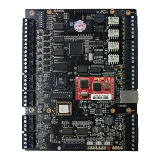
- Page 20 7.3 TCP/IP Communication Port Connection (Optional) 7.3.1 How to Connect TCP/IP Module to iTDC/iTDC-SR 1) As below figure, insert TCP/IP module to iTDC/iTDC-SR in right direction. Direction of arrows must be matched between iTDC/iTDC-SR ( JP1) and TCP/IP (JP1) module.
- Page 21 Quick Installation Guide 7.4 TCP/IP Converter (External Version) When using the TCP/IP converter for communication, select either RS232 or RS422. ILAN422 Figure: TCP/IP Converter between Host PC and iTDC/iTDC-SR INTERFACE iTDC/iTDC-SR ILAN422 TX (CON2) RX (RS232 DSUB9) RS232 RX (CON2)
- Page 22 Quick Installation Guide 7.5 Bypass Communication Wiring iTDC/iTDC-SR will be able to communicate with Host PC when internal ECP/IP module is equipped. The iTDC/iTDC-SR communicates RS422 with another iTDC/iTDC-SR. First, you have to connect iTDC/iTDC-SR RS422 port to RS422 port of iTDC/iTDC-SR (No.1 , TCP/IP communication) as below.
-
Page 23: Product Manual Download Information
For registered users of our homepage 1. Visit IDTECK’s homepage (www.idteck.com). 2. Click the Sign in button at the top of the homepage and log in using your registered ID and P/W. - Page 24 The specifications contained in this manual are subject to change without notice at any time. 5F, Ace Techno Tower B/D, 468, Gangseo-Ro, Gangseo-Gu, Seoul, 07573, Korea Tel : +82-2-2659-0055 Fax : +82-2-2659-0086 E-mail : webmaster@idteck.com FFQG0191 December. 2016 Copyright © 2016 IDTECK Co., Ltd.