IDTECK iTDC User Manual
2~4 door access control system
Hide thumbs
Also See for iTDC:
- Troubleshooting manual (94 pages) ,
- Quick installation manual (24 pages)
Table of Contents
Advertisement
Quick Links
Advertisement
Table of Contents

Related Manuals for IDTECK iTDC


Summary of Contents for IDTECK iTDC
- Page 1 USER MANUAL iTDC 2 ~ 4 DOOR ACCESS CONTROL SYSTEM...
-
Page 2: Table Of Contents
2 IDENTIFYING SUPPLLIED PARTS ......... . 2.1 STANDARD PARTS IN PACKAGE ..........2.2 OPTIONAL ACCESSORIES ..2.3 SUPPLIED PARTS FOR ITDC/ITDC-SR PACKAGE-1 OR PACKAGE-2 (2 DOORS) ..2.4 SUPPLIED PARTS FOR ITDC/ITDC-SR PACKAGE-3 OR PACKAGE-4 (3~4 DOORS) ............3 DIMENSION ............ - Page 3 3 BOARD ID (COMMUNICATION ID) SETTING ..........4 EARTH GND CONNECTION . . . 4.1 CONNECTION OF EARTH GND WHEN INSTALLING ITDC/ITDC-SR TO NEMA CASE 4.2 CONNECTION OF EARTH GND WHEN ITDC/ITDC-SR IS NOT INSTALLED ON NEMA ..............CASE............5 POWER WIRING ........... .
- Page 4 ..... 8 LED OPERATION STATUS CHECK AFTER INSTALLATION ........1 LED INDICATORS OF THE iTDC/ iTDC-SR ......2 LED INDICATORS OF THE EIO88 EXPANSION I/O BOARD ......... . .
- Page 5 ............1 SETTING MENU F1 ..........1.1 READER MODE SETTING ......... 1.2 ANTI PASS-BACK MODE SETTING ..........1.3 KEYPAD INPUT SETTING ..........1.4 DURESS MODE SETTING ........1.5 READER MODE TIME SCHEDULE SETTING ......... . . 1.6 READER OPEN CHECK SETTING ..........
- Page 6 1.4 The relation between input and output (4Door set-up: iTDC board default) ... . . 121 1.5 The relation between input and output (4Door set-up: EIO88 default) 1.6 Default values on the outputs regarding access attempts (2Door set-up: iTDC board .............. 123 default) 1.7 Default values on the outputs regarding access attempts (3Door set-up: iTDC board...
- Page 7 ........ 130 In the case of RS422 communication ...... 130 1.2 Please check if the communication address is good.... 130 Check communication address setting of software and the device...... 131 1.3 Please check if the communication port setting is good.
-
Page 8: Safety Information
Safety Information CAUTION: TO REDUCE THE RISK OF ELECTRIC SHOCK, DO NOT REMOVE COVER (OR BACK) NO USER SERVICEABLE PARTS INSIDE. REFER SERVICING TO QUALIFIED SERVICE PERSONNEL. This symbol indicates that dangerous voltage consisting a risk of electric shock is present within this unit. -
Page 9: Important Safety Instructions
9. If this product fails to operate normally, contact the nearest service center. Never disassemble or modify this product in any way. (IDTECK is not liable for problems caused by unauthorized modifications or attempted repair.) 10. - Page 10 1. Read these instructions. 2. Keep these instructions. 3. Heed all warnings. 4. Follow all instructions. 5. Do not use this apparatus near water. 6. Clean only with dry cloth. 7. Do not block any ventilation openings. Install in accordance with the manufacturer’s instructions.
-
Page 11: Notice To Prevent Trouble And Malfunction
NOTICE FOR NEMA CASE Size of the Nema Case which IDTECK sells is 350mm X 399mm X 100mm (Width X Depth X Height), and it has thickness of 1.4mm. If you use another Nema Case, the Nema Case has to be made by conductive metal and it should be bigger than IDTECK’s Nema case... -
Page 12: Notice For Installation Of Door Lock Or Automatic Door (24V)
When you supply power to each product, you must connect power GND to earth GND. SMPS (Switching Mode Power Supply) is recommended for power supply and IDTECK’s ID40WA is recommended. If device and external reader do not use same power, to match the electric potential, connect each GND to earth GND. - Page 13 STP (Shielded Twisted Pair) is recommended when you connect RS485 or RS422 communication. Connect shield wire of STP to power GND. But connect one end only. If you connect both ends of shield wire to GND, communication error might be occurred by current which is generated by mutual potential difference.
-
Page 14: Features
Features for iTDC/ iTDC-SR Intelligent multi door access control system The iTDC/ iTDC-SR is an intelligent 2~4 Door Access Controller designed to meet the market requirements for a simple and cost-effective access controller. Card registration can be set from 1,000 to 50,000 and, the cards can be registered, deleted and changed. - Page 15 Arm/Disarm Function for Alarm Panel After setup of arm/disarm code, the user enters arm code and present special card ID to the reader. The iTDC is set to arm condition and also generate output(s) for burglar alarm system. All readers in arm condition do not read any cards.
- Page 16 - Firmware Version 7.1.0 and lower iTDC/iTDC-SR: Input the time schedule code to use in terms of each of input port. Input signal generates in out of appointed time range.
- Page 17 Card registration, In/Output operating type, In/Output setting and time schedule etc can be set by the software. Also monitoring for access status of cardholder and alarm status are available in real time. IDTECK offers the applicable software STARWATCH iTDC PRO I/II and STARWATCH STANDARD.
-
Page 18: Identifying Suppllied Parts
IDENTIFYING SUPPLLIED PARTS Please unpack and check the contents of the box. (Optional accessories, if purchased, may be included in the package.) STANDARD PARTS IN PACKAGE OPTIONAL ACCESSORIES FEATURES p.11... -
Page 19: Supplied Parts For Itdc/Itdc-Sr Package-1 Or Package-2 (2 Doors)
SUPPLIED PARTS FOR ITDC/ITDC-SR PACKAGE-1 OR PACKAGE-2 (2 DOORS) Supplied parts in iTDC/iTDC-SR package-1 and package-2 are basically same but TCP/IP Module (IM100) is contained in the package-2. SUPPLIED PARTS FOR ITDC/ITDC-SR PACKAGE-3 OR PACKAGE-4 (3~4 DOORS) Supplied parts in iTDC/iTDC-SR package-3 and package-4 are basically same but TCP/IP Module (IM100) is contained in the package-4. -
Page 20: Dimension
DIMENSION Unit: inch (mm) FEATURES p.13... -
Page 21: Specification
SPECIFICATION Model iTDC iTDC-SR 8bit Microprocessor 64K Byte ROM Memory Program Memory 512K Byte Flash Memory Data Memory Users and Event Buffers Defined Available Users 1,000 ~ 20,000 / 30,000 / 40,000 / 50,000 Users 29,500~20,000 / 15,000 / 10,000 / 5,000 Events Event Buffer DC 12V, Max.500mA... - Page 22 IIM100 Internal TCP/IP Module FEATURES p.15...
-
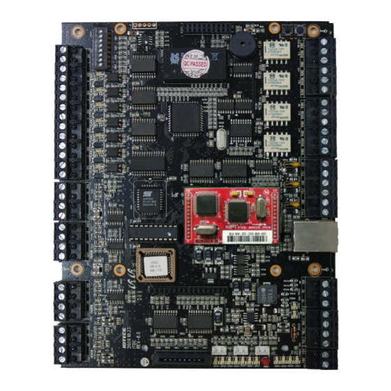
Page 23: Product Overview
PRODUCT OVERVIEW ITDC / ITDC-SR MAINBOARD 2 Door are available to control by an iTDC/iTDC-SR main board. Check the parts of iTDC/iTDC-SR main board. p.16... -
Page 24: Itdc/Itdc-Sr Board Arrangement Table
The RS422/ RS232 converter is necessary for connecting RS422 port to PC. Power Port This is main power port. iTDC is working at DC12V and max 500mA current. (It is applied only when door lock devices, alarms, sensors and reader is not connected.) PRODUCT OVERVIEW p.17... - Page 25 These ports are to connect 4 readers to the iTDC. Reader #4 Port Input #1 ~ There are input ports to connect 7 input devices to the iTDC. Input #7 Port LED #15 ~ #21 These 7 LEDs indicate the input status. NO type input: Each LED is on when the corresponding input is activated.
-
Page 26: Optional Accessories
OPTIONAL ACCESSORIES EXPANSION I/O BOARD The EIO88 board features: 8 Inputs ports ● 8 FORM-C Relay Output ports ● 4 Inputs can be configured to Door 3 ~ 4 as of exit buttons and door contact sensors. ● 4 Output Relays can be configured to Door 3 ~ 4 as of door locks and alarm devices. -
Page 27: Eio88 Board Arrangement Table
TCP/IP communication to the host PC. KEYPAD The user can connect the optional Keypad to the iTDC main control board and the user can use the keypad with the LCD display module when the user sets up all functions to the iTDC manually. p.20... -
Page 28: Lcd Display Module
LCD DISPLAY MODULE The user can connect the optional LCD display module to the iTDC main control board and the user can use the LCD display module with the optional keypad when the user sets up all functions to the iTDC manually. -
Page 29: Preparation Of Installation
PREPARATION OF INSTALLATION CONFIGURATION DEPENDING ON TYPE OF COMMUNICATION CONFIGURATION FOR RS232 COMMUNICATION Configuration for RS232 communication is same as figure below. Please refer to more information of applicable cable in “RECOMMENDED CABLE TYPE AND PERMISSIBLE LENGTH CABLE”. p.22... -
Page 30: Configuration For Rs422 Communication
There are two kinds of connection type of TCP/IP communication. TCP/IP CONFIGURATION OF DIRECT COMMUNICATION All connecting iTDC/iTDC-SRs equip internal TCP/IP module (IIM100) then each of them are connected to HUB to link Host PC and LAN. Please refer to more information of applicable cable in “RECOMMENDED CABLE TYPE AND PERMISSIBLE LENGTH OF... -
Page 31: Configuration Of Installation For Tcp/Ip Bypass Communication
CONFIGURATION OF INSTALLATION FOR TCP/IP BYPASS COMMUNICATION. Internal TCP/IP module (IIM100) is equipped on a iTDC/iTDC-SR then it communicates LAN with Host PC. The iTDC/iTDC-SR communicates RS422 with another iTDC/iTDC-SR. Please refer to more information of applicable cable in “RECOMMENDED CABLE TYPE AND... -
Page 32: Recommended Cable Type And Permissible Length Of Cable
Reference Description Cable Specification Maximum Distance iTDC/iTDC-SR Power (DC12V) Belden #9409, 18 AWG DC Power ↔ iTDC 2 conductor, unshielded Reader (Power and Data) Belden #9512, 22 AWG 150m Extra Reader ↔ iTDC/iTDC-SR 4 conductor, shielded Belden #9514, 22 AWG... -
Page 33: How To Equip Optional Specification
Cable Specification Maximum Distance 8 conductor, shielded Door Lock, Alarm Device Belden #9409, 18AWG 300m Lock (Alarm) ↔ iTDC/iTDC-SR 2 conductor, unshielded RS232 Cable Belden #9829, 24 AWG Converter ↔ Host P.C. 2-twisted pair, shielded RS485 Cable Belden #9829, 24 AWG 1,200m iTDC/iTDC-SR ↔... -
Page 34: Equipment Of Expansion In/Output Board (Eio88)
TCP/IP module and iTDC/iTDC-SR have to be matched. EQUIPMENT OF EXPANSION IN/OUTPUT BOARD (EIO88) Fix hexagon supporters on iTDC/iTDC-SR main board by using four screws as figure below then, put EIO88 on them. After matching between the board and the EIO88 then fix the EIO88 by the other four screws from top. -
Page 35: Equipment Of Keypad
EQUIPMENT OF KEYPAD To use optional keypad, connect the keypad to keypad port as figure below. p.28 PREPARATION OF INSTALLATION... -
Page 36: Equipment Of Lcd Module
EQUIPMENT OF LCD MODULE To use optional LCD module, connect the keypad to keypad port as figure below. PREPARATION OF INSTALLATION p.29... -
Page 37: Product Installation
PRODUCT INSTALLATION DESCRIPTION OF PORTS FOR WIRING ITDC/ITDC-SR MAIN BOARD PORT p.30... -
Page 38: Expansion I/O Board (Eio88) Port
Name Power Port RS422 Communication Port RS232 Communication Port TTL Output (#1 ~ #3) Port Relay Output(#1 ~ #4) Port Board ID Setting Switch Input(#1 ~ #7) Port Reader(#1 ~ #4) Port EXPANSION I/O BOARD (EIO88) PORT Name Input (#1 ~ #4) Port... -
Page 39: Procedure Of Product Installation
There is an 8 channel DIP switch on the right upper side of the iTDC board for board ID setting. Each channel of DIP switch has assigned address values and the board ID is the sum value of each switch set to “ON”... -
Page 40: Earth Gnd Connection
If more than one iTDC boards are installing, you must set different Board ID for each iTDC board. If it is duplicated, the communication error may occur. EARTH GND CONNECTION CONNECTION OF EARTH GND WHEN INSTALLING ITDC/ITDC-SR TO NEMA CASE If iTDC/iTDC-SR has purchased by package, ground Earth GND as figure below. - Page 41 No. / Name How to connect Earth GND 1. Nema case The Nema case IDTECK offers is metal Nema Case but if you are used other nema case, metal Nema Case must be used. 2. Supporter All supporters (Supporter to connect iTDC/iTDC-SR main board to EIO88,...
-
Page 42: Case
CONNECTION OF EARTH GND WHEN ITDC/ITDC-SR IS NOT INSTALLED ON NEMA CASE. If you don’t install iTDC/iTDC-SR in Nema case, GND wire of power port of each device must be grounded to Earth GND. GND connection makes zero for potential difference and prevents malfunctions from thunderbolt and surge. -
Page 43: Power Wiring
Must check if power is off when you wire. If power is on when you wire, you get an electric shock. POWER WIRING Connect (+) wire (Red) of DC 12V power to +12V terminal of iTDC/iTDC-SR Mainboard ● power port. -
Page 44: Input Device Wiring
INPUT DEVICE WIRING You can connect door contact and exit button, etc to input ports (INPUT#1~INTPUT#7) of iTDC/iTDC-SR. Depending on number of door control, wire input device as following table below. I/O board (EIO88) is required to control 3, 4 doors. -
Page 45: 3-Door Control
3-DOOR CONTROL Firstly equip I/O board(EIO88) to iTDC/iTDC-SR then wire. Door 1 is controlled by main board of iTDC/iTDC-SR and door 2 and 3 are controlled by I/O board (EIO88). Connect to Input#1 of iTDC/iTDC-SR main board Door 1... -
Page 46: Output Device Wiring
Connect to Input#4 of EIO88 Door Contact 1. If reader or input device is installed on metal frame, you must ground between the metal frame and Earth GND otherwise static electricity of metal frame flows to device then it causes malfunctions and shortens life of the product. -
Page 47: 2-Door Control
Door 1 Door Lock iTDC/iTDC-SR main board. Connect (+) wire of door lock to R1NC port of iTDC/iTDC-SR main board. Connect (-) of door lock to GND (-) wire of DC12V power device. Connect anti-inverse voltage diode between (+) wire and (-) wire of door loack. -
Page 48: Wiring For Door Lock, Alarm In Power Fail Secure Mode
Connect +12V wire of DC12V power device to R1COM port of Door 1 Door Lock iTDC/iTDC-SR main board. Connect (+) wire of door lock to R1NO port of iTDC/iTDC-SR main board. Connect (-) wire of door lock to GND (-) wire of DC12V power PRODUCT INSTALLATION... - Page 49 Connect +12V wire of DC12V power device to R3COM port of Door 2 Door Lock iTDC/iTDC-SR main board. Connect (+) wire of door lock to R3NO port of iTDC/iTDC-SR main board. Connect (-) wire of door lock to GND (-) wire of DC12V power device.
-
Page 50: 3-Door Control
3-Door control Firstly equip I/O board (EIO88) to iTDC/iTDC-SR then wire. Door 1 is controlled by main board of iTDC/iTDC-SR and door 2, 3 are controlled by I/O board (EIO88). Connect to RL1 port of iTDC/iTDC-SR main board. Door 1... -
Page 51: Wiring For Using 24V Door Lock Or Automatic Door
If you don’t use separate power device or external relay, relay can be destroyed and it may causes malfunctions. READER WIRING RF reader can be connected to reader port (READER#1~ READER#4) of iTDC/iTDC-SR. Depending on number of doors, wiring can be different so follow the table below. 2-Door Control For 2-Door Control, a door is connected to external reader for entrance and the other door is connected to internal reader for exit. - Page 52 Connect D0 wire (Green) to D0 of READER#1 port of iTDC/iTDC-SR main board. Connect D1 wire (White) to D1 of READER#1 port of iTDC/iTDC-SR main board. Connect +12V wire (Red) to +12V of READER#2 port of Internal Reader iTDC/iTDC-SR main board.
-
Page 53: 3-Door Control (If External Reader And Internal Reader Are Connected To Door 1.)
3-Door Control (If external reader and internal reader are connected to door Firstly equip I/O board (EIO88) to iTDC/iTDC-SR then wire. 3 external readers and an internal reader are controlled by main board of iTDC/iTDC-SR and 2 exit buttons are controlled by I/O board (EIO88). -
Page 54: 3-Door Control (If External Reader And Exit Button Are Connected To Door1)
Connect INPUT#3 port of EIO88. RF reader can use external power but GND of external power and GND of iTDC/iTDC-SR has to be grounded as common ground in this case, otherwise communication error and system troubles are caused by noise from outside then device’s life is shortened. -
Page 55: Wiring To Control Led/Buzzer Of Reader
WIRING TO CONTROL LED/BUZZER OF READER LED and Buzzer can be controlled by relay output of iTDC/iTDC-SR. This function is used to check for door open status by LED of reader or Buzzer sound. Check the door lock type (whether to Power Fail Safe or Power Fail Secure) then follow the description below to wire. - Page 56 2~4 doors and depending on number of door control, In/Output port is changed. If 2 doors are controlled, iTDC/iTDC-SR main board is operated alone and to use 3~4 doors, you have to use I/O board (EIO88). In the case of using 3, 4 doors, setting for number of door control is allowed by Application Software.
- Page 57 Normal Output Alarm control (Door Lock) Output(Alarm) Door Entrance READER iTDC RELAY#1 iTDC RELAY#2 (Equipment of EIO88) Exit READER iTDC INPUT#1 iTDC RELAY#1 iTDC RELAY#2 Door Entrance READER EIO88 RELAY#1 EIO88 RELAY#2 Exit EIO88 EIO88 RELAY#1 EIO88 INPUT#1 RELAY#2 Door...
- Page 58 INPUT#1 Door Entran READE EIO88 RELAY#3 EIO88 RELAY#4 Exit EIO88 EIO88 RELAY#3 EIO88 RELAY#4 INPUT#3 Default value for setting number of door is 2. You must change the setting value of number of door if EIO88 is equipped to use more than 3 doors. In/Output of EIO88 is not operated in status of 2 doors as default value.
-
Page 59: Communication Wiring
COMMUNICATION WIRING RS232 COMMUNICATION PORT CONNECTION A 9-pin connector (Serial communication connector, female) is required to connect the iTDC to a host computer via RS232 communication. Please follow the instructions below; Connect RS232-TX port of iTDC to the pin #2 of the 9-pin connector. -
Page 60: Rs422 Communication Port
Plug in the RS232 9-pin connector of the converter to the COM Port of the PC. ● Install and run the iTDC Application Software.(STARWATCH iTDC PRO I, II or STANDARD) ● If you don’t have serial port on the PC, purchase separate serial multi port card then equip it on main board of PC. -
Page 61: Connection (Multiple Itdc Connections)
2. Connection of RS422/RS232 converter to iTDC/iTDC-SR I. Firstly, connect RS422/RS232 converter to first iTDC/iTDC-SR as cross type. i. Connect RS422-RX(+) of the one iTDC to TX(+) port of the converter. ii. Connect RS422-RX(-) of the one iTDC to TX(-) port of the converter. - Page 62 1. Recommended communication cable STP (Shielded Twisted Pair) cable is recommended to wire RS422 communication. 2. GND Wiring Connect one end of Shield wire to power GND of device as figure above. If both ends of Shield wire are connected to GND, current flows by potential difference then it makes communication error.
-
Page 63: Connection Using The Tcp/Ip Module (Internal Version)
(INTERNAL VERSION) Using one IP (TCP/IP module), multiple iTDCs can communicate with a host computer. Single unit of main iTDC uses a TCP/IP internal module for LAN communications with the host computer. The main iTDC communicates with other iTDC controllers using the RS422 connection. - Page 64 1. Recommended communication cable STP (Shielded Twisted Pair) cable is recommended to wire RS422 communication. 2. GND Wiring COMMUNICATION WIRING p.57...
-
Page 65: External Tcp/Ip Converter (Ilan422)
Set the communication setting switch to RS232. The switch is located at upper left of ● ILAN422. Connect TX of iTDC/iTDC-SR RS232 port to RX (pin 2) of ILAN422. ● Connect RX of iTDC/iTDC-SR RS232 port to TX (pin 3) of ILAN422. - Page 66 Connect RX+ of iTDC/iTDC-SR RS422 port to TX+ of ILAN422. ● Connect RX- of iTDC/iTDC-SR RS422 port to TX- of ILAN422. ● COMMUNICATION WIRING p.59...
-
Page 67: Led Operation Status Check After Installation
LED INDICATORS OF THE iTDC/ iTDC-SR The LEDs for indicating the status of the iTDC/iTDC-SR are located as shown on the Figure: iTDC/iTDC-SR Board Layout. Each LED will be turned on and off as the following status of the iTDC/iTDC-SR LED #1 ~ LED #2 These two LEDs indicate the communication status. -
Page 68: Led Indicators Of The Eio88 Expansion I/Oboard
LED INDICATORS OF THE EIO88 EXPANSION I/O BOARD The LEDs for indicating the status of the EIO88 Expansion I/O Board are located as shown in the Figure: EIO88 Expansion I/O Board Layout (16p). Each LED will be turned on and off as the following status of the EIO88 Expansion I/O Board. -
Page 69: Basic Setting
BASIC SETTING You have to connect optional LCD display and Keypad to iTDC for the following manual settings. But, Initialization is available without LCD and Keypad as description below. INITIALIZATION Press down the two initialization switches simultaneously and then keep pressing for 2 seconds. -
Page 70: How To Use Keypad
If you purchased optional keypad, check the description below to use it. HOW TO ENTER THE SETUP MENU To set-up or to change the iTDC settings, you have to enter the SETUP MENU first. Follow instructions below. 1. Press <0> key 8 times for Master ID (Default setting “00000000”) and <ENT> key. -
Page 71: Door Setting
Input sources and Output Relays upon to the number of doors to be controlled by iTDC. Press <F2> key once then press <6> key or <4> key until the LCD shows [8.DOOR SETTING] in the [SETUP MENU F2] then press <ENT> key to change the DOOR SETTING. -
Page 72: Date And Time Setting
1 for Sunday, 2 for Monday, 3 for Tuesday, 4 for Wednesday, 5 for Thursday, 6 for Friday and 7 for Saturday. The Master ID for iTDC-SR is 10 digits number (Default setting “0000000000”). -
Page 73: Reference For Lcd Display
Reference for LCD Display This error message will be displayed when you press <ENT> key in the [MAX USER SET] menu and it means that some events are still existing in the EVENT Buffer and you may lost the data when you change the MAX USER SET. -
Page 74: Id Registration
ID REGISTRATION You can register the User ID into the iTDC. Select [SETUP MENU F3] -> [ID REG.] then follow the steps below: The Master ID for iTDC-SR is 10 digits number (Default setting “0000000000”). Reference for LCD Display... - Page 75 The group #1 ID (1) and group #2 ID (2) perform same operation with general user. The special ID (3) is used to set “ARM/DISARM ”. But the special ID (3) is used as general user (0) if the special ID (3) is authorized to the iTDC /iTDC-SR with not entering “ARM/DISARM CODE”.
- Page 76 Reader #1 is accessible and if you put ‘0’ for RA then the cardholder cannot access through the Reader #1 and iTDC generates an error message “Access Door Error” and displays on the LCD. To get access through all 4 Readers, you have to input ‘1’...
-
Page 77: Setting Changes
SETTING CHANGES To set-up or to change the iTDC settings, you have to enter the SETUP MENU first. To do so, press 8 times <0> key for Master ID (Default setting “00000000”) and <ENT> key from the p.70... -
Page 78: Setting Menu F1
SUB MENU by pressing <4> and <6> key in the main SETUP MENU. If you don’t press any key for 20 seconds or if you press <ESC> key then iTDC will exit the SETUP MENU then return to normal operation. The Master ID for iTDC-SR is 10 times <0>... - Page 79 SETTING CHANGES...
-
Page 80: Reader Mode Setting
READER MODE SETTING It shows READER1 MODE is set to RF ONLY operating mode. If you want to change the mode to RF+PASSWORD operating mode, press <ENT> key. SETTING CHANGES p.73... -
Page 81: Anti Pass-Back Mode Setting
Now you can change the mode by pressing <4> or <6> key to toggle the mode. If you want to set-up the mode displayed then press <ENT> key to accept this mode. RF ONLY The door is accessible with the proximity card alone. -
Page 82: Keypad Input Setting
Door1. When you select USE (ZONE) then Door2 entry is not possible after you got in through Door1. (APB error) If you select ALL CLEAR then iTDC will clear all APB flags and all users are allowed to enter or exit once regardless of access status. -
Page 83: Duress Mode Setting
Once it is set as “DISABLE”, no entrance or exit is possible through keypad of the reader. DURESS MODE SETTING You can select whether the DURESS mode is used or not used for READER1. To use this function, you need Keypad Reader. Default setting is NOT USE. If you want to set-up Duress mode then press <ENT>... -
Page 84: Reader Mode Time Schedule Setting
RF+PASSWORD mode. To apply this function, you have to set-up Time Schedules (T/S) and Holiday Schedules (H/S) from the iTDC Application Software and download T/S with H/S index to the iTDC. Please refer to iTDC Software Manual for detail. -
Page 85: Reader Open Check Setting
The reader outputs “00000000” through reader’s data wire once within 60sec. At this time, if “00000000” is transmitted by the reader in the iTDC, the unit judges that reader is normally connected. Therefore you can know connection status of reader without additional wiring. -
Page 86: Setting Menu F2
To activate READER OPEN CHECK Function, a reader that is generating SUPERVISOR signal is required. SETTING MENU F2 SETTING CHANGES p.79... - Page 87 SETTING CHANGES...
-
Page 88: Time Setting
TIME SETTING Press <ENT> key and enter 15 digit Date/Time codes then <ENT> key to finish setting. YYYY: Year, MM: Month, DD: Date hh: Hours (24 hours system), mm: Minutes, ss: Seconds W: Sun=1, Mon=2, Tue=3, Wed=4, Thu=5, Fri=6, Sat=7 Example: 200902101330152 =>... -
Page 89: Comm Id(Communication Id, Board Id) Display
4800, 9600, 19200 and 38400bps of baud rate and default setting is 9600bps. Wrong baud rate setting will cause communication errors and you have to set same baud rate to iTDC and host PC. If you have communication problem, please check followings;... -
Page 90: Master Id Change
You can select whether you protect event memory or not. When you select USE and in case of event memory full then iTDC generates an error message and keeps all events stored in the memory. When you select NOT USE then iTDC will not generate an error and new event SETTING CHANGES p.83... -
Page 91: Door Open Alarm Setting
If you use iTDC for standalone (just for door access) then select NOT USE. Choosing “NOT USE” will allow resetting ID/EVENT COUNT to delete saved EVENT Memory. DOOR OPEN ALARM SETTING When the door is still opened after the door unlock time, you may set this alarm function. To use this function, you have to install Door Contact Sensor on the door and set-up the output of Door Contact Sensor from the iTDC Application Software. -
Page 92: Holiday Setting
2 DOOR Reader#1-Door1 Entry, Reader#2-Door1 Exit Reader#3-Door2 Entry, Reader#4-Door2 Exit 3 DOOR Reader #1-Door1 Entry, Reader #2-Door1 Exit Reader#3-Door2 Entry, Reader#4-Door3 Entry 4 DOOR Reader#1, #2, #3, #4-Door1, 2,3,4 Entry Door setting must be set-up first before other set-up. Please refer to section 8.3 DOOR SETTING. -
Page 93: Time Schedule Setting
You can register up to 100 specified holidays per year for each schedule setting. There can be 10 other registration sets created, meaning holidays can be set for up to 10 years. Press <ENT> to register the days. With the <2> key and <8> key, select the Date Registration Set Number (1~10), and with the <4>... - Page 94 A Menu to Register or Change Time Schedule. To do that, press <ENT> on this Screen. You can input time in 24 time system. (i.e. PM5 -> 17) . You can divide and set a day into 5 sections in this Time Schedule Menu Press <2>...
-
Page 95: Defining Input Time In Compliance With Inputs
Valid values for time scheduling 1) Time schedule number: 01 ~ 15 (Needed when IDs are registered) 2) A day of the week: MON, TUE, WED, THU, FRI, SAT, SUN, HOL 3) Index: 1 ~ 5 (1 Day is divided and set to 5 sections) 2.11... - Page 96 Press <ENT> key and you will see a cursor blinking at the first digit from the left of the seven couples of digits (Output of iTDC). Enter the 14 digit (seven couples) key. Press <ENT> key and you will see a cursor blinking at the first digit from the left of the eight couples of digits (Output of EIO88).
-
Page 97: Defining Output Time In Compliance With Reader
2.12 DEFINING OUTPUT TIME IN COMPLIANCE WITH READER You can program or deactivate each output to be generated and choose how long (in seconds) they will last. There are default values as seen in the APENDIX (A. THE RELATION BETWEEN INPUT AND OUTPUT (DEFAULT) Select input sources by changing Index numbers with the keys <4>... -
Page 98: System Initialize
2.13 SYSTEM INITIALIZE This operation will initialize the iTDC. Press <ENT> key, if an initialization is needed. Prior to system initialization, make sure to check whether or not the data stored in the device is not needed, since it will be deleted after the initialization. -
Page 99: Event Clear
Press <1> key to initialize or <0> key to cancel the operation. This message appears while the system is being initialized. After the initialization, iTDC will return to the set-up menu. 2.14 EVENT CLEAR When the event memory is full or when you want to change ID COUNT, you can clear the event memory in this menu. -
Page 100: Time Schedule Clear
Prior to clearing card IDs, make sure to check whether or not the data stored in the device is not needed, since it will be deleted after the card ID clear. 2.16 TIME SCHEDULE CLEAR When you want to delete all Time Schedule (01~15), you can clear all T/S from the memory. -
Page 101: Setting Menu F3
SETTING MENU F3 p.94 SETTING CHANGES... -
Page 102: Id Registration
ID REGISTRATION Press <ENT> key to register new User ID. Enter 8 digit Card ID in the ID [________] field and press <ENT> key. For 8 digits user ID, First 3 digits should be between 000 and 255, and last 5 digits should be between 00000 and 65535 Enter 4 digits Password in the PW [____] field and press <ENT>... -
Page 103: Id Deletion
When you want to apply T/S 01 for Reader#1 (TA), T/S 02 for Reader#2(TB), T/S 02 for Reader#3(TC) and T/S 00 for Reader#4(TD) and you want to use Reader#1, #2, #3 only. Press <0><1><0><2><0><2><0><0><ENT> key for T/S ID number of iTDC-SR is a 10 digit number between 0000000000 and 4294967295. ID DELETION p.96... - Page 104 User ID is not found then only display “ID Unregistered”. You may repeat ID DELETE many times and press <ESC> key to exit the menu. ID number of iTDC-SR is a 10 digit number between 0000000000 and 4294967295. SETTING CHANGES...
-
Page 105: Id List
ID LIST If you want to see the list of registered User ID, press the <ENT> key in this menu. IDs are sorted by order or registration. 8 digit User ID, 4 digit password and 1 digit code (ID type) are displayed on the LCD. -
Page 106: Registered Id Count
LCD. “ID LIST BOTTOM” message will be displayed first when the last registered User ID is displayed on the LCD. ID number of iTDC-SR is 10-digit number. REGISTERED ID COUNT This menu displays the total number of registered User ID. -
Page 107: Max User Setting
MAX USER SETTING Press <ENT> key to change maximum User ID. MAX USER SETTING must be set-up first before other set-up. Enter number from 1000 to 20000 in multiple of 1000 for the maximum User ID. Every time 1000 user IDs increase, 500 event buffers decrease. The default ID COUNT is 5,000 Users and the default EVENT Buffer size is 27,500. -
Page 108: Stored Event Count
LCD will display “INVALID NUMBER” error message when you enter the ID Count which is not multiple of 1,000 or the ID Count is not in between 1,000 and 20,000. LCD will display “EVENT MEMORY NOT EMPTY!!!” error message when you want to change ID Count and there are some events still existing in the Event Buffer. -
Page 109: Arm/Disarm Code
You can choose data format between 4/8Bit burst and 26Bit weigand to transmit reader button input signal. The Default is 4/8Bit burst. If you choose 26Bit weigand, HID readers that use 26Bit wiegand can be used, but on the other hand, IDTECK’s readers cannot be used. ARM/DISARM CODE p.102... - Page 110 If you want to set “ARM/DISARM CODE”, press the <ENT> key in this menu. Press 2 digit of ARM CODE. “00” is default which means not to use this function. Make sure that number must be different from “Duress P/W” or “Disarm Code”.
-
Page 111: Arm/Disarm Port
Set whether to use input port that can set ARM / DISARM function. Input port is fixed by input port #7 of iTDC (default: “0”).If you wish to use ARM / DISARM function with port of input device, press “7” key. According to input signal, the unit operates on toggle mode. -
Page 112: Arm Code Process Details
ARM CODE PROCESS DETAILS ARM CODE has to be different from DISARM CODE. SETTING CHANGES p.105... -
Page 113: Disarm Code Process Details
DISARM CODE PROCESS DETAILS ARM CODE has to be different with DISARM CODE. p.106 SETTING CHANGES... -
Page 114: Arm / Disarm Input Process Details
ARM / DISARM INPUT PROCESS DETAILS ARM/DISARM Input Port is fixed as setting value of Input # 7. 3.10 2 MEN OPERATION MODE SETTING Set whether to use “TWO MEN MODE” or not. Default value is set to “NOT USE”. -
Page 115: Input Time Schedule Mode Setting
When you register ID, you should register code to group#1 ID (1) and group#2 ID (2).When the user of these two groups tries authenticating on the iTDC/iTDC-SR that is set “NOT USE TWO MEN MODE”, they are given same authorization with general user (0). -
Page 116: Setup Menu F4
When time schedule applied on the input, it only processes the input that occurs out of the time schedule section. If the application software, STARWATCH iTDC PRO I/II is used for time schedule setting, the ‘OLD MODE’ is automatically applied in the operation. If the application software, STARWATCH STANDARD, is used for time schedule setting, the ‘NEW... - Page 117 SETTING CHANGES...
-
Page 118: Version Check
VERSION CHECK The version of the controller’s firmware is displayed on the LCD. Pressing <ENT> here shows you the last update date Press <4> or <6> key to look for other menus of set-up menu F4. RAM TEST To test the RAM memory, press <ENT> key. -
Page 119: Outputs Test
To test the outputs, press <ENT> key. By pressing key 1 or 2, select between iTDC and EIO88 for output test. Select output port test by key 1 then output ports of iTDC 1 ~8 and status are displayed on LCD. -
Page 120: Keypad Test
To test the LCD, press <ENT> key. LCD will display all characters on each part of the screen. If not, it means that there is a problem with LCD. Please contact local tech support. When the test is done, LCD will show “Last Update Press any key…” then press any key to return to the set-up menu. -
Page 121: Reader Test
When the reader successfully read the card, LCD will display reader number and 8-digit card number on the LCD. It returns to standby status automatically in about 1 sec. ID number of iTDC-SR is 10 digit number. INPUT AND DIP SWITCH TEST To test the reader, press <ENT>... -
Page 122: Communication Test
(or 2,3) of the JP3, 4. This test is a loop test and iTDC sends a character to TX port and check whether the RX port receive the character or not. If you have an error, please contact our service facility. - Page 123 After the test is done, LCD will display “COMM test pass!!” You can see “Tx data” and “Rx data” before this screen. Press any key to return to the set-up menu. p.116 SETTING CHANGES...
-
Page 124: Appendix
APPENDIX THE DEFAULT VALURES DEPENDING ON INPUT(INPUT PORT / READER INPUT) The relation between input and output (2Door set-up: iTDC board default) Index No Relay#1 Relay#2 Relay#3 Relay#4 TTL#1 TTL#2 TTL#3 [1] Input #1 (Door1 Exit button) [2] Input #2 (Door1 Contact... -
Page 125: The Relation Between Input And Output (3Door Set-Up: Itdc Board Default)
INPUT Type: “00”= NC, “01”= NO DR TIME OUT 1~4 (Door Time Out 1~4): It is interval time between door opening and closing when door opening time is over. The relation between input and output (3Door set-up: iTDC board default) Index No Relay#1... -
Page 126: The Relation Between Input And Output (3Door Set-Up: Eio88 Extension I/O Board Default)
Index No Relay#1 Relay#2 Relay#3 Relay#4 TTL#1 TTL#2 TTL#3 [15] EIO88 Input #8 [16] DURESS MODE 1 [17] DURESS MODE 2 [18] DURESS MODE 3 [19] DURESS MODE 4 [20] OUTPUT Time Schedule [21] INPUT Time Schedule [22] INPUT Type... -
Page 127: The Relation Between Input And Output (4Door Set-Up: Itdc Board Default)
INPUT Type: “00”= NC, “01”= NO DR TIME OUT 1~4 (Door Time Out 1~4): It is interval time between door opening and closing when door opening time is over. The relation between input and output (4Door set-up: iTDC board default) Index No Relay#1... -
Page 128: The Relation Between Input And Output (4Door Set-Up: Eio88 Default)
Index No Relay#1 Relay#2 Relay#3 Relay#4 TTL#1 TTL#2 TTL#3 [5] Input #5 [6] Input #6 [7] Input #7 [8] EIO88 Input #1 (Door3 Exit) [9] EIO88 Input #2 (Door3 Contact) [10] EIO88 Input #3 (Door4 Exit) [11] EIO88 Input #4 (Door4... - Page 129 Index No Relay# Relay# Relay# Relay# Relay# Relay# Relay# Relay# Button) [2] Input #2 (Door1 Contact [3] Input #3 (Door2 Exit Button) [4] Input #4 (Door3 Contact [5] Input #5 [6] Input #6 [7] Input #7 [8] EIO88 Input #1 (Door3...
-
Page 130: Default Values On The Outputs Regarding Access Attempts (2Door Set-Up: Itdc Board Default)
INPUT Type: “00”= NC, “01”= NO DR TIME OUT 1~4 (Door Time Out 1~4): It is interval time between door opening and closing when door opening time is over. Default values on the outputs regarding access attempts (2Door set-up: iTDC board default) Index No... -
Page 131: Default Values On The Outputs Regarding Access Attempts (3Door Set-Up: Itdc Board Default)
But, two functions (1 & 2) cannot be used at the same time. Default values on the outputs regarding access attempts (3Door set-up: iTDC board default) Index No Relay#1 Relay#2 Relay#3 Relay#4 TTL#1 TTL#2 TTL#3 [1] Reader#1 ID OK... -
Page 132: Default Values On The Outputs Regarding Access Attempts (3Door Set-Up: Eio88 Default)
Default values on the outputs regarding access attempts (3Door set-up: EIO88 default) Index No Relay#1 Relay#2 Relay#3 Relay#4 Relay#5 Relay#6 Relay#7 Relay#8 [1] Reader#1 ID OK [2] Reader#1 ID Error [3] Reader#1 ID T/S Error [4] Reader#1 APB Error 00... -
Page 133: Default Values On The Outputs Regarding Access Attempts (4Door Set-Up: Itdc Board Default)
But, two functions (1 & 2) cannot be used at the same time. Default values on the outputs regarding access attempts (4Door set-up: iTDC board default) Index No Relay#1 Relay#2 Relay#3 Relay#4 TTL#1 TTL#2 TTL#3 [1] Reader#1 ID OK... -
Page 134: Default Values On The Outputs Regarding Access Attempts (4Door Set-Up: Eio88 Default)
1.10 Default values on the outputs regarding access attempts (4Door set-up: EIO88 default) Index No Relay#1 Relay#2 Relay#3 Relay#4 Relay#5 Relay#6 Relay#7 Relay#8 [1] Reader#1 ID OK [2] Reader#1 ID Error [3] Reader#1 ID T/S Error [4] Reader#1 APB Error 00... - Page 135 But, two functions (1 & 2) cannot be used at the same time. p.128 APPENDIX...
-
Page 136: Troubleshooting
Troubleshooting Before requesting RMA, please check the cases below if your problem is one of them. 1 The device dose not communicate with PC. 2 When turning on the device, Date / Time is not displayed on the LCD and special characters are displayed. -
Page 137: In The Case Of Rs422 Communication
In the case of RS422 communication See [Communication] > [RS422 Communication Port Connection] of the manual and check if the wiring is good. Please check if the communication address is good. Check communication address setting of software and the device. -
Page 138: Please Check If The Communication Port Setting Is Good
1. Check if communication ID set in the device is same with communication ID set in a software. See [Setting Changes] > [SETUP MENU F2] > [COMM ID(COMMUNICATION ID, BOARD ID) DISPLAY] and check a communication address set in the device. -
Page 139: Please Check If The Device Is Grounded Well
Please check if the device is grounded well. See [Communication] >[RS-422 CONNECTION (MULTIPLE ITDC CONNECTIONS)] of the manual and check if the device is grounded well. If the problem persists, connect service center. When turning on the device, Date / Time is not displayed on the LCD and special characters are displayed. -
Page 140: This May Happen When The Device Is Not Initialized. Please Initialize The Device
This is for when using LCD and Keypad modules with the device. This may happen when the device is not initialized. Please initialize the device. See [Basic setting] > [Initialization] or [Setting changes] > [Setup menu F2] > [System Initialization] of the manual and initialize the device. -
Page 141: A Master Id May Have Changed
A MASTER ID may have changed. 1. Change the MASTER ID from software and transmit it to the device. 2. If you cannot change MASTER ID using software, see [Basic setting] > [Initialization] or [Setting changes] > [Setup menu F2] > [System Initialization] of the manual and initialize the device. -
Page 142: When The Device Have Read A Card, The Device Does Not Response Or A Different Card Number Appears
GND of the device. Please check if software settings are good. 1. In the case of using iTDC, check if controller definition of a software is set to iTDC-SR. If it is iTDC-SR, change it to iTDC. -
Page 143: Registered Card Is Not Authenticated
If the problem persists, please contact service center A registered card is not authenticated. Please check output setting of the device. See [Appendix] > [THE DEFAULT VALURES DEPENDING ON INPUT(INPUT PORT / READER INPUT)] of the manual and set output for each doors of the device. -
Page 144: Fcc Registration Information
FCC REGISTRATION INFORMATION FCC Requirements Part 15 Caution: Any changes or modifications in construction of this device which are not expressly approved by the responsible for compliance could void the user's authority to operate the equipment. NOTE: This device complies with Part 15 of the FCC rules. Operation is subject to the following two conditions;... -
Page 145: Rma Request
RMA Request To make the RMA request, the product must be initially registered on IDTECK webpage. After registering the product, send it to IDTECK RMA Center. Please follow the instructions below: 1. Please register the RMA request via IDTECK webpage. - Page 146 IDTECK Headquarter and RMA Center 5F, Ace Techno Tower B/D, 468, Gangseo-ro, Gangseo-Gu, Seoul, 07573, Korea Tel: +82 2 2659 0055 Fax: +82 2 2659 0086 E-mail: webmaster@idteck.com Website: www.idteck.com E-Training Center: http://www.idtecktraining.com The specifications contained in this manual are subject to change without notice at any time.