Vaisala VaiNet RFL100 User Manual
Wireless
Hide thumbs
Also See for VaiNet RFL100:
- Quick manual (172 pages) ,
- User manual (56 pages) ,
- Quick manual (79 pages)
Table of Contents
Advertisement
Advertisement
Chapters
Table of Contents

Related Manuals for Vaisala VaiNet RFL100


Summary of Contents for Vaisala VaiNet RFL100
- Page 1 M211861EN-D User Guide Vaisala VaiNet Wireless Data Logger RFL100...
- Page 2 This product contains software developed disclosed to a third party without prior by Vaisala or third parties. Use of the written permission of the copyright holder. software is governed by license terms and Translated documents and translated...
- Page 3 When to use info mode................32 4.2.2 Turning on info mode................32 Remote management..................33 Releasing RFL100 from viewLinc Monitoring System....... 34 4.4.1 Releasing using release button..............35 4.4.2 Releasing remotely using viewLinc............35 Vaisala Insight software.................36 4.5.1 Connecting probe to Insight software..........37...
-
Page 4: Verifying Operation Of Rfl100
RFL100 User Guide M211861EN-D Maintenance....................38 Cleaning RFL100.....................38 Changing the probe filter................38 Probe replacement..................39 5.3.1 Probe replacement and viewLinc alarms..........39 5.3.2 Replacing a probe when one probe is connected......40 5.3.3 Replacing probes when two probes are connected......42 5.3.4 Changing from one probe to two probes.......... -
Page 5: Table Of Contents
List of figures List of figures Figure Connecting RFL100 to the viewLinc Monitoring System....... 8 Figure 2 Front and display..................... 10 Figure 3 Under the silicone plug.................. 10 Figure 4 Rear and inside....................11 Figure 5 Mounting bracket....................11 Figure 6 Alarm indicators on RFL100 display............16 Figure 7 RFL100 with high alarm active on channel 1..........17... - Page 6 RFL100 User Guide M211861EN-D List of tables Table Document versions (English)................5 Table 2 Related manuals....................6 Table 3 Battery level indicator..................12 Table 4 Symbols........................ 13 Table 5 Connection states....................13 Table 6 Signal strength indicator..................15 Table 7 Alarm symbols....................16 Table 8 Specifications for a USB power supply............
-
Page 7: Table Document Versions (English)
Files and folders in USB filesystem (page 18) • Replacing a probe when one probe is connected (page 40) • Vaisala Insight software (page 36) • Adjusting measurement using Insight software (page 52) • Performing a factory reset (page 59) -
Page 8: Table 2 Related Manuals
RFL100 User Guide M211861EN-D Document code Date Description M211861EN-B July 2018 Added sections Probe interface (page 9) Releasing RFL100 from viewLinc Monitoring System (page 34). 1.2 Related manuals Table 2 Related manuals Document code Name M211822EN RFL100 Data Logger Quick Guide M212235EN AP10 and RFL100 Regulatory Compliances M211821EN AP10 Access Point Quick Guide... - Page 9 Lists tools needed to perform the task. Indicates that you need to take some notes during the task. 1.4 Trademarks Vaisalaâ and HUMICAPâ are registered trademarks of Vaisala Oyj. The LoRa ™ name and associated logo are trademarks of Semtech Corporation or its subsidiaries.
-
Page 10: Figure Connecting Rfl100 To The Viewlinc Monitoring System
Figure 1 Connecting RFL100 to the viewLinc Monitoring System The wireless connection of RFL100 requires a Vaisala AP10 access point. AP10 can connect up to 32 loggers to the viewLinc Monitoring System, and you can have up to 8 access points in range of each other. - Page 11 Chapter 2 – Product overview 2.1.1 Probe interface The interface between RFL100 and its detachable probe is digital. RFL100 reads the measurement results from the probe and stores them in its own memory using the following resolution: • RH is stored with resolution of 0.1 %RH •...
-
Page 12: Figure 2 Front And Display
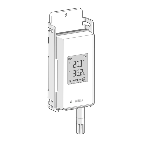
RFL100 User Guide M211861EN-D 2.2 RFL100 parts Figure 2 Front and display Service port connection indicator Battery level indicator Currently measured values Connection indicators Status LED. Blinks green for normal operation, red for error or alarm. Signal strength of access point connection Alarm indicators. -
Page 13: Figure 4 Rear And Inside
Chapter 2 – Product overview Figure 4 Rear and inside Type label On/off switch Clock battery Probe orientation mark. When connecting the probe, line up the markings on the probe and above the connector before pushing the probe to the connector. Humidity and/or temperature sensors under the filter Release button. -
Page 14: Table 3 Battery Level Indicator
RFL100 User Guide M211861EN-D 2.3 RFL100 batteries Main batteries RFL100 data logger is powered by two AA size primary (non-rechargeable) batteries with 1.5 V nominal voltage. Operation of the data logger always requires that compatible batteries with sufficient voltage are in place. When replacing batteries, always use new batteries, not partially discharged ones. -
Page 15: Table 4 Symbols
Chapter 2 – Product overview Symbol on display Description Battery voltage is too low to support radio communication. Data logging continues locally for 2 … 4 weeks until battery voltage is too low. The last bar of the battery symbol is flashing and error code Err 103 is shown on the display. - Page 16 RFL100 User Guide M211861EN-D Symbols on display Description Data logger is successfully connected to an access point, and connection between the access point and viewLinc server is also OK. The viewLinc symbol is flashing to indicate that the data logger is waiting to be accepted to the viewLinc system as a new device.
-
Page 17: Table 6 Signal Strength Indicator
Chapter 2 – Product overview Full connectivity: Data logger has discovered a viewLinc Enterprise Server and is connected to it through the access point. You can now log in to the viewLinc Enterprise Server and accept the device to the system. 2.5 Signal strength indicator Signal strength indicator shows the strength of the signal from the currently connected access point. -
Page 18: Figure 6 Alarm Indicators On Rfl100 Display
RFL100 User Guide M211861EN-D 2.6 Alarm indicators Figure 6 Alarm indicators on RFL100 display Alarm indicators for channel 1 Alarm indicators for channel 2 Table 7 Alarm symbols Symbol on display Description High-high threshold alarm active. High threshold alarm active. Alarm bell symbol that is always shown when any threshold alarm is active on this channel. -
Page 19: Figure 7 Rfl100 With High Alarm Active On Channel 1
Chapter 2 – Product overview RFL100 does not implement the Alarm Delay and Alarm off margin settings of viewLinc threshold alarms. Local alarm status on RFL100 changes as soon as the measured values cross the thresholds. 2.6.1 Alarm examples Figure 7 RFL100 with high alarm active on channel 1 Figure 8 RFL100 with high-high alarm active on channel 1 2.7 Service port The service port of the data logger provides a local interface for performing service actions... -
Page 20: Table 8 Specifications For A Usb Power Supply
2.7.1 Files and folders in USB filesystem Following files and folders are present in the USB filesystem of the data logger. Vaisala support may request files from the data logger to help with solving your support request. - Page 21 Chapter 2 – Product overview Path and file Content \Data\Log\Log_1h.txt Measurement data from the past hour. \Data\Log\Log_24h.txt Measurement data from the past 24 hours. \Data\Log\Log_30d.txt Measurement data from the past 30 days. \Data\Update\ Folder for firmware update. Copy the firmware update file here to start the update.
- Page 22 2.10 ESD protection Electrostatic discharge (ESD) can cause immediate or latent damage to electronic circuits. Vaisala products are adequately protected against ESD for their intended use. However, it is possible to damage the product by delivering an electrostatic discharge when touching, removing or inserting any objects inside the equipment housing.
-
Page 23: Open The Battery Cover Of The Data Logger
Chapter 3 – Installation 3. Installation 3.1 Setting up RFL100 Start the installation of the RFL100 by performing the appropriate setup procedure and verifying its operation: • If you are connecting a single probe, see Setup with one probe (page 21). • If you are connecting two temperature probes using the probe splitter accessory, see Setup with two temperature probes (page 23). -
Page 24: Figure 9 Detection Of A New Rh + T Probe
RFL100 User Guide M211861EN-D 4. If a probe is not already connected to the data logger, connect it now: • To connect a probe directly to the data logger, first align the orientation mark on the probe with the line above the probe connector. Then push the probe in all the way, do not rotate. - Page 25 Numbering labels for TMP115 probes (included in the probe mounting accessories) • Two temperature-only probes of following models: HMP110T, HMP115T and TMP115 (any combination) • Probe splitter (Vaisala item code CBL210834) • Optional: extension cable(s), to be connected between the probe splitter and probe •...
-
Page 26: Move The Power Switch To The Off Position
RFL100 User Guide M211861EN-D CAUTION! Make sure the components of your viewLinc Monitoring System are updated to the required firmware and software levels before setting up any RFL100 data loggers for two probe operation. 1. If any cable is connected to the service port of the data logger, disconnect it. 2. - Page 27 Chapter 3 – Installation 12. Look at the display and wait for the data logger to start up. You should see the word NEW on channel 2 for a few seconds, after which it is replaced by the temperature reading. 13.
-
Page 28: Figure 10 Rfl100 Mounting Methods
RFL100 User Guide M211861EN-D 3.2 Mounting RFL100 [in] Figure 10 RFL100 mounting methods Mounting with screws. Screws and wall plugs are included with the data logger. Mounting with cable ties. Cable ties are included with the data logger. Magnetic mounting (with optional magnetic mounting bracket) Mounting with a hook (hook not included) - Page 29 Chapter 3 – Installation 1. Select a suitable mounting location. A good location is easily accessible, protected from water and condensation, and remains within the operating temperature range of RFL100: • +2 ... +60 °C (+35.6 ... +140 °F) with alkaline batteries •...
-
Page 30: Figure 11 Probe Holder Asm213382 Parts
One probe holder is included in the RFL100 data logger package for each cable mounted probe. Additional probe holders are available as an accessory (Vaisala item ASM213382SP, includes 5 probe holders). Figure 12 HMP110 probe in probe holder ASM213382... -
Page 31: Figure 13 Hmp110 Probe
Chapter 3 – Installation 3.3.2 Mounting HMP110 probes Robust stainless steel probe for humidity and temperature measurement in demanding conditions. Suitable for measurement inside chambers, fridges, and freezers in temperature range -40 ... +80 °C (-40 ... +176 °F). Must be connected using a cable, as the probe is not designed to be integrated with RFL100 housing. -
Page 32: Figure 15 Tmp115 Probe
RFL100 User Guide M211861EN-D 3.3.4 Mounting TMP115 probes Wide-range temperature-only probe for measurement in extreme conditions. Probe body can be integrated with RFL100 or connected using a cable. Sensor tip is permanently connected to the probe body with a thin cable. Available as 50 cm (1 ft 7.7 in) and 3 m (9.8 ft) long versions. Figure 15 TMP115 probe If using a probe holder, align it to this groove. -
Page 33: Figure 16 Detection Of A New Rh + T Probe Shown On Display
Chapter 4 – Operation 4. Operation 4.1 Probe detection Probe detection of RFL100 has been changed to accommodate two probe operation. In firmware version 1.2.0 and later, the data logger detects and validates the connected probe(s) only at startup. If any unsupported probes or probe combinations are detected, or if both probes have been replaced simultaneously in two probe use, an error is shown. - Page 34 RFL100 User Guide M211861EN-D In the Info mode: • Display and LED are turned on if they have been turned off remotely. • Data logger starts radio scanning immediately if it has shut down to save power. • After showing the current measurement results and possible error codes, the data logger shows the text INFO ON and the following additional information: •...
-
Page 35: Figure 17 Rfl100 Remote Management Using Viewlinc Enterprise Server
Chapter 4 – Operation 4. Close the plug over the service port. 4.3 Remote management After an RFL100 data logger has been accepted to a viewLinc Monitoring System, it can be remotely managed using viewLinc Enterprise Server software. Remote management operations can be performed directly from the Sites Manager > Hosts and Devices tree. Figure 17 RFL100 remote management using viewLinc Enterprise Server Select Configure >... -
Page 36: Figure 18 Rfl100 Device Properties In Viewlinc
RFL100 User Guide M211861EN-D Figure 18 RFL100 device properties in viewLinc Local alarms on the RFL100 are also managed remotely, but in a different way. See Alarm indicators (page 16). viewLinc automatically issues calibration reminder notifications at 3 months and 1 month before to the due date, and again on the due date. - Page 37 Chapter 4 – Operation Measurement and data logging is not affected by the release procedure. Existing data will remain unaffected on the data logger. All remotely managed RFL100 settings will be reset to defaults: threshold alarm indicators will be cleared, and display and LED will turn on if they have been remotely turned off.
-
Page 38: Figure 19 Hmp115 Probe In Insight Software
Download Vaisala Insight software at www.vaisala.com/insight. The supported operating systems are Windows 7 (64-bit), Windows 8.1 (64-bit), and Windows 10 (64-bit). You need a Vaisala USB cable (order code 219690) to connect the probe to your computer. More information ‣ Adjusting measurement using Insight software (page 52) -
Page 39: Figure 20 Connecting Probe To Insight
Chapter 4 – Operation 4.5.1 Connecting probe to Insight software Figure 20 Connecting probe to insight • Computer with Microsoft Windowsâ operating system and Vaisala Insight software installed • USB connection cable (order code 219690) 1. Disconnect the probe from the data logger. - Page 40 RFL100 User Guide M211861EN-D 5. Maintenance 5.1 Cleaning RFL100 • Lint-free cloth • Isopropyl alcohol (70 %) Do not spray anything directly on the RFL100, since that may deposit impurities on the sensor. 1. Remove the data logger from the mounting bracket. 2.
- Page 41 Chapter 5 – Maintenance More information ‣ Accessories and spare parts (page 66) 5.3 Probe replacement Separate procedures for probe replacement are provided for different scenarios: • Replacing a probe when one probe is connected (page 40) • Replacing probes when two probes are connected (page 42) •...
- Page 42 RFL100 User Guide M211861EN-D 5.3.2 Replacing a probe when one probe is connected 1. Remove the data logger from the mounting bracket. 2. Open the battery cover of the data logger. 3. Move the power switch to the Off position. 4. To replace a fixed probe (directly connected to RFL100 without a cable): Orientation mark on data logger Orientation mark on probe a.
-
Page 43: Close The Battery Cover Of The Data Logger. Push The Latch Down Until You Hear A Click. If
Chapter 5 – Maintenance 5. To replace a cabled probe: Locking ring on probe cable a. Loosen the locking ring of the connector at the end of the probe cable, and pull the old probe away from the connector. b. Connect the new probe and tighten the locking ring. 6. - Page 44 RFL100 User Guide M211861EN-D 5.3.3 Replacing probes when two probes are connected You can replace one or both of the probes by following the procedure below. Only temperature probes are supported in two probe mode. 1. Remove the data logger from the mounting bracket. 2.
- Page 45 RFL100 automatically sends the new information to viewLinc. The calibration frequency depends on the application and your compliance requirements. Vaisala recommends having the probe calibrated and adjusted once a year by Vaisala Calibration and Repair Services. See www.vaisala.com/calibration. Generic procedures for on-site calibration and adjustment are provided in this guide:...
-
Page 46: Table 10 Measurement Adjustments Of Rfl100-Compatible Probes
See Field checking using a reference instrument (page 45). • To calibrate and adjust the probe using a Vaisala handheld meter and humidity and temperature references, see Calibration and adjustment using HM40 (page 45) Calibration and adjustment using MI70 (page 50). - Page 47 °F). When comparison against a calibrated reference indicates that adjustment of humidity measurement is necessary, Vaisala recommends adjusting in two points, 11 %RH and 75 %RH. These humidities can be produced using LiCl and NaCl salt chambers of the Vaisala HMK15 Humidity Calibrator.
- Page 48 RFL100 User Guide M211861EN-D 6. Select the parameter to be calibrated at menu item [1] Quantity. 7. Select number of calibration points at menu item [2] Point count. 8. Place the probe in the first reference environment (first calibration point). Wait 20 – 40 minutes for the reading to stabilize.
- Page 49 Chapter 5 – Maintenance 9. Select [3] Point 1 > Set. The meter now shows the currently measured value of the selected parameter. Set the reference value using the arrow buttons and select OK. Correction to measurement at point 1 is now shown in the text for menu item [3] Point 1. If you are only doing a 1-point calibration, skip to step 10.
- Page 50 RFL100 User Guide M211861EN-D 11. Select [4] Point 2 > Set The meter now shows the currently measured value of the selected parameter. Set the reference value using the arrow buttons and select OK. Correction to measurement at point 2 is now shown in the text for the menu item [4] Point 2.
- Page 51 Chapter 5 – Maintenance 12. Select [5] Note to edit the calibration info text that will be stored in the probe when the adjustment is applied in step 13. Edit the text using the select button and arrow keys. When done, select the OK character in the bottom right corner. To exit without changing the text, select Cancel.
- Page 52 You can calibrate and adjust the probe of your RFL100 data logger in one or two points using the MI70 indicator. You can also do the 1-point calibration so that you compare the reading of the probe to any MI70-compatible Vaisala probe that provides the same measurement parameter.
- Page 53 Chapter 5 – Maintenance 11. To perform the adjustment using two reference environments (two-point adjustment), perform these steps: a. Select 2-point adjustment > SELECT > OK. b. When the measurement is stable, select READY. c. Give the reference RH value by using the arrow buttons and select OK. d.
-
Page 54: Figure 21 Adjusting Relative Humidity Measurement In Insight
M211861EN-D 5.4.6 Adjusting measurement using Insight software Figure 21 Adjusting relative humidity measurement in Insight • Computer with Windows operating system and Vaisala Insight software installed • Vaisala USB cable 219690 for connecting the probe • Reference environments for the desired calibration and adjustment points (see... - Page 55 11. Disconnect the probe from the USB cable. 12. Connect the probe to the data logger. More information ‣ Vaisala Insight software (page 36) ‣ Probe replacement (page 39) 5.5 Changing RFL100 batteries • 2 pcs of new AA size 1.5 V batteries: alkaline (type LR6) or lithium (type FR6) 1.
-
Page 56: Downloading Data Using Service Port
• Computer with a free USB port and an operating system that supports the Media Transfer Protocol (MTP). For example, Windowsâ 7 and newer. • USB connection cable (USB 2.0 type A - micro-B, Vaisala cable 244961). You can also use a generic cable that has all pins connected (not just power). -
Page 57: Open The Plug That Covers The Service Port
RFL100. After the computer detects the RFL100 and installs the appropriate driver, it is available for file transfer. 4. Copy the firmware update file supplied by Vaisala into the \Data\Update folder on the RFL100. Select to overwrite the old file when prompted by your computer. -
Page 58: Table 11 Troubleshooting Table
RFL100 User Guide M211861EN-D 6. Troubleshooting 6.1 Problem situations Table 11 Troubleshooting table Problem Possible cause Solution Display shows one or more Various causes. Check meaning of the error error codes. code(s) and proceed accordingly. See Error codes (page 57). You are adding a new RFL100 RFL100 is not in range of an Turn on installation mode in an data logger to the system but it... -
Page 59: Table 12 Rfl100 Error Codes
Error code Cause Recommended action Err 100 User parameter bank checksum failure. Power cycle the data logger. If the error persists, contact Vaisala. Err 101 Factory parameter bank checksum failure. Err 102 Real-time clock of the data logger has Restore the wireless connection to an lost accurate time. - Page 60 Real-time clock temperature If error code Err 200 is also active, compensation problem. replace the clock battery. If the error persists, contact Vaisala. More information ‣ Probe detection (page 31) ‣ Probe replacement (page 39) ‣ Changing RFL100 clock battery (page 54)
- Page 61 • Computer with a free USB port and an operating system that supports the Media Transfer Protocol (MTP). For example, Windowsâ 7 and newer. • USB connection cable (USB 2.0 type A - micro-B, Vaisala cable 244961). You can also use a generic cable that has all pins connected (not just power).
- Page 62 • Factory reset can be done in an attempt to recover from serious operating errors that prevent normal startup or operation. This is not typically necessary, and should only be done in cases where it is advised by troubleshooting instructions or Vaisala Support. 1. Open the battery cover of the data logger.
-
Page 63: Table 13 Wireless
Chapter 7 – Technical data 7. Technical data 7.1 RFL100 technical specification Table 13 Wireless Property Specification Networking standards Vaisala VaiNet Modulation LoRa ™ chirp spread spectrum modulation Output power 14 dBm (25 mW) Antenna Internal Typical range (indoors) At least 100 m (328 ft) -
Page 64: Table 15 Operating Environment
RFL100 User Guide M211861EN-D Table 15 Operating environment Property Description/Value Storage temperature −40 … +60 °C (−40 … +140 °F) Operating humidity 0 … 100 %RH, non-condensing EMC compliance EN/IEC 61326-1, industrial environment Operating temperature with alkaline batteries +2 … +60 °C (+35.6 … +140 °F) with lithium batteries −20 …... -
Page 65: Table 18 Hmp110/T Probe Measurement Performance
Chapter 7 – Technical data Property Specification With mounting bracket 186 × 68 × 36.5 mm (7.32 × 2.68 × 1.44 in) Weight With batteries (2 pcs alkaline) and HMP115 probe 190 g (6.7 oz) With batteries (2 pcs alkaline), HMP115 probe, 254 g (8.96 oz) and magnetic mounting bracket Materials... -
Page 66: Table 19 Hmp115/T Probe Measurement Performance
RFL100 User Guide M211861EN-D Property Description/Value at 0 … +40 °C (+32 °F … +104 °F) ± 0.2 °C (0.36 °F) at −40 … 0 °C, +40 … +80 °C (−40 … +32 °F, +104 ± 0.4 °C (0.72 °F) …... -
Page 67: Table 20 Tmp115 Probe Measurement Performance
Chapter 7 – Technical data Property Description/Value Temperature sensor Pt1000 RTD Class F0.1 IEC 60751 Includes non-linearity, hysteresis, and repeatability. Small variations possible; see also calibration certificate. Table 20 TMP115 probe measurement performance Property Description/Value Temperature Measurement range −196 … +90 °C (−320.8 … +194 °F) Accuracy over temperature range at −196 …... -
Page 68: Table 22 Hmp115/T Probe Mechanical Specifications
RFL100 User Guide M211861EN-D Table 22 HMP115/T probe mechanical specifications Property Specification IP rating IP54 Diameter 14 mm (0.55 in) Length 79 mm (3.11 in) Materials Probe body PC/ABS blend Grid filter PC (glass reinforced) Sleeve PC/ABS blend Table 23 TMP115 probe mechanical specifications Property Specification IP rating... -
Page 69: Table 25 Rfl100 Spare Parts
CBL210834 T probes Requires at least RFL100 firmware version 1.2.0, AP10 firmware version 3.0, and viewLinc 5.0.2. Table 25 RFL100 spare parts Description Vaisala item code Mounting bracket (5 pcs) DRW244769SP Magnetic mounting bracket (5 pcs) ASM211527SP Battery cover (5 pcs) -
Page 70: Figure 22 Rfl100 Dimensions With Mounting Bracket
RFL100 User Guide M211861EN-D Description Vaisala item code Sintered stainless steel filter HM46670SP PTFE filter DRW244938SP Table 27 HMP115/T probe spare parts Description Vaisala item code Plastic grid filter DRW240185SP Plastic grid with membrane filter ASM210856SP PTFE filter 219452SP 7.4 Dimension drawings 36.5 [1.44]... -
Page 71: Figure 23 Rfl100 Dimensions Without Mounting Bracket
Chapter 7 – Technical data 62 [2.4] 31 [1.22] Ø 12 [0.47] [in] Figure 23 RFL100 dimensions without mounting bracket 68 [2.68] Ø 6 [0.23] Ø 3.80 [0.15] Ø 3.80 [0.15] [in] Figure 24 RFL100 mounting bracket dimensions... -
Page 72: Figure 25 Hmp110 Probe Dimensions
RFL100 User Guide M211861EN-D 71 [2.8] [in] Figure 25 HMP110 probe dimensions 79.5 [3.12] 24.5 [0.96] [0.14] [in] Figure 26 HMP115 probe dimensions 0.5 m [19.7] or 3 m [118.1] 69.7 [2.74] 50.8 [2] [0.14] [in] Figure 27 TMP115 probe dimensions... - Page 73 Technical support Contact Vaisala technical support at helpdesk@vaisala.com. Provide at least the following supporting information as applicable: • Product name, model, and serial number • Software/Firmware version • Name and location of the installation site • Name and contact information of a technical person who can provide further information on the problem For more information, see www.vaisala.com/support.
- Page 76 www. v aisala.com...
Need help?
Do you have a question about the VaiNet RFL100 and is the answer not in the manual?
Questions and answers