Vaisala HMT140 User Manual
Vaisala wi-fi data logger
Hide thumbs
Also See for HMT140:
- Quick manual (97 pages) ,
- User manual (70 pages) ,
- Quick manual (78 pages)
Table of Contents
Advertisement
Quick Links
Download this manual
See also:
Quick Manual
Advertisement
Table of Contents

Related Manuals for Vaisala HMT140


Summary of Contents for Vaisala HMT140
- Page 1 M211488EN-G User Guide Vaisala Wi-Fi Data Logger HMT140...
- Page 2 Vaisala Oyj Vanha Nurmijärventie 21, FI-01670 Vantaa, Finland P.O. Box 26, FI-00421 Helsinki, Finland +358 9 8949 1 Visit our Internet pages at www.vaisala.com. © Vaisala Oyj 2019 users. All legally binding No part of this document may be obligations and agreements are...
-
Page 3: Table Of Contents
Fixed or Remote Probe................10 2.1.5 Interchangeable Probe................10 2.1.6 Optional Display..................11 HMT140 Components..................12 2.2.1 Installation Kit................... 12 2.2.2 HMT140 Utility and Configuration Cable..........13 2.2.3 Connections and Wiring................14 Safety........................ 16 2.3.1 ESD Protection..................17 Regulatory Compliances.................17 2.4.1 FCC Compliance Statement..............18 2.4.2... - Page 4 HMT140 User Guide M211488EN-G HMT140 Function Modes................33 4.3.1 Operating Modes..................33 4.3.2 Transmission of Data................34 4.3.3 Transmit Attempts.................. 34 4.3.4 Alarm-triggered Transmission...............34 Additional Settings..................35 4.4.1 Change Input/Output Scale..............35 4.4.2 Save and Recall Settings................ 36 4.4.3 Delete Saved Settings................36 4.4.4...
- Page 5 Table of Contents Recycling......................65...
- Page 6 Optional Probe Mounting Flange..............24 Figure 13 Optional Probe Mounting Clamp..............24 Figure 14 Fixed Probe Model...................46 Figure 15 Remote Probe Model..................47 Figure 16 HMT140 Fixed Probe Dimensions in mm (in)...........54 Figure 17 HMT140 Remote Probe Dimensions in mm (in)........55...
- Page 7 List of Tables List of Tables Table 1 Document Versions (English)................7 Table 2 Related Manuals....................7 Table 3 Connect Time Components ................38 Table 4 HUMICAPâ Humidity and Temperature Probe HMP110......56 Table 5 Temperature Probes..................56 Table 6 Analog Inputs...................... 57 Table 7 Measurement Variants..................
- Page 8 HMT140 User Guide M211488EN-G...
-
Page 9: About This Document
Chapter 1 – About This Document 1. About This Document 1.1 Version Information This document provides information for installing, operating, and maintaining the Vaisala Wi-Fi Data Logger HMT140. It also details the operation of the Vaisala HMT140 Utility software. Table 1 Document Versions (English) Document Code Date... -
Page 10: Trademarks
Indicates that you need to take some notes during the task. 1.4 Trademarks Vaisalaâ and HUMICAPâ are registered trademarks of Vaisala Oyj. All other product or company names that may be mentioned in this publication are trade names, trademarks, or registered trademarks of their respective owners. -
Page 11: Product Overview
An HMT140 can store several thousands of records before needing to overwrite data. In the event of a communication problem, the HMT140 will continue to log and store data until it has collected 3060 records per channel and then it will begin overwriting data. -
Page 12: Options And Accessories
• Stainless steel sintered filter HM46670SP 2.1.4 Fixed or Remote Probe The HMT140 is available either with a fixed probe directly attached to the housing or a remote probe with different cable lengths (3/5/10 m (9.8/16.4/32.8 ft)). Extension cables can be easily cascaded in order to obtain longer reach, to a maximum length of 10 m (32.8 ft). -
Page 13: Optional Display
• Order a new probe and return the old one to Vaisala (replacement probe). Only probes that have a compatible digital output (VDIGI mode) can be used with the HMT140. Compatible probes have the letter "V" as the first letter in their order code. The order code is written on the probe. -
Page 14: Hmt140 Components
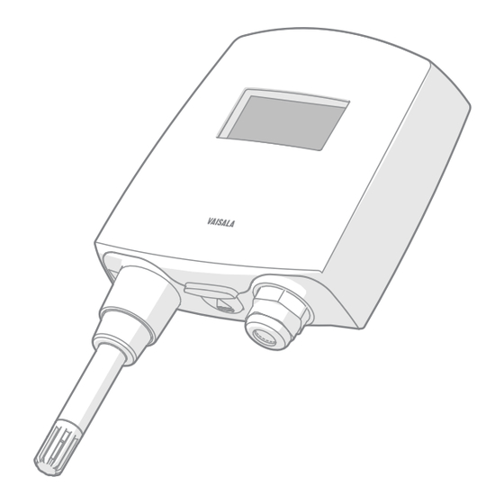
M211488EN-G 2.2 HMT140 Components The following figure illustrates the main features of the HMT140. On the left is a remote probe model without display, and on the right is a fixed probe model with the optional display. The numbers and arrows indicate the main components of the HMT140 models. -
Page 15: Hmt140 Utility And Configuration Cable
‣ Wall Mounting (page 20) 2.2.2 HMT140 Utility and Configuration Cable To connect an HMT140 to your network, install the HMT140 Utility software and connect the HMT140 to your PC with the HMT140 Configuration Cable (software and cable shipped with viewLinc). -
Page 16: Connections And Wiring
HMT140 User Guide M211488EN-G 2.2.3 Connections and Wiring Figure 2 HMT140 Components Diagram... -
Page 17: Figure 3 Rtd Wiring Diagram
Chapter 2 – Product Overview Figure 3 RTD Wiring Diagram Figure 4 RTD and Boolean Wiring Diagram Figure 5 Boolean Wiring Diagram... -
Page 18: Safety
HMT140 User Guide M211488EN-G Figure 6 Voltage Wiring Diagram Figure 7 Current Wiring Diagram 2.3 Safety This product has been tested for safety. Note the following precautions: WARNING! Remove batteries before shipping. CAUTION! Do not modify the unit or use it in ways not described in the documentation. -
Page 19: Esd Protection
The HMT140 contains a radio module with the following module approvals: • FCC ID: U3O-G2M5477 • IC ID: 8169A-G2M5477 • NCC ID: CCAF11LP0240T6 • 当該機器には電波法に基づく、技術基準適合証明等を受けた特定無線 R 201-125765 設備を装着している。 EN 61326-1B and EN 301 489-1 apply only to the EU specific versions of HMT140 loggers with CE marking. -
Page 20: Fcc Compliance Statement
HMT140 User Guide M211488EN-G 2.4.1 FCC Compliance Statement This equipment has been tested and found to comply with the limits for a Class B digital device, pursuant to Part 15 of the FCC rules. These limits are designed to provide reasonable protection against harmful interference in a residential installation. -
Page 21: Installation
Note that you can complete the configuration and setup procedures after mounting with a portable PC. To connect the HMT140 to your network and view HMT140 data using viewLinc, you require HMT140 Utility software and an HMT140 Configuration Cable (shipped with viewLinc). -
Page 22: Wall Mounting
1. Open the HMT140 cover. 2. Make sure that the HMT140 is correctly aligned and attach it directly to the wall with up to four screws (not included in the package). Select the size and type of the fastening screws according to the wall material (for example, wood or stone). -
Page 23: Figure 9 Mounting Diagram
[in] Figure 9 Mounting Diagram Vaisala strongly recommends you to use all four screws; however, the HMT140 enclosure fastening holes are initially covered with a thin plastic membrane, so less than four screws could also be used without sacrificing the ingress protection... -
Page 24: Duct Installation
M211488EN-G 3.1.3 Duct Installation The duct installation kit includes a plastic pipe with a flange (Vaisala order code: 215619). To install the HMP110 probe with the duct installation kit, drill a hole into the duct wall, assemble the probe to the duct installation kit, slide the probe head through the hole, and attach the flange to the duct wall with four screws. -
Page 25: Figure 11 Dimensions Of Hmp110 Probe With Duct Installation Kit
Chapter 3 – Installation Mounting screw Tension screw HMP110 assembled in duct installation kit plastic pipe To attach the probe assembly to the duct: 1. Drill the holes for the duct installation kit as follows: • Use a 24-mm (0.9-in) drill bit to drill a hole in the wall. •... -
Page 26: Optional Mounting Accessories
Figure 12 Optional Probe Mounting Flange 3.2.2 Probe Mounting Clamp The optional mounting clamp (Vaisala order code: 226067) makes it easy to install the probe on the wall of the measurement environment. The probe can be detached for calibration simply by loosening the lower screw. -
Page 27: Set Up And Operation
6. When the installation is complete, disconnect the cable from your PC. You are now ready to set up and configure your device. If you wish to remove the Vaisala HMT140 Utility software at a later date, use the uninstall function in the Windows Control Panel. -
Page 28: Configuring The Hmt140 To Your Network
1. Make sure that the HMT140 cover is open and the correct batteries are installed. 2. Turn on the HMT140 and wait five seconds to make sure the startup process completes. 3. Plug the USB connector on the HMT140 Configuration Cable to the computer, if it is not already connected. - Page 29 7. Click Retrieve again to force retrieval of current settings. The connected type is identified in the upper right corner of the Setup tab window. The status bar is located at the bottom of the HMT140 Utility window. It contains the following panels: •...
-
Page 30: Setup Consideration
1. Make sure the HMT140 cover is open and the correct batteries are installed. 2. Turn on the HMT140 and wait five seconds to make sure the startup process completes. 3. Plug the USB connector on the HMT140 Configuration Cable to the computer, if it is not already connected. - Page 31 Chapter 4 – Set Up and Operation 7. On the Sensor tab, select from the following options: • Transmit Period: Select how frequently the HMT140 transmits data. In the event of an alarm condition, transmission frequency is overridden automatically. If you require a faster transmit period, the HMT140 Utility version 1.1.4.0 and higher provide additional...
- Page 32 Beeper (whether you want to be able to turn the Beeper on or off with the push button on the HMT140). It is also possible to turn the Beeper on and off by holding down the SERVICE button for approximately five seconds.
-
Page 33: Modify Hmt140 Description
Optional: Enter a name for the saved settings on the Set up tab in the Saved Settings field and click the disk icon to save. If the HMT140 is used with more than one wireless network, enter a name in the Saved Network Settings field and click Save. Other network settings files can be saved and recalled from the Saved Settings field. - Page 34 M211488EN-G To monitor the transmission status: 1. On the Status tab, click Get to update the HMT140 Utility window with the latest status information: IP settings, WLAN and Sensor battery. If successful, the HMT140 Utility displays the information on the Status page.
-
Page 35: Hmt140 Function Modes
• Channel: This is the channel found during the Channel Auto Find feature or the channel set in the Setup page. If the HMT140 cannot find a channel when in Auto Find mode, the utility will display “none”. -
Page 36: Transmission Of Data
In Transmitter mode, the HMT140 spends most of its time in a very low power state (sleep) to save battery power. When a transmit period is due, it powers up the radio, attempts to link to the specified wireless network, transmits its data and then goes back to sleep. -
Page 37: Additional Settings
HighHigh or LowLow threshold alarm settings. The HMT140 can also be configured to initiate a Transmit Attempt when it exits an alarm state. Refer to the Vaisala viewLinc User Guide for information about alarm settings. -
Page 38: Save And Recall Settings
1. On the Status tab, click Restart. 4.4.5 Get General Information To gather general information about the HMT140, select the Info tab and then click Get. The HMT140 Utility will retrieve the following information: • MAC address • Firmware version •... -
Page 39: Units And Temperature
1. Turn off the HMT140. Make sure the Configuration Cable is disconnected. 2. After replacing batteries, press and hold the SERVICE button. • Turn the HMT140 power switch on while the SERVICE button is engaged. • Wait approximately 10 seconds until the LED light flashes and you hear several beeps. -
Page 40: Connection Performance
4.5.3 Connection Performance Consistent connection performance is essential for longevity of battery life. The HMT140 Utility can perform a test to indicate how well the HMT140 connects to the network, which provides an indication about the expected battery life. If the average connection time is more than five seconds, the HMT140 may not connect consistently and the battery may be exhausted before the battery meter indicates. -
Page 41: Advanced Options
Chapter 4 – Set Up and Operation 3. Select the Tools tab. In the Test Connect Time area, click Start. The HMT140 Utility will repeatedly attempt to connect to the network with one second between connection attempts. You can then view: •... -
Page 42: Passwords
• Data Rate: The default data rate is 1 Mbit/sec. and can be set from one to 54 Mbit/sec. The lower the data rate the longer range the HMT140 will have. The 802.11b data rates are: 1, 2, 5.5 and 11. All other data rates are 802.11g data rates. An access point or wireless router may be configured to exclude 802.11b data rates. -
Page 43: Set Up A New Channel
4.6.2 Set Up a New Channel On the Network tab, you can select a specific channel to view, using the Channel field. To select multiple channels for the HMT140 to search when connecting to an access point or a wireless router, select Auto Find. -
Page 44: Find Additional Networks
1. On the Setup tab, on the Network page, click the Find Networks button to scan for all available wireless networks. The HMT140 Utility displays details about the currently available networks: SSID: SSID of the access point or router (wireless channel). -
Page 45: Test Network Connectivity
Ping from This PC When the Ping From This PC button is clicked, the HMT140 will use either the IP address in the IP Address field or the current address in the Destination IP field in the Setup tab and ping that specified address from the local PC. - Page 46 HMT140 User Guide M211488EN-G 4. To modify the default UDP port (default is 6767): code [Settings] DefaultPort=6767 5. To specify the auto find channels: [Settings] ChannelMask=1,2,3,4,5,6,7,8,9,10,11 6. Restart the HMT140 Utility to apply the changes.
-
Page 47: Maintenance
1. Loosen the metal locking bushing by carefully turning it counter clockwise. 2. Remove the probe from the HMT140 by pulling it gently outwards. 3. Attach the new probe to the 4-pin M8 panel connector on the HMT140 (only one position possible). -
Page 48: Remote Probe Model
HMT140 User Guide M211488EN-G 4. Tighten the locking bushing to the M8 panel connector by turning it clockwise. Figure 14 Fixed Probe Model Holder bushing (attached permanently to the probe) HMP110 probe Locking bushing 5.2.2 Remote Probe Model To remove and replace a remote probe: 1. -
Page 49: Calibration And Adjustment
Sleeve securing the probe to the cable HMP110 probe 5.3 Calibration and Adjustment HMP110 probe calibration status can be viewed with the HMT140 Utility. Calibration settings are adjusted using viewLinc. To view probe calibration status: 1. On the Info tab, click Get. This page will display calibration information including calibration date, calibrator, and next calibration due date. -
Page 50: Battery Replacement
When replacing batteries, it is important to use new, recommended batteries and to reset the battery meter to make sure an accurate estimate of battery life remaining. To replace the batteries and reset the battery meter of the HMT140: 1. Open the HMT140 cover. -
Page 51: Troubleshooting
The HMT140 works best with signal strengths above -63 dBm (for 802.11b mode) and -75 dBm (for 802.11g mode). If the signal strength is less, the HMT140 may work marginally or not at all. Stronger signal strength improves transmission performance. -
Page 52: Transmit Cycle
2. Verify that you are connected to the right network. 3. Use the Ping from PC function in the HMT140 Utility to see if your PC can ping an address on that network (your PC must be connected to that network). - Page 53 Chapter 6 – Troubleshooting 4. Use the Ping from PC function in the HMT140 Utility (if this PC is connected) and see if you can ping the HMT140 when it is in Config mode. Go to the Status tab to determine the IP address.
- Page 54 HMT140 User Guide M211488EN-G 3. Use the Test Connect Time tool in the utility to verify how long the HMT140 takes to connect to the network. If the network consistently takes longer than five seconds to connect to the network, you may need to make adjustments to the settings.
- Page 55 5. Check transmission attempts. Is the setting for number of tries too high? 6. Check network quality. Is the connect time for the HMT140 greater than five seconds? Use the Test Connect Time tool in the HMT140 Utility.
-
Page 56: Technical Data
HMT140 User Guide M211488EN-G 7. Technical Data 7.1 HMT140 Dimensions (Fixed Probe) 37 [1.46] 120 [4.72] Ø 12 [0.47] Figure 16 HMT140 Fixed Probe Dimensions in mm (in) -
Page 57: Hmt140 Dimensions (Remote Probe)
Chapter 7 – Technical Data 7.2 HMT140 Dimensions (Remote Probe) 37 [1.46] 120 [4.72] Ø 12 [0.47] Figure 17 HMT140 Remote Probe Dimensions in mm (in) -
Page 58: Hmt140 Product Specifications
HMT140 User Guide M211488EN-G 7.3 HMT140 Product Specifications Table 4 HUMICAPâ Humidity and Temperature Probe HMP110 Property Description/Value Relative Humidity Measurement range 0 ... 100 %RH Accuracy (incl. Non-Linearity, Hysteresis, and Repeatability): At temperature range 0 ... +40 °C (+32 ... +104 °F): 0 ... -
Page 59: Table 6 Analog Inputs
Chapter 7 – Technical Data Property Description/Value Input impedance 5.1K Ω Measurement range -196 ... +90 °C (-320.8 ... +194 °F) Accuracy over Temperature Range: -196 ... -90 °C (-320.8 ... -130 °F) ±2.5 °C (±4.5 °F) -90 ... -30 °C (-130 ... -22 °F) ±0.75 °C (±1.35 °F) -30 ... -
Page 60: Table 8 Operating Environment
HMT140 User Guide M211488EN-G Model Measurement Channels HMT147 2 Door Contacts HMT148 1 RTD Temperature and 1 Door Contact HMT14D 1 RTD Temperature and 1 Current Input (0 ... 20 mA) HMT14E 1 RTD Temperature and 1 Voltage Input (0 ... 5 VDC) HMT14F 1 RTD Temperature and 1 Voltage Input (0 ... -
Page 61: Table 11 Wireless
R 201-125765 明等を受けた特定無線設備を装着している。 Table 12 Standards Property Description/Value Electromagnetic compatibility EN 61326-1B, EN 301 489-1, EN 300 328 V2.1.1 Safety EN 61010-1 EN 61326-1B and EN 301 489-1 apply only to the EU specific versions of HMT140 loggers with CE marking. -
Page 62: Table 13 Spare Parts And Accessories
HMT140 User Guide M211488EN-G Region-specific standards and regulations are applied to wireless devices. The HMT140 logger versions with CE marking can be used in the following regions/ countries. The list is subject to change without prior notice. • EU countries •... - Page 63 Chapter 7 – Technical Data Item Order Code Four Dual Lock ™ Strips (76 mm/3 in) 237217SP See separate order form.
- Page 64 HMT140 User Guide M211488EN-G...
-
Page 65: Index
Index Index advanced options........39 HMT140 Auto Find Channels........ 41 components..........12 deleting settings........36 Fixed Probe Model......45 batteries getting information......36 connection performance....38 optional display........11 replacing..........48 overview.............9 battery life Remote Probe Model......46 checking..........36 restarting..........36 extending.........28, 36 HMT140Utility.INI file...... - Page 66 HMT140 User Guide M211488EN-G recording passwords......40 removing/fastening fixed probe..........45 remote probe........46 resetting battery meter......48 restarting a device........36 safety............16 Save/Recall Settings......36 settings deleting............36 specifications........... 56 troubleshooting........49 viewing battery status........36 calibration status........47...
-
Page 67: Warranty
Please see the applicable supply contract or Conditions of Sale for details of the warranty for each product. Technical Support Contact Vaisala technical support at helpdesk@vaisala.com. Provide at least the following supporting information: • Product name, model, and serial number •... - Page 68 HMT140 User Guide M211488EN-G...
- Page 70 www. v aisala.com...
Need help?
Do you have a question about the HMT140 and is the answer not in the manual?
Questions and answers