Vaisala RFL100 User Manual
Vainet wireless humidity and temperature data logger
Hide thumbs
Also See for RFL100:
- Quick manual (172 pages) ,
- User manual (76 pages) ,
- Quick manual (22 pages)

Related Manuals for Vaisala RFL100


Summary of Contents for Vaisala RFL100
- Page 1 M211861EN-A User Guide Vaisala VaiNet Wireless Humidity and Temperature Data Logger RFL100...
- Page 2 Street address: Vanha Nurmijärventie 21, FI-01670 Vantaa, Finland Mailing address: P.O. Box 26, FI-00421 Helsinki, Finland Phone: +358 9 8949 1 Visit our Internet pages at www.vaisala.com. © Vaisala 2018 obligations and agreements are No part of this manual may be...
-
Page 3: Table Of Contents
Mounting RFL100................... 20 Connection Indicators..................22 3.3.1 Connection Examples................23 Operation......................24 Remote Management..................24 Releasing RFL100 from a viewLinc Monitoring System......25 Speeding Up Radio Scanning Temporarily..........26 Maintenance....................28 Cleaning RFL100.....................28 Changing the Probe Filter................28 Disconnecting the Probe................29 Connecting the Probe..................29 Calibration and Adjustment................ - Page 4 RFL100 User Guide M211861EN-A Troubleshooting....................40 Problem Situations..................40 Error Codes...................... 41 Verifying Operation of RFL100..............42 Downloading Data Using Service Port............42 Technical Data....................44 RFL100 Technical Specification..............44 Spare Parts and Accessories.................48 RFL100 Dimensions..................49 Technical Support...................... 51 Warranty........................51...
- Page 5 Alarm Indicators on RFL100 Display............11 Figure 7 RFL100 with High Alarm Active on Channel 1...........12 Figure 8 RFL100 with High-High Alarm Active on Channel 1........ 12 Figure 9 RFL100 Mounting Methods................20 Figure 10 RFL100 Remote Management using viewLinc Enterprise Server..24 Figure 11 RFL100 Properties in viewLinc..............25...
- Page 6 Table 3 Battery Level Indicator..................10 Table 4 Alarm Symbols.....................11 Table 5 Specifications for a USB Power Supply............13 Table 6 Symbols Used in RFL100 Product Markings..........17 Table 7 Symbols........................22 Table 8 Connection States..................... 22 Table 9 Troubleshooting Table..................40 Table 10 RFL100 Error Codes..................
-
Page 7: About This Document
Chapter 1 – About This Document 1. About This Document 1.1 Version Information This document provides instructions for installing, using, and maintaining the RFL100 Data Logger. Table 1 Document Versions Document Code Date Description M211861EN-A May 2018 First version. 1.2 Related Manuals Table 2 Related Manuals... -
Page 8: Trademarks
Lists tools needed to perform the task. Indicates that you need to take some notes during the task. 1.4 Trademarks Vaisalaâ and HUMICAPâ are registered trademarks of Vaisala Oyj. The LoRa ™ name and associated logo are trademarks of Semtech Corporation or its subsidiaries. -
Page 9: Product Overview
Enterprise Server Figure 1 Connecting RFL100 to the viewLinc Monitoring System RFL100 requires a connection to a Vaisala AP10 Access Point. AP10 can connect up to 32 loggers to the viewLinc Monitoring System. In a typical indoor space, install the AP10 within 100 meters of the RFL100. -
Page 10: Rfl100 Parts
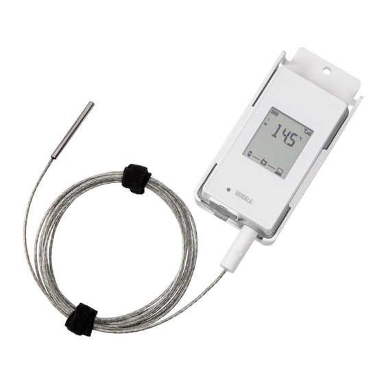
RFL100 User Guide M211861EN-A 2.2 RFL100 Parts Figure 2 Front and Display Service port connection indicator. Battery level indicator. Currently measured values. Connection indicators. Status LED. Blinks green for normal operation, red for error or alarm. Signal strength of access point connection. -
Page 11: Figure 4 Rear And Inside
Humidity and/or temperature sensors under the filter. Release button. Push to release RFL100 from its current viewLinc system, and allow it to connect to any viewLinc system. Main batteries. Use only non- rechargeable, AA size, 1.5 V alkaline (LR6) or lithium (FR6) batteries. -
Page 12: Rfl100 Batteries
Clock Battery RFL100 also has a separate 3 V lithium battery (type CR1/3N button cell) to keep the real-time clock powered when the device is otherwise turned off. This battery is good for 10 years, and should only be replaced if the data logger gives the low clock battery error. -
Page 13: Alarm Indicators
Low threshold alarm active. Low-low threshold alarm active. RFL100 can show active threshold alarms on its local display. When a threshold alarm is active on RFL100, the appropriate alarm indicators will be shown on the display. Additionally, the LED will flash red for high-high and low-low threshold alarms. -
Page 14: Alarm Examples
RFL100. On the RFL100, only one set of thresholds can be active at a time for one channel. The latest set that is pushed to the device replaces the previous one. The Send to device setting of any previously sent threshold alarm is automatically set to No. -
Page 15: Service Port
Chapter 2 – Product Overview 2.5 Service Port The service port of the data logger provides a local interface for performing service actions that cannot be done over the air, such as updating the device firmware. The service actions are based on file transfer using Media Transfer Protocol (MTP), so no special software is needed. The service port connector is a standard micro-USB connector. -
Page 16: Regulatory Compliance
Enterprise Server and access points first. You can manually wake up the radio of an RFL100 Data Logger by pressing its Refresh button. The button is located next to the service port under the silicone plug. -
Page 17: Ised Compliance Statement
съответствие може да се намери на следния интернет адрес: www.vaisala.com/ declarationofconformity CS: Tímto Vaisala Oyj prohlašuje, že typ rádiového zařízení RFL100 je v souladu se směrnicí 2014/53/EU. Úplné znění EU prohlášení o shodě je k dispozici na této internetové adrese: www.vaisala.com/declarationofconformity DA: Hermed erklærer Vaisala Oyj , at radioudstyrstypen RFL100 er i overensstemmelse med... - Page 18 Az EU-megfelelőségi nyilatkozat teljes szövege elérhető a következő internetes címen: www.vaisala.com/declarationofconformity IT: Il fabbricante, Vaisala Oyj , dichiara che il tipo di apparecchiatura radio RFL100 è conforme alla direttiva 2014/53/UE. Il testo completo della dichiarazione di conformità UE è disponibile al seguente indirizzo Internet: www.vaisala.com/declarationofconformity...
-
Page 19: Safety
Directiva 2014/53/UE. Textul integral al declarației UE de conformitate este disponibil la următoarea adresă internet: www.vaisala.com/declarationofconformity SK: Vaisala Oyj týmto vyhlasuje, že rádiové zariadenie typu RFL100 je v súlade so smernicou 2014/53/EÚ. Úplné EÚ vyhlásenie o zhode je k dispozícii na tejto internetovej adrese: www.vaisala.com/declarationofconformity SL: Vaisala Oyj potrjuje, da je tip radijske opreme RFL100 skladen z Direktivo 2014/53/EU. -
Page 20: Esd Protection
2.10 ESD Protection Electrostatic Discharge (ESD) can cause immediate or latent damage to electronic circuits. Vaisala products are adequately protected against ESD for their intended use. However, it is possible to damage the product by delivering an electrostatic discharge when touching, removing or inserting any objects inside the equipment housing. -
Page 21: Installation
In that case the display will show error code ERR 202. When you turn on the RFL100 it starts to scan for VaiNet access points that are in installation mode. RFL100 will connect to the access point with the best signal strength, and wait to be accepted by the administrator of the viewLinc Enterprise Server. -
Page 22: Mounting Rfl100
M211861EN-A 3.2 Mounting RFL100 [in] Figure 9 RFL100 Mounting Methods Mounting with screws. Screws and wall plugs are included with the data logger. Mounting with zip ties. Zip ties are included with the data logger. Magnetic mounting (with optional magnetic mounting bracket) - Page 23 5. If the probe is attached with a cable, place the probe in the desired measurement location and secure the cable. 6. Recommended: Apply location labels to the mounting bracket and the RFL100 Data Logger according to your installation plan and company policy.
-
Page 24: Connection Indicators
RFL100 User Guide M211861EN-A 3.3 Connection Indicators Table 7 Symbols Symbol Description Symbol Description Data logger Connection OK Access point Connection currently unavailable viewLinc Enterprise Server Table 8 Connection States Symbols on Display Description Data logger is searching for an access point. Data logger has failed to find an access point that is in installation mode. -
Page 25: Connection Examples
Chapter 3 – Installation 3.3.1 Connection Examples Looking for an access point to join: Line between data logger and access point symbols is blinking, and signal strength indicator shows no bars. Connected to an access point but viewLinc Enterprise Server not discovered yet: Signal strength indicator shows the strength of the access point connection. -
Page 26: Operation
4. Operation 4.1 Remote Management After a RFL100 Data Logger has been accepted to a viewLinc Monitoring System, it can be remotely managed using viewLinc Enterprise Server software. Remote management operations can be performed directly from the Sites Manager > Hosts and Devices tree. -
Page 27: Releasing Rfl100 From A Viewlinc Monitoring System
Chapter 4 – Operation Figure 11 RFL100 Properties in viewLinc Local alarms on the RFL100 are also managed remotely, but in a different way. See Alarm Indicators (page 11). viewLinc automatically issues calibration reminder notifications at 3 months and 1 month before to the due date, and again on the due date. -
Page 28: Speeding Up Radio Scanning Temporarily
Enterprise Server disappears. After a delay of 4 … 6 minutes, the RFL100 will be ready to join any compatible viewLinc Monitoring System. The connecting access point must be in installation mode. 5. Close the battery cover of the data logger. Push the latch down until you hear a click. If the cover does not close easily, push the probe (or the probe cable) in and try again. - Page 29 Chapter 4 – Operation • If RFL100 is connected to an access point: • Signal strength indicator is updated faster, approximately every 30 seconds. • Access point shows the currently connected VaiNet channel, alternating with measurement results and firmware version.
-
Page 30: Maintenance
5.1 Cleaning RFL100 • Lint-free cloth • Isopropyl alcohol (70%) Do not spray anything directly on the RFL100, since that may deposit impurities on the sensor. 1. Remove the data logger from the mounting bracket. 2. Moisten some lint-free cloth with isopropyl alcohol (70%). -
Page 31: Disconnecting The Probe
More Information ‣ Spare Parts and Accessories (page 48) 5.3 Disconnecting the Probe 1. To disconnect a fixed probe from RFL100 Data Logger: a. Remove the data logger from the mounting bracket. b. Open the battery cover of the data logger. -
Page 32: Field Checking Using A Reference Instrument
(page 36). 5.5.1 Field Checking Using a Reference Instrument You can perform a field check of the RFL100 using any humidity and temperature measurement instrument with a display. Typically field checking is done with a recently calibrated portable instrument. 1. Place the probe of the reference instrument (or the entire instrument) in the same environment as the probe of the RFL100. - Page 33 Chapter 5 – Maintenance You can calibrate and adjust the probe of your RFL100 data logger in one or two points using the HM40. For a 2-point calibration, you need two reference environments. For example, LiCl and NaCl salt chambers provide 11% and 75% relative humidity references. Note that when performing a 2-point RH calibration, the first point requires a <...
- Page 34 RFL100 User Guide M211861EN-A 6. Select the number of calibration points at menu item [2] Points. 7. Place the probe in the first reference environment (first calibration point). Wait 20 – 40 minutes for the reading to stabilize.
- Page 35 Chapter 5 – Maintenance 8. Select menu item [3] Point 1 and press the Set button. The meter now shows the currently measured value of the selected parameter. Set the reference value using the arrow buttons and press the OK button. The correction to the measurement at point 1 is now shown in the text for menu item [3] Point 1.
- Page 36 RFL100 User Guide M211861EN-A 10. Select menu item [4] Point 2 and press the Set button. The meter now shows the currently measured value of the selected parameter. Set the reference value using the arrow buttons and press the OK button.
- Page 37 Apply button to apply the adjustment to the probe, or Cancel to exit without applying the adjustment. 13. Disconnect the probe from the HM40. 14. Connect the probe to the RFL100 Data Logger. See Connecting the Probe (page 29).
-
Page 38: Calibration And Adjustment Using Mi70
Optional: • MI70-compatible reference probe and connection cable You can calibrate and adjust the probe of your RFL100 data logger in one or two points using the MI70 indicator. For a 2-point calibration, you need two reference environments. For example, LiCl and NaCl salt chambers provide 11% and 75% relative humidity references. Note that when performing a 2-point RH calibration, the first point requires a <... -
Page 39: Changing Rfl100 Batteries
15. Reconnect the probe to the data logger. See Connecting the Probe (page 29). 5.6 Changing RFL100 Batteries • 2 pcs of new AA size 1.5 V batteries: alkaline (type LR6) or lithium (type FR6) 1. Remove the data logger from the mounting bracket. -
Page 40: Changing Rfl100 Clock Battery
• Computer with a free USB port and an operating system that supports the Media Transfer Protocol (MTP). For example, Windowsâ 7 and newer. • USB connection cable (USB 2.0 Type A - Micro-B, Vaisala cable 244961). You also can use a generic cable that has all pins connected (not just power). - Page 41 3. Copy the firmware update file supplied by Vaisala into the \Data\Update folder on the RFL100. Select to overwrite the old file when prompted by your computer. If the file is valid, RFL100 begins the update automatically. Do not unplug the cable or turn off the RFL100 during the update.
-
Page 42: Troubleshooting
Error Codes (page 41). You are adding a new RFL100 RFL100 is not in range of an Turn on installation mode in an Data Logger to the system but AP10 that has installation AP10 that is within 100 m of the... -
Page 43: Error Codes
Chapter 6 – Troubleshooting Problem Possible Cause Solution RFL100 turns off by itself. Display and LED of the RFL100 You can change the setting have been turned off remotely from the Hosts and Devices using viewLinc Enterprise tree in viewLinc Enterprise Server. -
Page 44: Verifying Operation Of Rfl100
(not just power). 1. Open the plug that covers the service port. 2. Connect the USB cable between your computer and the service port of the RFL100 Data Logger. When the computer detects the RFL100, it is available for file transfer. - Page 45 Chapter 6 – Troubleshooting 4. The folder contains the following files. Filename Content Log_1h.txt Measurement data from the past hour. Log_24h.txt Measurement data from the past 24 hours. Log_30d.txt Measurement data from the past 30 days. 5. Copy the files in the folder to retrieve the data. 6.
-
Page 46: Technical Data
RFL100 User Guide M211861EN-A 7. Technical Data 7.1 RFL100 Technical Specification Table 11 Wireless Property Specification Networking standards Vaisala VaiNet Modulation LoRa ™ chirp spread spectrum modulation Output power 14 dBm (25 mW) Antenna Internal Typical range (indoors) At least 100 m (328 ft) -
Page 47: Table 13 Operating Environment
Chapter 7 – Technical Data Property Specification Sampling rate One sample / channel / minute (nonchangeable) Table 13 Operating Environment Property Description/Value Operating temperature +2 ... +60 °C (+35.6 ... +140 °F) with alkaline batteries -20 ... +60 °C (-4 ... +140 °F) with lithium batteries Storage temperature -40 ... -
Page 48: Table 16 Hmp110/T Probe Measurement Performance
RFL100 User Guide M211861EN-A Property Specification IP Rating RFL100 IP54 HMP110 IP65 HMP115 IP54 Dimensions (H × W × D) Without mounting bracket 158 × 62 × 31 mm (6.22 × 2.4 × 1.22 in) With mounting bracket 186 × 68 × 36.5 mm (7.32 × 2.68 × 1.44 in) Weight With batteries (2 pcs alkaline) and HMP115 probe 190 g (6.7 oz) -
Page 49: Table 17 Hmp115/T Probe Measurement Performance
Factory Calibration Uncertainty at +20 °C (68 °F) 0 ... 90 %RH ±1.1 %RH 90 ... 100 %RH ±1.8 %RH Humidity sensor Vaisala HUMICAPâ 180R Stability ±2 %RH over 2 years Temperature Measurement range -40 ... +80 °C (-40 °F ... +176 °F) Accuracy over Temperature Range at 0 ... -
Page 50: Spare Parts And Accessories
Temperature sensor Pt1000 RTD Class F0.1 IEC 60751 Includes non-linearity, hysteresis, and repeatability. Small variations possible; see also calibration certificate. 7.2 Spare Parts and Accessories Table 18 RFL100 Spare Parts and Accessories Description Vaisala Item Code Mounting bracket (5 pcs) DRW244769SP Magnetic mounting bracket (5 pcs) -
Page 51: Rfl100 Dimensions
Vaisala Item Code Spare HMP115 probe HMP115 Spare HMP115T probe HMP115T Plastic grid filter DRW240185SP Plastic grid with membrane filter ASM210856SP PTFE filter 219452SP 7.3 RFL100 Dimensions 36.5 [1.44] 68 [2.68] 12 [0.47] [in] Figure 12 RFL100 Data Logger Dimensions with Mounting Bracket... -
Page 52: Figure 13 Rfl100 Data Logger Dimensions
RFL100 User Guide M211861EN-A 62 [2.4] 31 [1.22] 12 [0.47] [in] Figure 13 RFL100 Data Logger Dimensions 68 [2.68] Ø 6 [0.23] Ø 3.80 [0.15] Ø 3.80 [0.15] [in] Figure 14 RFL100 Mounting Bracket Dimensions... -
Page 53: Technical Support
Technical Support Contact Vaisala technical support at helpdesk@vaisala.com. Provide at least the following supporting information: • Product name, model, and serial number • Name and location of the installation site • Name and contact information of a technical person who can provide further information on the problem For more information, see www.vaisala.com/support. - Page 54 RFL100 User Guide M211861EN-A...
- Page 56 www. v aisala.com...
Need help?
Do you have a question about the RFL100 and is the answer not in the manual?
Questions and answers