Vaisala HMT140 User Manual
Wireless humidity and temperature data logger
Hide thumbs
Also See for HMT140:
- Quick manual (97 pages) ,
- User manual (70 pages) ,
- Quick manual (78 pages)
Table of Contents
Advertisement
Quick Links
Download this manual
See also:
Quick Manual
Advertisement
Table of Contents
Troubleshooting

Related Manuals for Vaisala HMT140


Summary of Contents for Vaisala HMT140
- Page 1 GUIDE Vaisala HUMICAP Humidity and Temperature HMT140 Wi-Fi Data Logger M211488EN-E...
- Page 2 The contents of this manual are subject to change without prior notice. This manual does not create any legally binding obligations for Vaisala towards the customer or end users. All legally binding obligations and agreements are included exclusively in the applicable supply contract or the General Conditions of Sale and Conditions of Service of Vaisala.
-
Page 3: Table Of Contents
Install the HMT140 Utility Software ....24 Set up the HMT140 ......25 Configure the HMT140 to your Network . - Page 4 Delete Saved Settings ......36 Restart the HMT140 ......36 Get General Information .
-
Page 5: Chapter 1 General Information
CHAPTER 1 GENERAL INFORMATION Thank you for choosing the Vaisala HMT140 Wi-Fi Data Logger . About this Manual This manual provides information for installing, operating, and maintaining the Vaisala HMT140 Wi-Fi Data Logger. It also details the operation of the HMT140 Utility software. -
Page 6: Getting Help
Getting Help Getting Help North America Contact Vaisala, 8am - 4pm PST Monday to Friday Phone: 1-888-VAISALA Email: helpdesk@vaisala.com. Web: www.vaisala.com/en/lifescience. For assistance calibrating Devices, contact the Vaisala Calibration Service Center (http://www.vaisala.com/calibration) Vaisala Headquarters (Finland) Vanha Nurmijärventie 21 01670 Vantaa... -
Page 7: Safety
Safety Safety The Vaisala HMT140 Wi-Fi Data Logger delivered to you has been tested for safety and approved as shipped from the factory. Do not modify the unit. Improper modification can damage the product or lead to malfunction. Batteries ... -
Page 8: License Agreement
License Agreement License Agreement All rights to any software are held by Vaisala or third parties. the customer is allowed to use the software only to the extent that is provided by the applicable supply contract or Software License Agreement. -
Page 9: Hmt140 Configuration Cable
• MIC R 201-125765 • CMIIT ID: 2013DJ7129 HMT140 Configuration Cable The HMT140 Configuration Cable complies with part 15 of the FCC Rules. Operation is subject to the following two conditions: • This device may not cause harmful interference. • This device must accept any interference received, including interference that may cause undesired operation. - Page 10 Regulatory Compliances VAISALA...
-
Page 11: Chapter 2 Product Overview
CHAPTER 2 PRODUCT OVERVIEW The Vaisala range of relative humidity measurement instruments covers all the applications from ventilation to process control in demanding conditions. For more information about other Vaisala relative humidity instruments, please contact your Vaisala representative or visit www.vaisala.com. -
Page 12: Introduction To The Hmt140
Introduction to the HMT140 Introduction to the HMT140 The Vaisala HMT140 Wi-Fi Data Logger measures relative humidity and temperature using the connected probe and analog signals – RTD, Voltage, Current Loops and Boolean Contacts. It is powered with three 3.6 volt DC batteries (or... -
Page 13: Options And Accessories
Fixed or Remote Probe The HMT140 is available either with a fixed probe directly attached to the housing or a remote probe with different (3/ 5/10 m) cable lengths. Extension cables can be easily cascaded in order to obtain longer reach, to a maximum length of 10 m. -
Page 14: Hmt140 Components
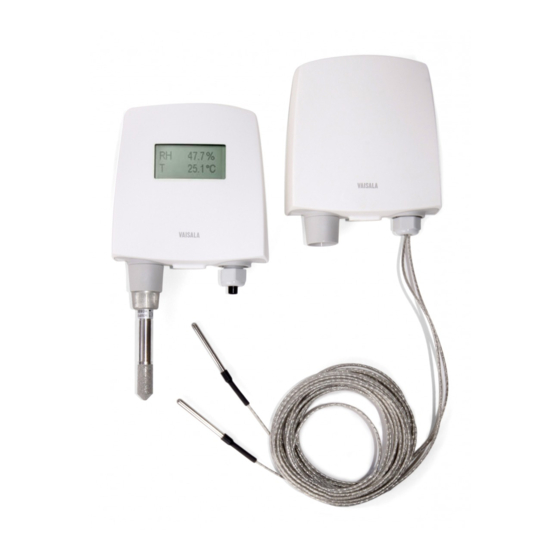
HMT140 Components Figure 1 illustrates the main features of the HMT140. On the left is a remote probe model without display, and on the right is a fixed probe model with the optional display. The numbers and arrows indicate the main components of the HMT140 models. -
Page 15: Installation Kit
Template, available inside the back cover of the Quick Guide. HMT140 Utility and Configuration Cable To connect an HMT140 to your network, you will need to install the HMT140 Utility software and connect the HMT140 to your PC with the configuration cable (see, Connecting to your Network, on page 24). - Page 16 Introduction to the HMT140 VAISALA...
-
Page 17: Chapter 3 Installation
CHAPTER 3 INSTALLATION This chapter provides the information you need to: • Mount the HMT140 on a wall or duct • Connect the HMT140 to your network • Review optional mounting accessories M211488EN-E... -
Page 18: Mounting
HMT140 to ensure an uninter- rupted radio signal. Open the HMT140 cover. Use your thumb to press and hold the release tab located between the two glands (see Figure 9 on page 19), then pull the cover out and up with your other hand. -
Page 19: Duct Installation
Figure 2: Mounting Diagram It is strongly recommended that you use all four Note: screws; however, the HMT140 enclosure fasten- ing holes are initially covered with a thin plastic membrane, so less than four screws could be also be used without sacrificing the ingress protection (IP) class of the enclosure. - Page 20 Figure 3: Probe Installation The following numbers refer to Figure 3: Tension screw Distance L can be adjusted and locked in place with the tension screw. Probe Assembly with Duct Installation Kit Figure 4: Probe Assembly with Duct Installation Kit VAISALA...
- Page 21 Mounting The following numbers refer to Figure 4: Probe (HMP110D) Duct installation kit Probe cable To assemble the probe: Pass the probe cable through the plastic pipe of the duct installation kit. Connect the probe cable to the HMP110D. Figure 5: Drilling Instructions The following numbers refer to Figure 5: Mounting screw Tension screw...
-
Page 22: Optional Mounting Accessories
Figure 6: Drilling specifications Optional Mounting Accessories Probe Mounting Flange The probe mounting flange (Vaisala order code: 226061) is a general purpose mounting flange for 12 mm diameter probes. It can be used to hold the HMP110D probe in a through-wall installation. -
Page 23: Wiring Diagrams
HMT140 (not the HMT141). Wiring Diagrams The following figures outline the components, wiring and connections of the HMT140. - Page 24 Wiring Diagrams Figure 10: RTD Wiring Diagram Figure 11: RTD and Boolean Wiring Diagram Figure 12: Boolean Wiring Diagram VAISALA...
- Page 25 Wiring Diagrams Figure 13: Voltage Wiring Diagram Figure 14: Current Wiring Diagram Figure 15: Power Supply Wiring Diagram M211488EN-E...
- Page 26 Wiring Diagrams M211488EN-E...
-
Page 27: Chapter 4 Setup And Operation
CHAPTER 4 SETUP AND OPERATION This chapter will guide you during the setup of your HMT140 with your network parameters. Here you will find the information you need to: • Configure the HMT140 • Operate the HMT140 • Customize the HMT140 for your network... -
Page 28: Connecting To Your Network
Configuration Cable to a USB port on your PC to complete the installation. You are now ready to set up and configure your HMT140. If you wish to remove the HMT140 Utility software at a later date, use the uninstall function on your Windows Control Panel. -
Page 29: Set Up The Hmt140
Pry the case open with a slot screwdriver if you are unable to open the case by hand. Ensure the power switch on the HMT140 is in the OFF position. The ON/OFF switch only applies to battery Note: power. - Page 30 Connecting to your Network Turn on the HMT140 and wait five seconds to ensure the startup process completes. Plug the USB connector on the HMT140 Configuration Cable to the computer, if it is not already connected. From the start menu, open the HMT140 Utility.
- Page 31 Connecting to your Network The status bar is located at the bottom of the HMT140 Utility window. It contains the following panels: • Left panel: Displays the Configuration Cable status: Found USB Programmer or Looking for USB Programmer. • Middle panel: Displays progress messages of the different actions: Update, Retrieve, Status, and Info.
-
Page 32: Custom Settings
To modify transmission settings: Ensure the HMT140 case is open and the correct batteries are installed. (Vaisala part#: 236318SP). Turn on the HMT140 and wait five seconds to ensure the startup process completes. Plug the USB connector on the HMT140 Configuration Cable to the computer, if it is not already connected. - Page 33 Custom Settings For example, if you select 15 minutes for the Transmit Period, and 3 for the number of Tries, the HMT140 will attempt to transmit every 15 minutes. If it cannot trans- mit, it will make 3 transmission attempts, then will go into ‘sleep’...
- Page 34 Enable Proximity Attention Sensor: to enable or disable the proximity attention sensor. The sensor is used to wake up the HMT140 and to cause the HMT140 to send a data packet to the host. Select the length of time the display...
-
Page 35: Modify Hmt140 Description
Optional: Enter a name for the saved settings on the Set up tab in the Saved Settings field and click the disk icon to save. If the HMT140 is used with more than one wireless network, enter a name in the Saved Net- work Settings field and click Save. - Page 36 – IP settings are successfully assigned and the Cache HMT140 will cache this IP address • – the HMT140 could not obtain the IP settings. Failed Current IP address. If “0.0.0.0”, then no IP IP Address: address has been assigned.
-
Page 37: Hmt140 Function Modes
This is the channel found during the Channel Channel: Auto Find feature or the channel set in the Setup page. If the HMT140 cannot find a channel when in Auto Find mode, the utility will display “none”. Check HMT140 battery status: Estimated percentage remaining of the battery. -
Page 38: Transmission Of Data
Configuration Cable is not plugged into it, data is transmitted according to the transmit settings. In Transmitter mode, the HMT140 spends most of its time in a very low power state (sleep). When a transmit period is due, it powers up the radio, attempts to link to the specified wireless network, transmits its data and then goes back to sleep. -
Page 39: Alarm-Triggered Transmission
Additional Settings Alarm-triggered Transmission The HMT140 has the ability to initiate a Transmit Attempt based on an alarm, if this functionality is configured in viewLinc. An alarm can be triggered either when the measured value exceeds a high threshold or goes below a low threshold for a period of time, as configured in viewLinc. -
Page 40: Save And Recall Settings
Delete Network Setup, then choose the correct set- tings name to delete. Restart the HMT140 You may want to reboot your HMT140 to reconnect to the network and re-acquire status information. On the Status tab, click Restart. Get General Information To gather general information about the HMT140, select the Info tab and then click Get. -
Page 41: Battery Usage
Battery Usage Battery Usage The HMT140 has a built-in battery meter. This meter is based on a count of its transmissions. To determine battery life remaining, the meter records the amount of power used during transmission relative to the power remaining. -
Page 42: Units And Temperature
On the Options tab, select Units. Connection Performance Consistent connection performance is essential for longevity of battery life. The HMT140 Utility can perform a test to indicate how well the HMT140 connects to the network, which provides an indication about the expected battery life. -
Page 43: Advanced Options
If the average connection time is too long it is important to try isolate the cause. To isolate a connection problem: Open the HMT140 Utility and connect the Configuration Cable to the HMT140 and your PC. Temporarily turn off one of the connection options and then measure the average connection time: •... - Page 44 When this option is selected, the Log Conversations: HMT140 Utility will capture the conversation between the utility and the HMT140 and place it in a file called OutputLog.txt. To locate the file, go to the Help menu, select Utility Folder Paths, and then Explore Data.
-
Page 45: Passwords
To improve security, you can require that a user log in to make changes to HMT140 parameters. If Passwords are enabled, a password prompt appears when a user clicks Update on the Setup tab. No other HMT140 functions will require a login password. To set, change or remove an HMT140 password: Open the HMT140 Utility. -
Page 46: Set Up A New Channel
Set Up a New Channel On the Network tab, you can select a specific Channel to view, using the Channel field. To select multiple Channels for the HMT140 to search when connecting to an access point or a wireless router, select Auto Find. -
Page 47: Test Network Connectivity
Ping from Sensor When the Ping From Sensor button is clicked, the HMT140 will use either the IP address in the IP Address field or the current address in the Destination IP field in the Setup tab and ping that specified address. Once the ping operation is complete, the utility will either indicated failed or success and specify the IP address in the Result field. -
Page 48: Additional Program Parameters
Additional Program Parameters Contact Destination Host The HMT140 Utility will instruct the HMT140 to send a transmission (data packet) to the Destination Address. If the Destination responds with an acknowledgement, the Utility will indicate success, otherwise the Utility will display “Failed”... -
Page 49: Chapter 5 Maintenance
CHAPTER 5 MAINTENANCE This chapter provides information to help you provide basic in- house maintenance of the HMT140, including: • Instructions for replacing the HUMICAP RH sensor ® • Instructions for removing and fastening probes • Calibration and adjustment information •... -
Page 50: Replacing The Humicap® Rh Sensor
To remove and replace a fixed probe: Loosen the metal locking bushing by carefully turning it counter clockwise. Remove the probe from the HMT140 by pulling it gently outwards. Attach the new probe to the 4-pin M8 panel connector on the HMT140 (only one position possible). -
Page 51: Remote Probe Model
Removing and Fastening the Probe The following numbers refer to Figure 16: Locking bushing Holder bushing (attached permanently to the probe) HMP110D probe Remote Probe Model To remove and replace a remote probe: Unscrew the small sleeve at the end of the probe cable that secures the probe in place, and pull out the probe. -
Page 52: Calibration And Adjustment
To replace the batteries and reset the battery meter of the HMT140: Open the HMT140 case. Use your thumb to press and hold the release tab, located between the two glands, then pull the cover out and up with your fingers. See HMT140 Components Diagram on page 19 for location of release tab. -
Page 53: Appendix
APPENDIX SPECIFICATIONS AND TROUBLESHOOTING Specifications Table 1: Humicap Relative Humidity Measurement Specifications (with HMP110D) Property Description/Value Measurement range 0 ... 100% RH Accuracy (including non-linearity, hystere- sis, and repeatability): at 0 ... +40 °C (+32 ... +104 °F) ± 1.7 %RH (0 ...90 %RH) ±... - Page 54 -196 °C to +90 °C RTD Accuracy over temperature range ° -196 to -90 +/- 2.5 ° -90 to -30 +/- 0.75 ° -30 to 0 +/- 0.5 ° 0 to 50 +/- 0.25 ° 50 to 90 +/- 0.75 VAISALA...
- Page 55 Table 4: Humicap Operating Environment Specifications Property Description / Value Operating temperature range HMT140 device body, no display -40 ... +60 °C (-40 ... +140 °F) HMT140 device body, with display -20 ... +60 °C (-4 ... +140 °F) HMP110D probe -40 ...
- Page 56 Appendix Specifications and Troubleshooting HMT140 Dimensions (Fixed Probe) VAISALA...
-
Page 57: Hmt140 Dimensions (Remote Probe)
HMT140 Dimensions (Remote Probe) M211488EN-E... -
Page 58: Hmt140 Dimensions (Fixed Probe)
Appendix Specifications and Troubleshooting Table 5: Mechanics Specifications Property Description / Value Operating Temperature Range HMT140 device body, no display -40 C ... +60 °C HMT140 device body, with display -20 C ... +60 °C Material HMT140 device housing PBT plastic... - Page 59 Table 6: Wireless Specifications Property Description / Value Modulation 802.11b compatibility: DSSS(CCK-11, CCK-5.5, DQPSK-2, DBPSK-1) 802.11g:OFDM (default) Channel intervals 5MHz Channels 1-14 Wi-Fi Security WEP (128-bit), WPA, WPA2 (Personal) Output Power +18dBm (63mW) Receiver Sensitivity -85dBm (63mW) Antenna Onboard Whip Data Rates 802.11b: 1,2,5.5,11 Mbps 802.11g: 6,9,12,18,24,36,48,54 Mbps...
-
Page 60: Troubleshooting
The HMT140 is in Transmitter mode when the Configuration Cable is not connected, and the HMT140 power switch is turned on. When in Transmitter mode, the HMT140 remains in a low power state, but will turn on, connect, transmit a UDP packet, and then go back to the low power state when it is ready to transmit. - Page 61 Is the connect time too long? If the connect time to the network is consistently long (over five seconds), the HMT140 may not be able to connect to the network. If you suspect the connect time to the network is...
-
Page 62: Hmt140 Operation Mode
Use the Ping from PC function in the HMT140 Utility (if this PC is connected) and see if you can ping the HMT140 when it is in Config mode. Go to the Status tab to determine the IP address. VAISALA... - Page 63 Sensor function in the Utility to have the HMT140 ping the host. Use the Ping from PC feature if this PC is connected or a PC on the network and ping the host. Also try pinging the HMT140 when it is in Config mode. Check the following: •...
- Page 64 Appendix Specifications and Troubleshooting Check if the hostname is being resolved in Config mode (go to the HMT140 Utility Status tab and examine the Resolved Destination field). Can connect to the network and Contact Destination using the utility, but host is not receiving UDP packets in Transmitter mode.
- Page 65 Make sure the HMT140 Configuration Cable is connected to the HMT140. Disconnect the cable, power the HMT140 off, power back on, wait 5 seconds, connect the cable and try again. • Does the red LED in the programming cable flash when...
- Page 66 Workaround: Use Dynamic IP and have DCHP Caching turned off. If the IP address is static or the DHCP Caching is enabled, these routers will not forward the HMT140’s UDP data packet. Replace the router (contact Vaisala Technical Support). VAISALA...
- Page 67 Channels deleting settings Auto Find Fixed Probe Model checking battery life getting information components models Config (setup) mode modes configuration cable mounting connecting optional display HMT140 to your network overview HMT140 to your PC Remote Probe Model connection performance M211488EN-E...
- Page 68 HMT140 components power supply wiring HMT140 Components diagram probe HMT140 Configuration Cable removing/fastening 46, 47 HMT140 connecting to network Probe Assembly with Duct Installa- HMT140 Utility tion Kit HMT140Utility.INI file Probe Mounting Clamp HUMICAP® Sensor replacing recording passwords...
-
Page 69: Index
Index transmission of data transmit attempts Transmitter mode transmitter type, viewing USB cable viewing calibration status transmitter type Voltage Wiring Diagram wall mounting wiring boolean diagram current diagram power supply diagram RTD and Boolean diagrams RTD diagram voltage diagram M211488EN-E... - Page 70 *M211488EN*...
Need help?
Do you have a question about the HMT140 and is the answer not in the manual?
Questions and answers