Table of Contents
Advertisement
Quick Links
Advertisement
Table of Contents

Related Manuals for TVLogic R-5T


Summary of Contents for TVLogic R-5T
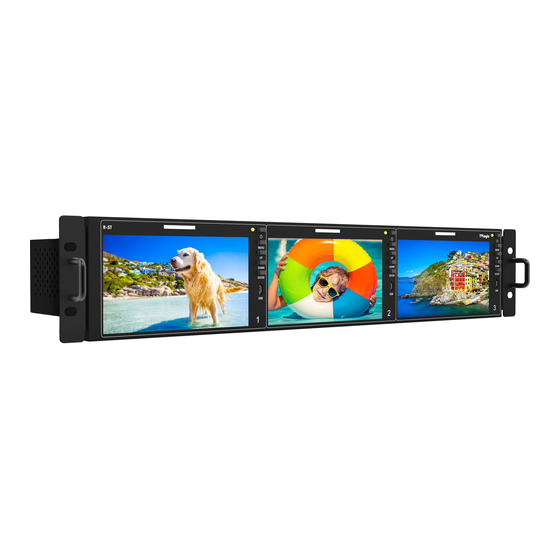
- Page 1 LCD Rack Mountable Monitor R-5T...
-
Page 3: Table Of Contents
Contents ..................1. Caution ................2. Main Features ..............3. Controls & Functions ............... 4. Menu Tree & Adjustment ................5. Menu Operations ..................[1] Picture ..................[2] Color ..................[3] Marker ................. [4] Display / Video ................[5] Waveform .................. -
Page 4: Caution
1. Caution Always use set voltage. • • Do not overload DC outlets or extension cords. (DC 12V MAX 6A) Overloading can cause or electric shock. When using outdoors, use the product • Never insert an object into the product through •... - Page 5 1. Caution • When mounting the product on a wall or ceiling, • Sudden stops, excessive force and uneven be sure to install the product according to the floor surface can cause the product to fall from method recommended by the manufacturer. the cart.
-
Page 6: Main Features
2. Main Features R-Series Monitors contain the following features : • Compatible with various SDI signals • Power formats (SD/HD/3G/12G) - Basically, this product is powered by a normal DC source. - This product is compatible with various SDI - The product can be battery-powered. signals - 480i, 576i, 720p, 1080i, 1080p, 1080psf * DC 6~12V (Typical) •... -
Page 7: Controls & Functions
• [TALLY] • [USB] - Tally lamp that can be toggled in green or red - Use the Micro B Type USB. The OTG gender using the REMOTE(RS-422) port or TVLogic’s is required when using a USB Memory control program(Observer). Stick. - Page 8 3. Controls & Functions REAR 12G/6G/3G 12G/6G/3G 3G-SDI 3G-SDI SDI IN SDI OUT HDMI RS-422 IN RS-422 OUT REMOTE DC IN • 12G/6G/3G [SDI IN/OUT] (BNC) • DC IN - Signal input/output terminals for 12G/6G/3G/ -12V DC HD/SD SDI signal. - Outputs the SDI signal input from the [SDI IN] <WARNING!!>...
-
Page 9: Menu Tree & Adjustment
1. Press the MENU button to activate the OSD R-Series. menu. 2. Move to a desired menu with the UP/DOWN PICTURE 같이 R-5T button. BRIGHT 3. Press the ENTER button to select a menu and CONTRAST CHROMA move to a sub-menu with the UP/DOWN SHARPNESS button. -
Page 10: Menu Operations
5. Menu Operations [1] PICTURE • 3DLUT LOAD PICTURE 같이 R-5T - Used to apply the internally stored 3DLUT. BRIGHT - Maximum 3 x 3DLUT files can be stored. CONTRAST CHROMA - The file name can be set up to 20 characters SHARPNESS including the extension. -
Page 11: Color
COLOR GAMUT BT.2020 For example, the lowest luminance that the COLOR TEMP 6500K R-5T can display is 0.002, but it is necessary EOTF LOCAL DIMMING to adjust the offset level to about 0.2nit when EETF using under bright light. At this time, when the HLG SG black level is set to 0.2, dark gradations below... - Page 12 5. Menu Operations [2] COLOR • SG (System Gamma) COLOR같이 R-5T - The System Gamma of HLG is automatically STANDARD calculated and displayed according to the set VIDEO RANGE LIMITED109 PEAK LUMINANCE peak luminance. BLACK LEVEL 0.001 - Activates only when the EOTF is set to HLG and COLOR GAMUT BT.2020...
- Page 13 5. Menu Operations [2] COLOR • COLOR SPACE COLOR같이 R-5T - Used to select the standard color space. COLOR TEMP 6500K - Available options are BT.709, DCI-P3, BT.2020 GAIN RED GAIN GREEN and Native. GAIN BLUE BIAS RED BIAS GREEN...
-
Page 14: Marker
5. Menu Operations [3] MARKER • FIT MARKER MARKER같이 R-5T - Used to activate or inactivate the Fit Marker ENABLE function. MARKER CENTER MARKER - When the Marker type is selected in the Marker SAFETY AREA menu, a border line of the Safety Area will be FIT MARKER displayed inside the Marker.Images below... - Page 15 5. Menu Operations [3] MARKER • GRID ENABLE MARKER같이 R-5T - Used to activate the GRID display function. ENABLE MARKER • GRID TYPE CENTER MARKER - Used to select the GRID type. SAFETY AREA FIT MARKER - Available GRID types are 3x3, 4x4, 5x5 and 6x6.
-
Page 16: Display / Video
5. Menu Operations [4] DISPLAY / VIDEO • BLUE ONLY DISPLAY / VIDEO이 R-5T - Used to switch in the order of [Off]-[Blue Only]- SCAN ZERO SCAN [Mono]-[Off]. ASPECT 16:9 H/V DELAY - Press the button to remove red and green... - Page 17 5. Menu Operations [4] DISPLAY / VIDEO • FOCUS ASSIST DISPLAY / VIDEO이 R-5T - Focus Assist helps the shooters to easily find DSLR CANON 7D out the exact area in the picture with good DSLR SCALE LIVE VIEW TIMECODE...
- Page 18 5. Menu Operations [4] DISPLAY / VIDEO DISPLAY / VIDEO이 R-5T DSLR CANON 7D DSLR SCALE LIVE VIEW TIMECODE FOCUS ASSIST FOCUS AS COLOR FOCUS AS LEVEL + 90 ARRI CAM STATUS LD INFO INDEX LETTER PAGE(2/2) • ARRI CAM STATUS - Used to set the Status Information provided by the ARRI ALEXA Camera.
-
Page 19: Waveform
5. Menu Operations [5] WAVEFORM • SIZE WAVEFORM R-5T - Adjust the size of the Waveform or Vectorscope. ENABLE - Can select among [NORMAL] and [LARGE]. TYPE INTENSITY + 90 * See section “7. Other Function [2] Waveform/ TRANS OPAQUE Vectorscope”... - Page 20 5. Menu Operations [5] WAVEFORM • RANGE ERROR WAVEFORM R-5T - Used to set whether or not to activate Y MAX, ENABLE Y MIN, C MAX, C MIN, Y PICTURE BLINK and C TYPE INTENSITY + 90 PICTURE BLINK functions.
- Page 21 5. Menu Operations [5] WAVEFORM Y PICTURE BLINK • WAVEFORM R-5T - Used to set whether or not to blink pixels with ENABLE values exceeding Y MAX and Y MIN. TYPE INTENSITY + 90 TRANS OPAQUE C PICTURE BLINK •...
-
Page 22: Audio
5. Menu Operations [6] AUDIO • LVM SIZE AUDIO R-5T - Used to control the size of the audio level LEVEL METER meters. LVM DISPLAY PAIR LVM REFERENCE -18dB - Available options are NORMAL and LAGRE. LVM SIZE SMALL PEAK DECAY TIME + 90 •... -
Page 23: System / Gpi / Umd
5. Menu Operations [7] SYSTEM / GPI / UMD • ECO SAVING SYSTEM / GPI / UMD R-5T - Used to save power consumption DEFAULT automatically when there is no monitor signal. LUMINANCE + 48 INTERNAL PAT - When the signal is supplied, the brightness of DISPLAY ENABLE the monitor will be changed to the set value. - Page 24 5. Menu Operations [7] SYSTEM / GPI / UMD SYSTEM / GPI / UMD R-5T REMOTE (RJ-45) GROUP ID MONITOR ID 1: Pin1 RS-422 BAUD 2: Pin2 PIN 1 NONE PIN 2 NONE 3: Pin3 PIN 3 NONE 4: Pin4...
- Page 25 5. Menu Operations [7] SYSTEM / GPI / UMD • UMD CHARACTER SYSTEM / GPI / UMD R-5T - Used to customize the characters for Under UMD ID Monitor Display. UMD DISPLAY UMD CHARACTER CHANNEL 1 ▼ - Press the [ENTER] button to activate the Virtual...
- Page 26 5. Menu Operations [7] SYSTEM / GPI / UMD • TALLY COLOR SYSTEM / GPI / UMD R-5T - Used to set the color of each Tally 1, Tally 2, UMD ID Tally 3 and Tally 4. UMD DISPLAY UMD CHARACTER CHANNEL 1 ▼...
- Page 27 5. Menu Operations [7] SYSTEM / GPI / UMD <Dynamic UMD Protocol (TSL V3.1)> * Transmission (18 Byte) (PC or Device -> Monitor) HEADER CONTROL DISPLAY DATA (1 BYTE) BYTE(1 BYTE) (16 BYTE) * [HEADER] : Display address (0~126) + 80 hex. * [CONTROL BYTE] bit 0 : Tally 1 (1=on, 0=off) bit 1 : Tally 2 (1=on, 0=off)
- Page 28 5. Menu Operations [7] SYSTEM / GPI / UMD Tally Type - Default ● - S-8C(Single 8 Character) & S-16C(Single 16 Character) Bit 1 Bit 1 Operation (Tally2) (Tally1) CHANNEL1 CHANNEL1 CHANNEL1 CHANNEL1 - D-8C(Dual 8 Character) Bit 1 Bit 1 Operation (Tally4) (Tally3)
-
Page 29: Button Functions
6. Button Functions [1] Input Button SDI A SDI B HDMI NO VIDEO • The R-Series monitors support the various input signals. 1. Press the [MENU] button on the front of the monitor for more than 2 seconds and activate the OSD menu as shown on the left. -
Page 30: Other Functions
7. Other Functions [1] User Aspect • Used to adjust the Width /Height display USER ASPECT ratio. WIDTH +1920 1. Select [Aspect] mode in the OSD menu by HEIGHT +1080 pressing the function button on the right top of the monitor to activate the [USER ASPECT] mode. - Page 31 7. Other Functions [2] Waveform / Vectorscope • Waveform Y • VectorScope - Displays the Luma(Y’) component of the input - Displays the color components ‘B-Y’ and ‘R-Y’ signal into waveform. of the input signals onto the X-Y axis. - Two different types of Vetorscopes are displayed according to SD or HD input signals.
- Page 32 7. Other Functions [3] Line Select (Waveform/VectorScope) [4] Zoom • Used to select specific Vertical Line for • Used to magnify the input signal from 0% WaveForm/VectorScope. to 90%. - This is available when LINE WaveForm is - Supports Zoom Width Scroll / Zoom Height activated.
- Page 33 7. Other Functions [5] Luma(Y’) Zone Check • Color Pattern Type • Zebra Pattern Type - Displays the pixels with designated Luma(Y’) - Displays the Luma(Y’) level of the input image levels with zebra pattern. in colors. - Y’ ≥ 100%: Pixels with Y’ level over 100% turn - Y’...
- Page 34 7. Other Functions [6] Focus Assist [7] Range Error • Pixels with Y’ or C’ levels exceeding the • Focus Assist function assigns a color to the pixels in the shape or the boundary of the designated levels of Y MAX, Y MIN, C MAX and C MIN shall blink.
- Page 35 7. Other Functions [8] DSLR Scale • This function is designed for some DSLR cameras of Canon(7D) that output different resolution from the operation mode (StandBy, Record, Play Back) • Select the Camera model in the [Display/ Vide]- [DSLR Camera Sel.] menu. •...
- Page 36 7. Other Functions [9] Internal Pattern [10] Arro Cam Status • • Used to display the camera status Displays internally generated test patterns. information provided by ARRI ALEXA - The pattern consists of ColorBar and Pluge+ camera on the OSD. Grayscale Patterns.
- Page 37 7. Other Functions [11] Firmware Upgrade • The USB(Thumb drive) which contains the F/W file is needed for Firmware Upgrade. • Select the SW UPGRADE in the SYSTEM menu. 1. Connect the USB to the USB Slot on the front of the monitor. 2.
- Page 38 9. Video Support Resolution VIDEO Support Resolution Input Signal Signal Foramt (SD SDI) Interfaces SD SDI 720x487(59.94i) YCbCr 4:2:2 10bit single link 720x576 (50i) Input Signal Signal Format (HD SDI) Interfaces 1920x720 (50/59.94/60P) HD-SDI YCbCr 4:2:2 10bit 1920x1080 single link (23.98/24/25/29.97/30p) (50/59.94/60i) (24/25/29.97/30psf)
-
Page 39: Video Support Resolution
9. Video Support Resolution VIDEO Support Resolution Input Signal Signal Format (12G SDI) Interfaces 12G-SDI 4096/3840x2160 (60/59.94/50p) 12G-SDI (A) YCbCr 4:2:2 12bit single link 6G-SDI 4096/3840x2160 (30/29.97/25/24/23.98p) Input Signal Signal Format (HDMI) Interfaces 1080p (60/59.94/50/30/29.97/25/24/23.98) 1080i/60/59.94/50) RGB 4:4:4 8bit / 10bit / 12bit HD SDI 720p (50/59.94/60p) YCbCr 4:4:4 8bit / 10bit / 12bit... -
Page 40: Product Specifications
10. Product Specifications R-5T Size 5.5” Resolution 1920×1080(16:9) Pixel Pitch 0.0213(W) x 0.0639(H) mm Color Depth 16.7M (True) Viewing Angle H : 160 degrees / V : 160 degrees Luminance of white 500 cd/ m (Center) Contrast Ratio 1,000 : 1 Display Area 122.7(H)x69.0(V) mm... - Page 41 MEMO...
- Page 42 MEMO...
- Page 44 FOR MORE INFORMATION PLEASE VISIT : http://www.tvlogic.tv 12F, ACE HIGH-END 8, 345-4 Gasan-dong, Geumcheon-gu, Seoul, 18590, KOREA 부사장 TEL : +82-70-8668-6611, FAX : 82-2-6123-3201, E-mail : sales@ t vlogic.co.kr 조 성 일 153-802 서울특별시 금천구 가산동 345-4 에이스하이엔드 8차 12층...
Need help?
Do you have a question about the R-5T and is the answer not in the manual?
Questions and answers