Advertisement
Advertisement

Related Manuals for TVLogic LVM-240W


Summary of Contents for TVLogic LVM-240W
- Page 1 CEV.FR Multi User’s Manual Multi-Format LCD Monitors LVM Series LVM-240W...
-
Page 2: Table Of Contents
Contents Warnings ................... 2 Features .................... 3 Name & Function of Each Part ............4 Menu Organization & Adjustment ............ 9 Menu Contents ................11 Other Functions ................14 FCC (Federal Communications Commission) This equipment has been tested and found to comply with the limits for class A digital device, pursuant to part 15 of the FCC Rules. -
Page 3: Warnings
Warning · Always use set voltage. - AC 100 ~ 240V (1.8A/50~60Hz) - DC 24V · If liquid is spilled on or impacts this product, please disconnect the product immediately and seek professional help before continued use. · Keep unit disconnected during extended periods of disuse. ·... -
Page 4: Features
Features LVM Series units have the following features: Compatible with varied SDI signals The product is compatible with varied SDI Signals - 480i, 576i, 720p, 1080i, 1080p, 1080psF (SDI A, B 2 channel compatible) Compatible with varied analog signals The product is compatible with varied analog signals - Composite, S-Video, Component, RGB, etc. -
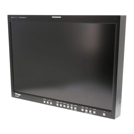
Page 5: Name & Function Of Each Part
Name & Function of Each Part <FRONT> TALLY ANALOG INPUT STAND BY SDI INPUT SELECT ENTER UNDER SCAN UP / CONTRAST ASPECT DOWN / BRIGHT MARKER MENU H/V DELAY CHROMA/PHASE BLUE ONLY / MONO <REAR> REMOTE VGA IN / FACTORY PGM CVBS1 / Y / G / S-Y CVBS2 / Pb / B CVBS3 / Pr / R / S-C... - Page 6 <FRONT> · ANALOG INPUT Used to select desired ANALOG INPUT. A Sub Menu for each analog input connected can be selected. · SDI INPUT SELECT Used to select SDI INPUT A or B. · UNDER SCAN Used to transfer from OVER SCAN mode to UNDER SCAN mode. (Compatible up to SD 1:1 SCAN mode.) ·...
- Page 7 · MENU Used when OSD menu is activated. · DOWN/BRIGHT Used to navigate menu during OSD menu activation. It may also be used to control the BRIGHT value when the OSD menu is not active. · UP/CONTRAST Used to navigate the menu during OSD menu activation. It may also be used to control the CONTRAST value when the OSD menu is not active.
- Page 8 <REAR> · REMOTE (RJ-45) Connection for remote control of monitor. · VGA IN / FACTORY PGM Input connection for VGA mode and input connector for FACTORY PGM allowing for firmware updates. · CVBS1/Y/G/S-Y (BNC) Signal input terminal used for COMPOSITE1, S-VIDEO Y, COMPONENT Y, RGB G signals. ·...
- Page 9 Information Input VIDEO connection method Connector Composite Component S-Video CVBS1 CVBS2 No Con. CVBS3 Warning!! Before using this unit make certain to connect the power supply before connecting a signal to any of the inputs. The unit may not function properly if a signal is connected before the power supply is connected.
-
Page 10: Menu Organization & Adjustment
Menu Organization & Adjustment The product may be controlled and set system-wide through an OSD. 1) Menu Organization Below is the organization of the product’s menu. 2) Menu Control You may control various functions using MENU, UP/DOWN and ENTER buttons on the bottom-front of the monitor. - Page 11 3. Press ENTER to select an item, make sure the item turns red and then change the set value. 4. Select the desired new value with the UP/DOWN button. 5. Press ENTER to save the new value (verified by highlighted field returning to default black color).
-
Page 12: Menu Contents
Menu Contents Below is the description of each function of the menu. · BRIGHT This item controls the degree of brightness between MAX(50) and MIN (-50) range. · CONTRAST This item controls the contrast ratio between MAX(50) and MIN(-50). · COLOR This item controls COLOR TEMP . - Page 13 Compatible MARKER types are as follows: MODE MARKER CLASS 4:3, 4:3 ON AIR 15:9,14:9,13:9 1.85:1, 2.35:1 SD 16:9 1.85:1 & 4:3 SD 4:3 16:9 · CENTER MARKER This item displays the CENTER MARKER on the screen. This function operates only after activating the MARKER function by pressing the MARKER button on the front of the monitor.
- Page 14 · REMOTE SETUP This product is compatible with exterior REMOTE CONTROL. The user may access the remote setup menu from here. · SYSTEM You can use the SYSTEM menu to confirm the hours of use on the product or additional product information. ·...
-
Page 15: Other Functions
Other Functions 1) ANALOG Mode Usage This product is capable of processing all input signals usable in ANALOG mode. The ANALOG input settings are as follows: 1. Press ANALOG button on the front of the product and activate the menu below. 2. - Page 16 2. Select COLOR among MENU and you will see below OSD MENU. 3. On COLOR TEMP item, Press ENTER and select one of 5000K, 5600K, 6500K, 9300K and USER using UP/DOWN button and press ENTER. If you selected USER mode, you can set the value RED, GREEN, BLUE GAIN and BIAS.
- Page 17 5. COLOR COPY mode can be used only in USER MODE. If user wants to change only a specific value from standard mode, it will be a useful function. If the color temp. is 6500K, and user wants to change only the blue gain value, the user can COLOR COPY function as following steps;...
- Page 18 The user may designate functions for PIN1 ~ PIN 6. PIN7 is for POWER ON/OFF use only. The selectable functions are as follows: Menu Classification Settable Values NONE, ANALOG CHANNEL DIGITAL A,B CHANNEL TALLY R,G , BLUE ONLY SD 1:1 SCAN, UNDER SCAN ASPECT, H/V DELAY 16:9,15:9,14:9,13:9 MARKER PIN 1~6...
- Page 19 4) SD 1:1 SCAN Mode Widescreen models provide not only an UNDER SCAN mode but also an SD 1:1 SCAN mode. These modes may be selected as follows: 1. Transfer to UNDER SCAN by pressing the UNDER SCAN button on the front of the monitor.
- Page 20 · DOT PHASE Use this item for tuning the screen. Controls DOT PHASE value between MAX(31) and MIN(0). · H SHIFT Use this item to move the entire screen to the left or right. Controls H SHIFT value between MAX(63) and MIN(-64). ·...
- Page 21 6) DVI-DIG Mode DVI_DIG mode is separated into Graphic mode and Video mode. Graphic mode supports the below resolutions and frequencies. Resolution Frequency 640 × 480 60Hz, 75Hz, 85Hz 800 × 600 60Hz, 72Hz, 75Hz, 85Hz 1024 × 768 60Hz, 70Hz, 75Hz, 85Hz 1280 ×...
- Page 22 Video mode supports the following input signals. SMPTE-274M 1080i (60 / 59.94) SMPTE-296M 720p (60 / 59.94) SMPTE-125M 480i (59.94), 480p(59.94)
-
Page 23: Product Specification
Product Specification Below is the product specification Above specifications may be changed without notice. -
Page 24: Product Lineup
Product Lineup · LCD Resolution - 800 × 480 (15:9) · Color - 262K, 18bit · Contrast - 300:1 · Viewing Angle - 130˚ LVM - 070W · Weight - 1.4Kg 7 inch Multi-Format Monitor · LCD Resolution - 1024 × 768 (4:3) ·... - Page 25 V-Mount 7” 8.4” 17” Rack-Mountable Kit 7” 8.4” 17” Developed by For more information please visit : www.tvlogic.co.kr World Meridian Venture Center II #610, 426-5 Gasan-Dong , Geumcheon-gu, Seoul, 153-803, Korea TEL : +82-2-2025-8191 FAX : +82-2-2025-8192 E-mail : support@tvlogic.co.kr...
Need help?
Do you have a question about the LVM-240W and is the answer not in the manual?
Questions and answers