
Related Manuals for TVLogic RKM Series


Summary of Contents for TVLogic RKM Series
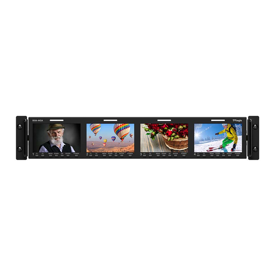
- Page 1 LCD Rack Mountable Monitor RKM-Series RKM-535A RKM-443A RKM-356A RKM-270A RKM-290A...
-
Page 3: Table Of Contents
Contents 1. Caution 2. Main Features 3. Controls & Functions 4. Menu Tree & Adjustment 5. Menu Operations [1] Picture [2] Color [3] Marker [4] REMOTE [5] Waveform [6] Audio [7] Display & Set 6. Button Functions 7. Other Functions 8. -
Page 4: Caution
1. Caution • Always use set voltage. (DC 12V/MAX 6A) • Do not attempt to repair the product yourself. Removing covers can expose you to high voltage and other dangerous conditions. • All operating instructions must be read and Request a qualified service person to perform understood before the product is operated. - Page 5 LCD screen may be stuck to show either always on (red, green, blue) or always off (black or dark). TVLogic guarantees more than 99.999% of the sub-pixels are operating normally and less than 0.001% of the sub-pixels may be defective.
-
Page 6: Main Features
2. Main Features RKM-Series Monitors contain the following features: • Compatible with various SDI signals • 1:1 SCAN/ZOOM - Used to display the original image resolution formats without scaling to match a certain resolution - This product is compatible with various SDI or an aspect ratio. -
Page 7: Controls & Functions
3. Controls & Functions RKM-535A : FRONT TALLY DOWN ENTER MENU POWER /SOURCE • [TALLY] Lamp • [POWER] Button - Tally lamp that can be toggled in green or red - Used to turn the power on and off. If the signal using the REMOTE(RJ-45) port or network. - Page 8 The damage may include signal noise, • [ETHERNET IN/OUT] (RJ-45) malfunction of main board or display panel. - This terminal is used to control TVLogic And the connected devices such as camera Monitor control program (Observer). or video source player may also be influenced through signal cable.
- Page 9 3. Controls & Functions RKM-443A : FRONT TALLY F2 MENU DOWN UP ENTER POWER /SOURCE • [TALLY] Lamp • [POWER] Button - Tally lamp that can be toggled in green or red - Used to turn the power on and off. If the signal using the REMOTE(RJ-45) port or network.
- Page 10 TVLogic. power distributor is grounded. • [ETHERNET IN/OUT] (RJ-45) - This terminal is used to control TVLogic Monitor control program (Observer). - Ethernet port for easy firmware updates and remote control(Status Save&Load / LUT Save&Load ).
- Page 11 3. Controls & Functions RKM-356A : FRONT TALLY MENU MONITOR 1 MONITOR 2 DOWN MONITOR 3 ENTER SOURCE POWER • [TALLY] Lamp • [MENU] Button SDI IN-B ETHERNET OUT RS-422 OUT - Tally lamp that can be toggled in green or red - Used to activate the OSD menu of the SDI IN-A HDMI IN...
- Page 12 TVLogic. power distributor is grounded. • [ETHERNET IN/OUT] (RJ-45) - This terminal is used to control TVLogic Monitor control program (Observer). - Ethernet port for easy firmware updates and remote control(Status Save&Load / LUT Save&Load ).
- Page 13 3. Controls & Functions RKM-270A : FRONT TALLY DOWN/UP/ENTER SDI-A/B MENU/EXIT HDMI CVBS SCAN ASPECT MARKER BLUE/MONO POWER HEADPHONE • [TALLY] Lamp • [BLUE]/[MONO] Button/Lamp SDI IN-B ETHERNET OUT RS-422 OUT - Tally lamp that can be toggled in green or red - Activates in the order of [Off]-[Blue Only]- SDI IN-A HDMI IN...
- Page 14 TVLogic. power distributor is grounded. • [ETHERNET IN/OUT] (RJ-45) - This terminal is used to control TVLogic Monitor control program (Observer). - Ethernet port for easy firmware updates and remote control(Status Save&Load / LUT Save&Load ).
- Page 15 3. Controls & Functions RKM-290A : FRONT TALLY HDMI ASPECT BLUE/MONO DOWN/UP/ENTER PHONEJACK CVBS SDI-A SCAN MRKER W-FORM/VECTOR POWER SDI-B MENU/EXIT • [TALLY] Lamp • [SCAN] Button/Lamp - Tally lamp that can be toggled in green or red - Used to change the scan mode. using the REMOTE(RJ-45) port or network.
- Page 16 3. Controls & Functions RKM-290A : FRONT • [BLUE]/[MONO] Button/Lamp • [STANDBY] lamp - Activates in the order of [Off]-[Blue Only]- - Used to indicate the power supply status. [Mono]-[Off] The lamp is RED during power supply and - Press the button to remove red and green GREEN during system is in operation.
- Page 17 (USB Memory stick) or color calibration made by TVLogic. • [ETHERNET IN/OUT] (RJ-45) - This terminal is used to control TVLogic Monitor control program (Observer). - Ethernet port for easy firmware updates and remote control(Status Save&Load / LUT Save&Load ).
-
Page 18: Menu Tree & Adjustment
4. Menu Tree & Adjustment [1] Menu Tree [3] Menu Control Sequence • OSD(On-Screen Display) Menu helps you • Menu Control sequence follows the order use various functions. below: • This Picture is the menu structure for 1. Press the MENU button to activate the OSD RKM-Series. -
Page 19: Menu Operations
5. Menu Operations [1] Picture [2] Color • Brightness • Color Temp. - Used to set the brightness(=offset) level from - Used to select the among preset color -100 to 100. temperatures or adjust the customized color temperature of the monitor. - Preset color temperatures are 5600K, 6500K, • Contrast 9300K and User1/2/3. -
Page 20: Marker
5. Menu Operations [3] Marker • Fit Marker - Used to activate or inactivate the Fit Marker function. - When the Marker type is selected in the Marker menu, a border line of the Safety Area will be displayed inside the Marker. Images below show the difference between Fit Marker On and Off. - Page 21 5. Menu Operations [3] Marker • User Marker H1 - Used to set the position of the first horizontal marker line. - Displayed when Marker menu is set to User. • User Marker H2 - Used to set the position of the second horizontal marker line.
-
Page 22: Remote
5. Menu Operations [4] Remote (Not supported in RKM-535A) - The selectable values are as follows : Menu Classifi- Settable Values cation NONE, CVBS CHANNEL, * HDMI CHANNEL, SDI-A CHANNEL * SDI-B CHANNEL TALLY RED, • This item activates/ deactivates the TALLY GREEN, REMOTE function. - Page 23 - This function adjusts the size of UMD font and • Monitor ID UMD background. - Sets the ID of each monitor for the TVLogic - Available modes are Small and Large. control protocol or DYNAMIC UMD using RS- 422 communication.
- Page 24 5. Menu Operations [4] Remote • D-UMD Tally Type • IP ADDRESS - Tally type configuration setting in D-UMD(D- - Used to set the IP address connected to the 8C), UMD Display. Monitor. - Configuration values are Default, User Color, Character, BG. Color, User Tally, • SUBNET MASK User Char and User BG.
- Page 25 5. Menu Operations [4] Remote <Dynamic UMD Protocol (TSL V3.1)> * Transmission (18 Byte) (PC or Device -> Monitor) HEADER CONTROL DISPLAY DATA (1 BYTE) BYTE(1 BYTE) (16 BYTE) * [HEADER] : Display address (0~126) + 80 hex. * [CONTROL BYTE] bit 0 : Tally 1 (1=on, 0=off) bit 1 : Tally 2 (1=on, 0=off) bit 2 : Tally 3 (1=on, 0=off)
- Page 26 5. Menu Operations [4] Remote • Tally Type - Default - S-8C(Single 8 Character) & S-16C(Single 16 Character) Bit 1 Bit 1 Operation (Tally2) (Tally1) CHANNEL1 CHANNEL1 CHANNEL1 CHANNEL1 - D-8C(Dual 8 Character) Bit 1 Bit 1 Operation (Tally4) (Tally3) CHANNEL1 CHANNEL1 CHANNEL1...
-
Page 27: Waveform
5. Menu Operations [5] Waveform • Waveform Trans. - The item controls the transparency level of the WAVEFORM/VECTOR. - Available values are OPAQUE and TRANS. * If the option is set to OPAQUE, the main OSD will overlap with the waveform/vector. However, it will automatically display it as transparent and goes back to opaque if the main OSD disappears. - Page 28 5. Menu Operations [5] Waveform • Luma(Y’) Zone Check - Displays the Luma(Y’) level of the input image in colors. - May select between [Color Pattern] or [Zebra Pattern]. - Each pixel’s Y’ analized and changed to a certain color or zebra pattern according to the Index on the right side of the screen.
- Page 29 5. Menu Operations [5] Waveform • C Max - Used to set the maximum chroma(C’) level from 0 to 255. - Pixels with values exceeding the min C’ level will blink in the screen, and display in red on the Waveform. • C Min - Used to set the minimum chroma(C’) level from 0 to 255.
-
Page 30: Audio
5. Menu Operations [6] Audio • Level Meter - Used to set the Level Meter for the embedded audio. - Available options are OFF,16 CH(HOR.) and 16 CH(VER.) * 16 CH(HOR.) : Displays 8 channels on top left and 8 channels on top right of the screen horizontally. -
Page 31: Display & Set
5. Menu Operations [7] Display & Set • User Aspect Horizontal - Used to set the Horizontal size of the screen. - Activates only when the SCAN mode is set to USER ASPECT. • User Aspect Vertical - Used to set the Vertical size of the screen. - Activates only when the SCAN mode is set to USER ASPECT. - Page 32 5. Menu Operations [7] Display & Set • Focus Assist Color - Used to select a color for Focus Assist among red, green and blue. - This feature is available only when the Focus Assist mode is activated. • Focus Assist Level - Used to set the edge difference value between the edges in an image.
- Page 33 5. Menu Operations [7] Display & Set • System Default - User can use SET DEFAULT menu to initialize the values of the monitor. • S/W upgrade - Used to upgrade the firmware using USB (Thumb drive). * See section “7. Other Functions -> [9] Firmware Upgrade”...
-
Page 34: Button Functions
6. Button Functions [1] Source Button [2] CVBS Button • RKM-Series monitors support various • RKM-Series monitors support CVBS Input input signal. signal. 1. Press the[SOURCE]] button on the front of 1. Press the [SOURCE] or [CVBS] button on the monitor and activate the OSD menu as the front of the monitor and activate the shown on the below. - Page 35 6. Button Functions [3] HDMI Button [4] SDI Button • RKM-Series monitors Support HDMI • RKM-Series monitors support SDIInput Digital input signal. signal. 1. Press the [SOURCE] or [HDMI] button on 1. Press the [SOURCE] or [SDI] button on the front of the monitor and activate the the front of the monitor and activate the OSD menu as shown on the below.
- Page 36 6. Button Functions [5] Function Key Set Button • Used to make a quick setting of the Function Key. 1. Press the function button(F1~F4) on the front of the monitor for more than 2 seconds and activate the OSD menu as follows. 2.
- Page 37 6. Button Functions [6] SCAN Button • The function can select various scan - 2:1 Scan : Magnifies the original image double and displays it only when the original image mode. size is smaller than a half of the screen size. • Press [SCAN] in front of the monitor and change scan mode.
-
Page 38: Other Functions
7. Other Functions [1] User Aspect • Used to adjust the Width /Height display ratio. 1. Press the [Aspect] button on the front of the monitor to activate the [USER ASPECT] mode. 2. After the activation, press the [ENTER] button to begin controlling. - Page 39 7. Other Functions [2] Waveform / Vectorscope • Waveform Y • Vectorscope - Displays the Luma(Y’) component of the input - Displays the color components ‘B-Y’ and signal into waveform. ‘R-Y’of the input signals onto the X-Y axis. - Two different types of Vetorscopes are displayed according to SD or HD input signals.
- Page 40 7. Other Functions [3] Line Select [4] Zoom (Waveform/Vectorscope) • Used to select specific Vertical Line for • Used to magnify the input signal from 0% Waveform / Vector. to 80%. - It is available when the Line Waveform is • Supports Zoom Width Scroll / Zoom activated.
- Page 41 7. Other Functions [5] Luma(Y’) Zone Check • Color Pattern Type. • Zebra Pattern Type - Displays the Luma(Y’) level of the input image - Displays the pixels with designated Luma(Y’) in colors. levels with zebra pattern. - Y’ ≥ 100% : Pixels with higher Y’ level than 100 - Y’...
- Page 42 7. Other Functions [7] Range Error [6] Focus Assist • Focus Assist function assigns a color to • Pixels with Y’ or C’ levels exceeding the the pixels on the boundaries of the image designated levels of Y MAX, Y MIN, C MAX to inform the user to achieve the and C MIN shall blink.
- Page 43 7. Other Functions [8] Internal Pattern • Displays internally generated test patterns. - The pattern consists of ColorBar and Pluge+Grayscale Patterns. Full screen colors of various gray levels(0~100%) are also embedded. <Color Bar + Pluge Pattern> <Gray Pattern> LCD Rack Mountable Monitor...
- Page 44 * During the update, the monitor screen is off, and nothing functions. * After the update, TVLogic logo shows up on the screen, and the monitor initializes. * Update can take 10~20min. depending on firmware kind.
-
Page 45: Hdmi Support Resolution
8. HDMI Support Resolution HDMI SUPPORT RESOLUTION • HDMI Graphic mode supports the following modes : Resolution Frequency 640 X 480 60Hz, 75Hz 800 X 600 60Hz, 72Hz, 75Hz 1024 X 768 60Hz, 70Hz, 75Hz 1366 X 768 60Hz / 75Hz 1280 X 1024 60Hz / 75Hz 1600 X 1200... -
Page 46: Product Specifications
8. Product Specifications RKM-535A Size 3.54” Resolution 960 x 640 (15:10) Pixel Pitch 0.078(H) x 0.078(V) mm Color Depth 16.7M (True 8bit) Viewing Angle H : 160 degrees / V : 160 degrees Luminance of white 500 cd/ m (Center) Contrast Ratio 1000 : 1 Display Area... - Page 47 8. Product Specifications RKM-443A Size 4.3” Resolution 800 x 480 (15:9) Pixel Pitch 0.117(H) x 0. 117(V) mm Color Depth 16.7M (True 8bit) Viewing Angle H : 160 degrees / V : 160 degrees Luminance of white 600 cd/ m (Center) Contrast Ratio 1000 : 1...
- Page 48 8. Product Specifications RKM-356A Size 5.6” Resolution 1280 x 800 (16:10) Pixel Pitch 0.094(H) x 0. 094(V) mm Color Depth 16.7M (Dithered 8bit) Viewing Angle H : 170 degrees / V : 170 degrees Luminance of white 300 cd/ m (Center) Contrast Ratio 500 : 1...
- Page 49 8. Product Specifications RKM-270A Size 7” Resolution 1024 x 600 (16:9) Pixel Pitch 0.15(H) x 0.15(V) mm Color Depth 16.7M (Dithered 8bit) Viewing Angle H : 170 degrees / V : 170 degrees Luminance of white 400 cd/ m (Center) Contrast Ratio 800 : 1 Display Area...
- Page 50 8. Product Specifications RKM-290A Size 9” Resolution 1920 x 1080 (16:9) Pixel Pitch 0.103(H) x 0.103(V) mm Color Depth 16.7M (Dithered 8bit) Viewing Angle H : 176 degrees / V : 176 degrees Luminance of white 400 cd/ m (Center) Contrast Ratio 800 : 1 Display Area...
- Page 52 FOR MORE INFORMATION PLEASE VISIT : http://www.tvlogic.tv 12F, ACE HIGH-END 8, 84 Gasan digital 1-ro, Geumcheon-gu, Seoul, 18590, KOREA 부사장 TEL : +82-70-8668-6611, FAX : 82-2-6123-3201, E-mail : sales@ t vlogic.co.kr 조 성 일 153-802 서울특별시 금천구 가산동 345-4 에이스하이엔드 8차 12층...
Need help?
Do you have a question about the RKM Series and is the answer not in the manual?
Questions and answers