Table of Contents
Advertisement
Advertisement
Table of Contents

Related Manuals for TVLogic LUM-171G


Summary of Contents for TVLogic LUM-171G
- Page 1 Multi Format 4K LCD Monitor Operation Manual_v1 .3 LUM-171G...
-
Page 3: Table Of Contents
Contents 1. Caution 2. Main Features 3. Controls & Functions 4. Menu Organization & Adjustment 5. Menu Operations [1] PICTURE & VIDEO [2] COLOR [3] GPI / UMD [4] MARKER [5] WAVE & FOCUS [6] AUDIO [7] DISPLAY & SET [8] SIGNAL INFORMATION 6. -
Page 4: Caution
1. Caution Always use set voltage. • • Never insert an object into the product ● AC 100 ~ 240V (1.6A/50~60Hz) through vents or openings. High voltage fl ows ● DC 12V in the product, and inserting an object can ●... - Page 5 1. Caution • • Upon completion of service or repair work, • • When relocating the product placed on a cart, request the service technician to perform safety it must be moved with the utmost care. checks to ensure that the product is in proper Sudden stops, excessive force and uneven fl oor operating condition.
-
Page 6: Main Features
2. Main Features LUM-171G Monitor contains the following features : Compatible with various SDI signal Ethernet & USB support ● ● formats - Supports Ethernet and USB connection for - This product is compatible with various SDI program download, monitor control and signals - 720P, 1080p. -
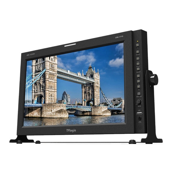
Page 7: Controls & Functions
3. Controls & Functions LUM-171G: FRONT POWER SOURCE SCAN ASPECT MARKER MENU/ EXIT UP/DOWN /ENTER AUDIO OUT LUM-171G : REAR RS-422 OUT RS-422 IN SDI-A~D IN SDI-A~D OUT ~AC IN DC 12V IN HDMI AUDIO-IN REMOTE 4K LCD Monitor 7... - Page 8 3. Controls & Functions FRONT [SOURCE] Button 8). WAVEFORM ● - Used to activate/deactivate various forms of - Used to select an input signal among HDMI, Waveform and Vectorscope. SDI-A, SDI-B, SDI-C, SDI-D, 2SI(2CH), 2SI(4CH), - Waveform only, Vectorscope only, UD MODE(4CH).
- Page 9 3. Controls & Functions FRONT [SCAN] Button [MENU/EXIT] Button ● ● - Used to activate various scan mode (Zero - Used to activate/deactivate the OSD menu. Scan, 2:1 Scan, 1:1 Scan, Fit Width, Over Scan) - Press the MENU button again to deactivate the OSD menu.
- Page 10 3. Controls & Functions LUM-171G : REAR [REMOTE] (RJ-45) [Audio in] ● ● - Provides connection to control equipment - Used to connect the audio input signal. for external monitor control. [LAN] - Features can be changed in the GPI section of ●...
-
Page 11: Menu Organization & Adjustment
4. Menu Organization & Adjustment [1] Menu Organization [3] Menu Adjustment Procedure The product may be controlled and set Menu control sequence follows the order ● ● system-wise through OSD displayed on below: the screen. 1. Press MENU button to bring the OSD menu on the screen. - Page 12 4. Menu Organization & Adjustment [4] Menu Tree Brightness GPI 1 ~ GPI 8 Contrast Group ID Chroma Monitor ID PICTURE Aperture DHCP Aspect IP Address 3G format Subnet Mask Video Range Select Gateway Color Temp. Port No. Gain Red Network settings supply Gain Green Marker...
- Page 13 4. Menu Organization & Adjustment [4] Menu Tree Waveform Type Lv Meter Select Waveform Intensity Lv Meter Display Waveform Trans Lv Meter Reference Waveform Color Lv Meter Decay Time AUDIO Line Waveform Lv Meter Size Line Select Position Volume Luma Zone Check Em.
-
Page 14: Menu Operations
5. Menu Operations [1] PICTURE & VIDEO 3G Format ● - Automatically detects when Payload signal appears in Normal Mode. - Selects input format for SDI 3G A/B support (NORMAL MODE, A 444 10BIT_YCbCr, A 444 10BIT_RGB, A 444 12BIT_YCbCr, A 444 12BIT_ RGB, A 422 12BIT_YCbCr, B 444 10/12BIT_ YCbCr, B 444 10/12BIT_RGB, B 422 12BIT_ YCbCr, B 422 10BIT_YCbCr, 60P). -
Page 15: Color
5. Menu Operations [2] COLOR Bias Red ● - Used to set Red Bias from -100 to 100. - Adjusts the red color of dark section. - Only available in CUSTOM 1/2/3 mode. Bias Green ● - Used to set Green Bias from -100 to 100. - Adjusts the red color of dark section. - Page 16 5. Menu Operations [2] COLOR Camera LUT ● - Used to apply a selected Camera LUT on the screen. Camera LUT Select ● - Select a desired Camera LUT among the various options below. - [LOG-C]-[C-LOG]-[S-LOG1]-[S-LOG2]-[S-LOG3] -[RED Gamma3]-[RED Gamma4] Back Light ●...
-
Page 17: Gpi / Umd
5. Menu Operations [3] GPI / UMD Menu Classifi - Settable Values cation NONE SINGLE-SDI 2SI-SDI QUAD-SDI HDMI UNDER SCAN 1:1 SCAN ASPECT H/V DELAY BLUE ONLY This item activates/ deactivates the ● MONO REMOTE function. 16:9 MARKER The user may designate a function for ●... - Page 18 ● ● - This item sets the ID of each monitor for the - The item sets UMD, ANC and DYNAMIC UMD. TVLogic control protocol using RS-422/485 - UMD : Displays user customized characters communication. on screen. - Available values are 0~127.
- Page 19 5. Menu Operations [3] GPI / UMD UMD Character ● - The item is used to customize the characters for UMD. - Alphabets, numbers and special symbols are available. - Maximum of 8 characters. UMD character color ● - The item sets the color of the UMD letter. (White,Red,Green,Yellow,Cyan,Magenta) - The function only functions only when [D-UMD tally type] setting is [Default],[User...
-
Page 20: Marker
5. Menu Operations [4] MARKER Fit Marker ● - The item activates the FIT MARKER function. - With FIT MARKER On the safety area is displayed relative to the marker in use. With FIT MARKER Off the safety area is displayed relative to the incoming source. - Page 21 5. Menu Operations [4] MARKER USER Marker H1 ● - The item controls the position of the fi rst user defi ned horizontal marker line. - Marker option USER needs to be selected. USER Marker H2 ● - The item controls the position of the second user defi ned horizontal marker line.
-
Page 22: Wave & Focus
5. Menu Operations [5] WAVEFORM & FOCUS Waveform Trans. ● - Controls transparency level of the Waveform/ Vectorscope. - Selectable options are Opaque and Trans. * If the option is set to Opaque, the main OSD will overlap with the Waveform/Vectorscope. If the main OSD disappears, however, it will be automatically displayed as transparent and go back to opaque. - Page 23 5. Menu Operations [5] WAVEFORM & FOCUS Range Error ● - Used to set whether to activate or deactivate the Y MAX and Y MIN functions. - The values of Y MAX and Y MIN are applied to and displayed by Waveform/Vectorscope. Y Max ●...
-
Page 24: Audio
5. Menu Operations [6] AUDIO Volume ● - Used to control the output volume of the [AUDIO OUT] terminal on the back of the monitor. - Control range is from 0 to 30. Em. Audio Left ● - Used to set embedded audio channel for left audio out of the [AUDIO OUT] terminal on the back of the monitor. - Page 25 5. Menu Operations [7] DISPLAY & SET Time Code ● - Displays Time Code. - Selectable options are VITC, LTC and Off . Key Lock ● - This feature locks all the buttons, except for the power, input select and menu buttons. Key LED ●...
-
Page 26: Display & Set
5. Menu Operations [7] DISPLAY & SET Board Version ● - Displays the current Program Version of the monitor. 0001 0001 0.01 9 KEYPAD VERSION MCU VERSION FPGA VERSION CPU VERSION F1 Key Mapping ● - Designates a favorite function for the F1 button. -
Page 27: Signal Information
5. Menu Operations [8] INFORM. Bit Depth ● - Displays the Bit Depth information of the Payload ID Byte 4. Link Assignment ● - Indicates channel assignment information of Payload ID Byte 4. Input Channel ● - Indicates the channel of the input signal. - In the 2SI, QUAD MODE, use the KNOB button to change the input signal and the information of the signal will be displayed. -
Page 28: Other Functions
6. Other Functions [1] SCAN This product supports various scan - Over Scan : Zooms in/out on image at 96% of ● modes. its original size without changing the aspect Press [SCAN] button on the front of the ratio. ● monitor to activate diff erent scan modes. -
Page 29: Video Support Resolution
7. Video Support Resolution VIDEO SUPPORT RESOLUTION Input Signal Interfaces Signal Format (HD-SDI / 3G SDI) 3840x2160 (23.98/24/25/29.97/30p/Psf) HD-SDI YCbCr 4:2:2 10bit Quad link (4K) 4096x2160(23.98/24/25/29.97/30p/Psf) Input Signal Interfaces Signal Format (HD-SDI / 3G SDI) 3840x2160(50/59.94/60p) YCbCr 4:2:2 10bit YCbCr 4:4:4 10/12bit 3840x2160(23.98/24/25/29.97/30/p/Psf) RGB 4:4:4 10/12bit 3G-SDI... - Page 30 7. Video Support Resolution VIDEO SUPPORT RESOLUTION Input Signal Interfaces Signal Format (HDMI) 720x480(60i) RGB 4:4:4 8/10/12bit 720x576(50i) YCbCr 4:4:4 8/10/12bit 720x480(60p) 720x576(50p) RGB 4:4:4 8/10/12bit 1280x720(60p) YCbCr 4:4:4 8/10/12bit 1920x1080(50/59.94/60i) YCbCr 4:2:2 12bit 1920x1080(50/59.94/60p) HDMI 800x600@60Hz Single link(4K) 1024x768@60Hz VESA 1280x1024@60Hz 1600x1200@60Hz...
-
Page 31: Product Specifi Cations
8. Product Specifi cations LUM-171G Size 16.5” Resolution 1920 X 1080 Pixel Pitch 0.1905(H) X 0.1905(V) mm Color Depth 1.07B Colors Viewing Angle H : 178 degrees / V : 178 degrees Luminance of white 450 cd/ m (Center) Contrast Ratio... - Page 32 MEMO...
- Page 33 MEMO...
- Page 34 FOR MORE INFORMATION PLEASE VISIT : http://www.tvlogic.tv 12F, ACE HIGH-END 8, 84 Gasan digital 1-ro, Geumcheon-gu, Seoul, 18590, KOREA TEL : +82-70-8668-6611, FAX : 82-2-6123-3201, E-mail : sales@ t vlogic.co.kr...
Need help?
Do you have a question about the LUM-171G and is the answer not in the manual?
Questions and answers