Table of Contents
Advertisement
Quick Links
ATSAMA5D2-ICP
SAMA5D2 Industrial Connectivity Platform (ICP) User's
Guide
Scope
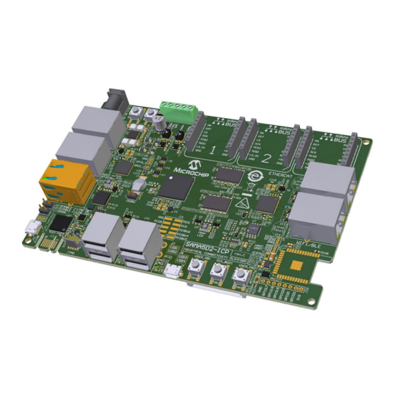
This user's guide describes how to use the SAMA5D2 Industrial Connectivity Platform (SAMA5D2-ICP) kit.
The SAMA5D2-ICP is a hardware and software platform that demonstrates the rich wired and wireless connectivity
solutions around Microchip's SAMA5D2 Arm Cortex-A based microprocessors. It offers customers a starting point for
®
®
their applications that include either EtherCAT, Ethernet 10/100 and 10/100/1000, CAN, Wi-Fi
, Bluetooth
or USB
™
communications, or any combination of these. The board also features three mikroBUS
click interface headers to
™
support over 450 MikroElektronika Click boards
.
Figure 1. SAMA5D2-ICP Board
User Guide
DS60001592A-page 1
©
2020 Microchip Technology Inc.
Advertisement
Table of Contents

Related Manuals for Microchip Technology ATSAMA5D2-ICP


Summary of Contents for Microchip Technology ATSAMA5D2-ICP
-
Page 1: Scope
, Bluetooth or USB ™ communications, or any combination of these. The board also features three mikroBUS click interface headers to ™ support over 450 MikroElektronika Click boards Figure 1. SAMA5D2-ICP Board User Guide DS60001592A-page 1 © 2020 Microchip Technology Inc. -
Page 2: Table Of Contents
The Microchip Website..........................59 Product Change Notification Service......................59 Customer Support............................59 Product Identification System........................60 Microchip Devices Code Protection Feature....................60 Legal Notice..............................60 Trademarks..............................60 Quality Management System........................61 Worldwide Sales and Service........................62 User Guide DS60001592A-page 2 © 2020 Microchip Technology Inc. -
Page 3: Introduction
DS20005514 USB2534 https://www.microchip.com/USB2534 DS00001713 MIC2026/2076 https://www.microchip.com/MIC2026 M9999-060410-B LAN7850 https://www.microchip.com/LAN7850 DS00001993 KSZ8563R https://www.microchip.com/KSZ8563 DS00002418 LAN9252 https://www.microchip.com/LAN9252 DS00001909 24AA512/24LC512/24FC512 https://www.microchip.com/24FC512 DS21754 ATWILC3000-MR110CA https://www.microchip.com/ATWILC3000 DS70005327 93AA66A/B/C, 93LC66A/B/C, 93C66A/B/C https://www.microchip.com/93AA66A DS21795 ATECC608A https://www.microchip.com/ATECC608A DS40001977 User Guide DS60001592A-page 3 © 2020 Microchip Technology Inc. -
Page 4: Product Overview
One PMIC Microchip MCP16502 Power management One power consumption measurement device Microchip PAC1934 µUSB and 2.1mm/5.5mm jack Board supply From J16 and from external connector connector Power saving SuperCap 220 mF@3.3V User Guide DS60001592A-page 4 © 2020 Microchip Technology Inc. -
Page 5: Sama5D2-Icp Kit Content
Through the USB Micro-AB connector on the J-Link-OB Embedded Debugger interface (J16) Table 2-3. Electrical Characteristics Electrical Parameter Value Input voltage 5VCC Maximum input voltage (limits) 6VCC Maximum DC 3.3V current available 1.2A I/O voltage 3.3V only User Guide DS60001592A-page 5 © 2020 Microchip Technology Inc. -
Page 6: Board Components
Closed VDDBU current measurement Erases SAM3U firmware (not populated, reserved for factory configuration, should never be Open used by the end user). Open Enables JTAG-OB (closed=disables JTAG-OB) Open Enables JTAG-CDC (closed=disables JTAG-CDC) User Guide DS60001592A-page 6 © 2020 Microchip Technology Inc. - Page 7 Tampers and PIOs Ethernet 10/100/1000 RJ45 (HSIC) WILC3000 UART debug Ethernet 10/100 RJ45 (Etherswitch Port1) WILC3000 user-free GPIOs Ethernet 10/100 RJ45 (Etherswitch Port2) ETH switch user-free GPIOs EtherCAT RJ45 port A – User Guide DS60001592A-page 7 © 2020 Microchip Technology Inc.
-
Page 8: Function Blocks
DC supply. The red D3 ON LED indicates the presence of a 5V power supply from the wall adapter or from USB. The figure below shows the input power supply topology. User Guide DS60001592A-page 8 © 2020 Microchip Technology Inc. - Page 9 Figure 3-4. Power Supply Connector and USB J-Link-OB Port Location 3.2.1.2 Power Supply Requirements and Restrictions Detailed information on the device power supplies is provided in tables “SAMA5D2 Power Supplies” and “Power Supply Connections” in the SAMA5D2 Series data sheet. User Guide DS60001592A-page 9 © 2020 Microchip Technology Inc.
- Page 10 HIGH by the MPU before completion of the start-up sequence (i.e., when nRSTO is asserted high), the MCP16502 automatically initiates a turn-off sequence. After the assertion of PWRHLD, nSTRT should be released before the long-press time-out timer expires. User Guide DS60001592A-page 10 © 2020 Microchip Technology Inc.
- Page 11 Low-Power mode 2 (achieved through I 2 C programming) High-Z Active FPWM FPWM FPWM FPWM High-Z High-Performance Active FPWM FPWM FPWM FPWM 3.2.1.4.6 I C Interface Description The figure below depicts MCP16502 power management. User Guide DS60001592A-page 11 © 2020 Microchip Technology Inc.
- Page 12 OFF state, as long as the SVIN pin is powered. In the OFF state, the VDDIO voltage from Buck1 is turned off and therefore the I C pullup rail must be provided externally. For more information, refer to the PMIC MCP16502 data sheet. User Guide DS60001592A-page 12 © 2020 Microchip Technology Inc.
- Page 13 SENSE1- VDD I/O SENSE2_P SENSE2+ SM_CLK 0.1uF 0.1uF 2.2uF 2.2uF SENSE2_N SENSE2- SM_DATA 0402 0402 0402 0402 SENSE3_P SENSE3+ PWRDN SENSE3_N SENSE3- SLOW/ALERT PB17 ADDRSEL SENSE4_P SENSE4+ SENSE4_N SENSE4- 0402 PAC1934 User Guide DS60001592A-page 13 © 2020 Microchip Technology Inc.
- Page 14 The main regulators provide all power supplies required by the SAMA5D27 device: • 1.25V VDDCORE, VDDPLLA, VDDUTMIC, VDDHSIC • 1.35V VDDIODDR • 2.5V VDDFUSE • 3.3V VDDIOP0, VDDIOP1, VDDIOP2, VDDISC • 3.3V VDDOSC, VDDUTMI, VDDANA, VDDAUDIOPLL, VDDSDHC • 3.3V VDDBU User Guide DS60001592A-page 14 © 2020 Microchip Technology Inc.
- Page 15 32.768 kHz and one main clock oscillator running at 12 MHz. An optional 12 MHz crystal is available as an alternative to the DSC1001DL5-012.0000 oscillator. Note: PIOBU0 can be used to disable the 12 MHz main oscillator (Y3). User Guide DS60001592A-page 15 © 2020 Microchip Technology Inc.
- Page 16 Reset Circuitry The reset sources for the SAMA5D2-ICP board are: • Power-on Reset from the PMIC MCP16502 • Push button reset SW1 • External JTAG or J-Link-OB reset from an in-circuit emulator User Guide DS60001592A-page 16 © 2020 Microchip Technology Inc.
- Page 17 3.3V P4.6D4.8H1.66 0402 3.2.4 Push Button Switches The SAMA5D2-ICP features five push buttons: • One reset push button (SW1). When pressed and released, it causes a general reset of the board User Guide DS60001592A-page 17 © 2020 Microchip Technology Inc.
- Page 18 Two DDR3L SDRAMs (W632GU6MB 2 Gbits = 16, 777,216 words x 8 banks x 16 bits) are used as main system memory, totalling 4 Gbits of SDRAM on the board. The memory bus is 32 bits wide and operates with a frequency of up to 166 MHz. User Guide DS60001592A-page 18 © 2020 Microchip Technology Inc.
- Page 19 0402 0402 0402 0402 0402 0402 0402 0402 0402 0402 0402 0402 0402 0402 0402 3.2.5.3 DDR_CAL Analog Input One specific analog input, DDR_CAL, is used to calibrate all DDR I/Os. User Guide DS60001592A-page 19 © 2020 Microchip Technology Inc.
- Page 20 With the support of the Quad SPI protocol, the QSPI allows the system to use high-performance serial Flash memories which are small and inexpensive, instead of larger and more expensive parallel Flash memories. The figure below illustrates a socket implementation for the QSPI Flash memory. User Guide DS60001592A-page 20 © 2020 Microchip Technology Inc.
- Page 21 Signal Description PD19 TWD1 EEPROM TWI TWI Data PD20 TWCK1 EEPROM TWI TWI Clock ATECC608A-SSHDA is placed on the same TWI bus as the EEPROM memories and the three mikroBUS connectors. User Guide DS60001592A-page 21 © 2020 Microchip Technology Inc.
- Page 22 The EUI-48 addresses can be assigned as the actual physical address of a system hardware device or node, or it can be assigned to a software instance. These addresses are factory-programmed by Microchip and guaranteed unique. User Guide DS60001592A-page 22 © 2020 Microchip Technology Inc.
- Page 23 SDMMC0 communication is based on an 8-pin interface (clock, command, four data and power lines). It includes a card detection switch. The figure below illustrates the implementation for the SDMMC0 interface. User Guide DS60001592A-page 23 © 2020 Microchip Technology Inc.
- Page 24 Dual port 10/100 Ethernet switch (Microchip KSZ8563) • 1-Gbit Ethernet port (Microchip LAN7850) • EtherCAT dual port (Microchip LAN9252) • USB hub 4 ports (Microchip USB2534) • USB device high-speed port User Guide DS60001592A-page 24 © 2020 Microchip Technology Inc.
- Page 25 When the Reset push button switch is pressed, the device places all pins into their default state. An additional PIO resets the KSZ8563. The figure below illustrates the implementation of the Ethernet switch interface. User Guide DS60001592A-page 25 © 2020 Microchip Technology Inc.
- Page 26 – Receive error PD13 ETH_GRX0 – Receive data 0 PD14 ETH_GRX1 – Receive data 1 ETH_GRX2 – Receive data 2 ETH_GRX3 – Receive data 3 PB30 ETH_GMDC – Management data clock User Guide DS60001592A-page 26 © 2020 Microchip Technology Inc.
- Page 27 DIFF100 3 RX+ RX2_P DIFF100 6 RX- C216 0.1uF 0402 4X 75R RX2_N SHLD SHLD 1nF,2kV SHLD Right Left GND ETH RJ45 J00-0045NL R160 330R 0603 LED2_1 R161 330R 0603 LED2_0 User Guide DS60001592A-page 27 © 2020 Microchip Technology Inc.
- Page 28 EARTH / GND Common ground ACT LED LED activity ACT LED LED activity LINK LED LED link connection LINK LED LED link connection EARTH / GND Common ground EARTH / GND Common ground User Guide DS60001592A-page 28 © 2020 Microchip Technology Inc.
- Page 29 EEPROM or OTP are reloaded. An additional PIO (PC2) allows the LAN7850 to be reset by software. The figure below illustrates the implementation of the Ethernet HSIC interface. User Guide DS60001592A-page 29 © 2020 Microchip Technology Inc.
- Page 30 Indicates Power Management Event when the PME mode of operation is in PC23 PME_N – effect Serves as the Power Management Event mode selection input when the PME PC24 PME_MODE – mode of operation is in effect User Guide DS60001592A-page 30 © 2020 Microchip Technology Inc.
- Page 31 When the Reset push button switch is pressed, the device places all pins into their default state. An additional PIO (PB16) allows the LAN9252 to be reset by software. The figure below illustrates the implementation of the EtherCAT interface. User Guide DS60001592A-page 31 © 2020 Microchip Technology Inc.
- Page 32 The table below shows the signal assignment on the HBI interface between SAMA5D27 and LAN9252. Table 3-14. EBI Signal Description Mnemonic Shared Signal Description PA22 WILC3000 Data PA23 – Data PA24 – Data User Guide DS60001592A-page 32 © 2020 Microchip Technology Inc.
- Page 33 – Address – Read PA30 – Write – Chip select PB11 – Interrupt PB16 RESET – Reset chip The figure below depicts the connection between LAN9252 and the two EtherCAT connectors. User Guide DS60001592A-page 33 © 2020 Microchip Technology Inc.
- Page 34 10pF 10pF 10pF 0.022uF Left B0520WS rxb_n 0402 0402 0402 0402 0603 RJ45 Earth ETH1 J00-0045NL GPIO1 R262 0402 The position of the two connectors is shown in the picture below User Guide DS60001592A-page 34 © 2020 Microchip Technology Inc.
- Page 35 Host Controller Interface) protocol as well as the Enhanced HCI (Enhanced Host Controller Interface) protocol. The USB Host Port User interface can be found in the Enhanced HCI Rev 1.0 Specification. User Guide DS60001592A-page 35 © 2020 Microchip Technology Inc.
- Page 36 5V power Data minus Data plus Not connected Common ground 3.2.8.6.1 USB-A VBUS Detection The USB-A port (J9) features a VBUS (+5V) insert detection function through ladder-type resistors R129 and R130. User Guide DS60001592A-page 36 © 2020 Microchip Technology Inc.
- Page 37 100k VDDCR12 SCL/SMBCLK/CFG_SEL0 R122 100k HS_IND/CFG_SEL1 C146 C135 R123 0.1uF 100k SUSP_IND/LOCAL_PWR/NON_REM0 R124 0603 0402 USB2534I-1080AEN The picture below shows the location of the two double stacked connectors, J7 and J8. User Guide DS60001592A-page 37 © 2020 Microchip Technology Inc.
- Page 38 LD1 to LD4 indicate when 5V DC port power is available to the associated downstream USB port(s). 3.2.8.7.3 Connectors The USB2534 interface provides four connectors of type A for downstream ports. For more details on the pinout of these connectors, refer to the USB2534 schematics. User Guide DS60001592A-page 38 © 2020 Microchip Technology Inc.
- Page 39 Application note AN_3227, How to Manually Solder the ATWILC3000 Module on an MPU Board, offers guidance on how to add the ATWILC3000 module to the board. User Guide DS60001592A-page 39 © 2020 Microchip Technology Inc.
- Page 40 Bluetooth serial TX BT_RXD QSPI Bluetooth serial RX PA10 BT_RTS QSPI Bluetooth serial RTS BT_CTS QSPI Bluetooth serial CTS RESET_N – Module reset PC14 IRQ_N – Interrupt PC15 CHIP_EN – Chip enable User Guide DS60001592A-page 40 © 2020 Microchip Technology Inc.
- Page 41 The transmitter and the high-speed comparator are switched off to reduce the power current consumption. For more details on the module, refer to the product web page. The figure below illustrates the implementation of the dual CAN interface. User Guide DS60001592A-page 41 © 2020 Microchip Technology Inc.
- Page 42 Table 3-19. CAN Connector J6 Signal Description Pin No Mnemonic Signal Description CAN0H Differential positive port 0 CAN0L Differential negative port 0 Common ground CAN1H Differential positive port 1 CAN1L Differential negative port 1 User Guide DS60001592A-page 42 © 2020 Microchip Technology Inc.
-
Page 43: External Interfaces
Power enabled on USB3 Green Power enabled on USB4 Green Power enabled on USB1 Green Power enabled on USB2 Ethernet HISC LAN7850 “DUPLEX/COLLISION” Green Ethernet HISC LAN7850 “LINK/ACTIVITY” Blue Ethernet HISC LAN7850 “SUSPEND” J-Link-OB/J-Link-CDC User Guide DS60001592A-page 43 © 2020 Microchip Technology Inc. - Page 44 The picture below shows the positions of LEDs described above Figure 3-36. On-Board LEDs 3.3.1.1 RGB LED The SAMA5D2-ICP board features one RGB LED. The three LED cathodes are controlled via GPIO PWM pins. User Guide DS60001592A-page 44 © 2020 Microchip Technology Inc.
-
Page 45: Debugging Capability
A 10-pin JTAG header (J18) is provided on the SAMA5D2-ICP board to facilitate software development and debug by using various JTAG emulators. The interface signals have a voltage level of 3.3V. User Guide DS60001592A-page 45 © 2020 Microchip Technology Inc. - Page 46 Table 3-22. JTAG/ICE Connector J18 Pin Assignment Signal Descriptions Pin No Mnemonic Signal Description VTref. 3.3V power Target reference voltage (main 3.3V) TMS (Test Mode Select) JTAG mode set input into target CPU Common ground User Guide DS60001592A-page 46 © 2020 Microchip Technology Inc.
- Page 47 The table below describes the COM port debug interface signals. Table 3-23. Debug COM Port PIOs Signal Descriptions Mnemonic Shared Signal Description PB26 URXD0 DEBUG Receive data PB27 UTXD0 DEBUG Transmit data User Guide DS60001592A-page 47 © 2020 Microchip Technology Inc.
- Page 48 Jumper JP19 not installed: J-Link-OB-ATSAM3U4C is enabled and fully functional. • Jumper JP19 installed: J-Link-OB-ATSAM3U4C is disabled and an external JTAG controller can be used through the 10-pin JTAG port J18 User Guide DS60001592A-page 48 © 2020 Microchip Technology Inc.
- Page 49 , as a /dev/ACMx device. This enables the user to use host software which was not designed to be used with USB, such as a terminal program, giving access to UART0 on the SAMA5D27. User Guide DS60001592A-page 49 © 2020 Microchip Technology Inc.
-
Page 50: Pio Usage On Expansion Connectors
PIOBU3 R225 R233 330R 330R PIOBU4 PIOBU5 R226 R234 330R PIOBU6 PC30 R227 R235 PC25 R228 PD31 HDR-2.54 Male 2x5 The table below describes the pin assignment of PIOBU connector J24. User Guide DS60001592A-page 50 © 2020 Microchip Technology Inc. - Page 51 (SPI, UART and TWI), four additional pins (PWM, interrupt, analog input and reset) and two power groups (+3.3V and GND on the left, and 5V and GND on the right 1x8 header). The figures below illustrates the implementation of the mikroBUS interfaces. User Guide DS60001592A-page 51 © 2020 Microchip Technology Inc.
- Page 52 MISO PD22_MKBUS2 MikroBus2 MOSI TWD0 PB28 MOSI PD21_MKBUS2 +3.3V mikroBUS HOST Table 3-27. mikroBUS2 Connector J22 Pin Assignment SAMA5D27 SAMA5D27 Function MBUS Signal Pin No. MBUS Signal Function Analog input PD25 PB23 User Guide DS60001592A-page 52 © 2020 Microchip Technology Inc.
- Page 53 UART_TX UART transmit SPI MISO PA16 SPI_MISO TWI_SCL PD22 TWI clock SPI MOSI PA15 SPI_MOSI TWI_SDA PD21 TWI data 3.3VCC – 3.3V supply 5V Supply – 5VDD Ground – – Ground User Guide DS60001592A-page 53 © 2020 Microchip Technology Inc.
- Page 54 ATSAMA5D2-ICP Board Components Figure 3-48. mikroBUS Connectors Location User Guide DS60001592A-page 54 © 2020 Microchip Technology Inc.
-
Page 55: Board Layout
N11 N12 N14 N15 N16 N17 U11 U12 U14 U15 U16 U17 15 16 17 18 19 20 21 22 23 24 25 26 27 28 26 25 24 22 21 20 User Guide DS60001592A-page 55 © 2020 Microchip Technology Inc. - Page 56 ATSAMA5D2-ICP Board Layout Figure 4-2. Board Assembly Drawing - Bottom User Guide DS60001592A-page 56 © 2020 Microchip Technology Inc.
-
Page 57: Installation And Operation
Connect the other end of the cable to a free port of your PC. Open a terminal (console 115200, N, 8, 1) on your Personal Computer. Reset the baseboard. A start-up message appears on the console. User Guide DS60001592A-page 57 © 2020 Microchip Technology Inc. -
Page 58: Revision History
ATSAMA5D2-ICP Revision History Revision History Rev. A - 02/2020 First issue. User Guide DS60001592A-page 58 © 2020 Microchip Technology Inc. -
Page 59: The Microchip Website
Customers should contact their distributor, representative or ESE for support. Local sales offices are also available to help customers. A listing of sales offices and locations is included in this document. Technical support is available through the website at: http://www.microchip.com/support User Guide DS60001592A-page 59 © 2020 Microchip Technology Inc. -
Page 60: Product Identification System
HyperLight Load, IntelliMOS, Libero, motorBench, mTouch, Powermite 3, Precision Edge, ProASIC, ProASIC Plus, ProASIC Plus logo, Quiet-Wire, SmartFusion, SyncWorld, Temux, TimeCesium, TimeHub, TimePictra, TimeProvider, Vite, WinPath, and ZL are registered trademarks of Microchip Technology Incorporated in the U.S.A. Adjacent Key Suppression, AKS, Analog-for-the-Digital Age, Any Capacitor, AnyIn, AnyOut, BlueSky, BodyCom, CodeGuard, CryptoAuthentication, CryptoAutomotive, CryptoCompanion, CryptoController, dsPICDEM, dsPICDEM.net, Dynamic Average Matching, DAM, ECAN, EtherGREEN, In-Circuit Serial Programming, ICSP,... -
Page 61: Quality Management System
The Adaptec logo, Frequency on Demand, Silicon Storage Technology, and Symmcom are registered trademarks of Microchip Technology Inc. in other countries. GestIC is a registered trademark of Microchip Technology Germany II GmbH & Co. KG, a subsidiary of Microchip Technology Inc., in other countries. -
Page 62: Worldwide Sales And Service
New York, NY Tel: 46-31-704-60-40 Tel: 631-435-6000 Sweden - Stockholm San Jose, CA Tel: 46-8-5090-4654 Tel: 408-735-9110 UK - Wokingham Tel: 408-436-4270 Tel: 44-118-921-5800 Canada - Toronto Fax: 44-118-921-5820 Tel: 905-695-1980 Fax: 905-695-2078 User Guide DS60001592A-page 62 © 2020 Microchip Technology Inc.
Need help?
Do you have a question about the ATSAMA5D2-ICP and is the answer not in the manual?
Questions and answers