Table of Contents
Advertisement
Quick Links
ATtiny1607 Curiosity Nano
ATtiny1607 Curiosity Nano Hardware User Guide
Preface
The ATtiny1607 Curiosity Nano evaluation kit is a hardware platform to evaluate the ATtiny1607
microcontroller.
®
Supported by Atmel Studio/Microchip MPLAB
X Integrated Development Environment (IDE), the kit
provides easy access to the features of the ATtiny1607 to explore how to integrate the device into a
custom design.
The Curiosity Nano series of evaluation kits include an on-board debugger. No external tools are
necessary to program and debug the ATtiny1607.
User Guide
DS50002897A-page 1
©
2019 Microchip Technology Inc.
Advertisement
Table of Contents

Related Manuals for Microchip Technology ATtiny1607 Curiosity Nano


Summary of Contents for Microchip Technology ATtiny1607 Curiosity Nano
-
Page 1: Preface
ATtiny1607 Curiosity Nano ATtiny1607 Curiosity Nano Hardware User Guide Preface The ATtiny1607 Curiosity Nano evaluation kit is a hardware platform to evaluate the ATtiny1607 microcontroller. ® Supported by Atmel Studio/Microchip MPLAB X Integrated Development Environment (IDE), the kit provides easy access to the features of the ATtiny1607 to explore how to integrate the device into a custom design. -
Page 2: Table Of Contents
VBUS Output Pin......................11 3.4. Target Current Measurement..................... 12 3.5. Disconnecting the On-Board Debugger..................13 4. Hardware User Guide....................15 4.1. Connectors..........................15 4.1.1. ATtiny1607 Curiosity Nano Pinout................15 4.1.2. Using Pin Headers.......................15 4.2. Peripherals..........................16 4.2.1. LED..........................16 4.2.2. Mechanical Switch....................... 16 4.2.3. - Page 3 ATtiny1607 Curiosity Nano 7. Appendix........................21 7.1. Schematic...........................21 7.2. Assembly Drawing........................23 ™ 7.3. Curiosity Nano Base for Click boards ..................24 7.4. Connecting External Debuggers....................25 7.5. Getting Started with IAR......................26 The Microchip Website....................29 Product Change Notification Service................29 Customer Support......................29 Microchip Devices Code Protection Feature..............
-
Page 4: Introduction
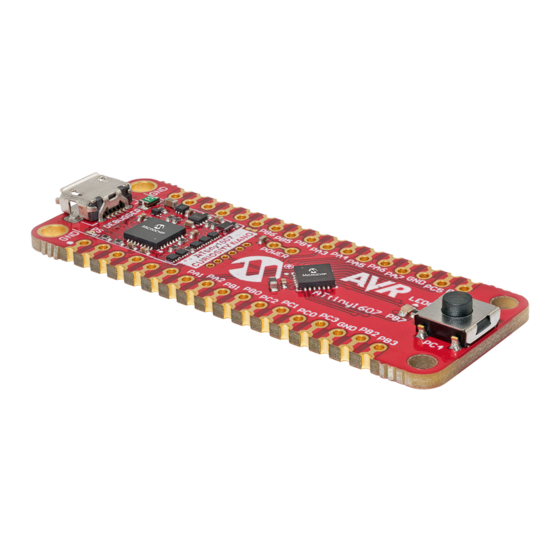
– 1.8-5.1V output voltage (limited by USB input voltage) – 500 mA maximum output current (limited by ambient temperature and output voltage) Kit Overview The Microchip ATtiny1607 Curiosity Nano evaluation kit is a hardware platform to evaluate the ATtiny1607 microcontroller. Figure 1-1. ATtiny1607 Curiosity Nano Evaluation Kit Overview... -
Page 5: Getting Started
Curiosity Nano and Xplained Pro boards and COM Ports. • ATtiny1607 Curiosity Nano website - Kit information, latest user guide and design documentation. • ATtiny1607 Curiosity Nano on Microchip Direct - Purchase this kit on Microchip Direct. User Guide DS50002897A-page 5 ©... -
Page 6: Curiosity Nano
The Virtual COM port is connected to a UART on the ATtiny1607 and provides an easy way to communicate with the target application through terminal software. The on-board debugger controls a Power and Status LED (marked PS) on ATtiny1607 Curiosity Nano. The table below shows how the LED is controlled in different operation modes. -
Page 7: Limitations
ATtiny1607 Curiosity Nano Curiosity Nano On Linux machines, the CDC will enumerate and appear as /dev/ttyACM#. On MAC machines, the CDC will enumerate and appear as /dev/tty.usbmodem#. Depending on which terminal program is used, it will appear in the available list of modems as usbmodem#. -
Page 8: Mass Storage Disk
ATtiny1607 Curiosity Nano Curiosity Nano The default baud rate used in this mode is 9600 bps, but if the CDC is already active or has been configured, the baud rate last used still applies. USB-Level Framing Considerations Sending data from the host to the CDC can be done byte-wise or in blocks, which will be chunked into 64- byte USB frames. -
Page 9: Fuse Bytes
ATtiny1607 Curiosity Nano Curiosity Nano • KIT-INFO.TXT - a text file containing details about the kit firmware, name, serial number, and device. • STATUS.TXT - a text file containing the programming status of the board. Info: STATUS.TXT is dynamically updated by the on-board debugger, the contents may be cached by the OS and therefore not reflect the correct status. -
Page 10: Power Supply
ATtiny1607 microcontroller. The voltage limits configured in the on-board debugger on ATtiny1607 Curiosity Nano are 1.8-5.1V. User Guide DS50002897A-page 10 ©... -
Page 11: External Supply
VBUS Output Pin ATtiny1607 Curiosity Nano has a VBUS output pin which can be used to power external components that need a 5V supply. The VBUS output pin has a PTC fuse to protect the USB against short circuits. A side... -
Page 12: Target Current Measurement
ATtiny1607 Curiosity Nano Curiosity Nano effect of the PTC fuse is a voltage drop on the VBUS output with higher current loads. The chart below shows the voltage versus the current load of the VBUS output. Figure 3-4. VBUS Output Voltage vs. Current... -
Page 13: Disconnecting The On-Board Debugger
ATtiny1607 Curiosity Nano Curiosity Nano Tip: A 100-mil pin header can be soldered into the Target Power strap (J101) footprint for easy connection of an ammeter. Once the ammeter is not needed anymore, place a jumper-cap on the pin header. - Page 14 ATtiny1607 Curiosity Nano Curiosity Nano Tip: Solder in 0Ω resistors across the footprints or short-circuit them with tin solder to reconnect any cut signals. Figure 3-7. Kit Modifications GPIO straps (bottom side) Power Supply strap (top side) User Guide DS50002897A-page 14 ©...
-
Page 15: Hardware User Guide
Using Pin Headers The edge connector footprint on ATtiny1607 Curiosity Nano has a staggered design where each of the holes is shifted 8 mil (~0.2 mm) off center. The hole shift allows the use of regular 100-mil pin headers on the kit without soldering. -
Page 16: Peripherals
Peripherals 4.2.1 There is one yellow user LED available on the ATtiny1607 Curiosity Nano kit that can be controlled by either GPIO or PWM. The LED can be activated by driving the connected I/O line to GND. Table 4-1. LED Connection... - Page 17 ATtiny1607 Curiosity Nano Hardware User Guide Table 4-3. On-Board Debugger Connections ATtiny1607 Pin Debugger Pin Function Shared Functionality CDC TX UART RX (ATtiny1607 RX line) Edge connector CDC RX UART TX (ATtiny1607 TX line) Edge connector UPDI DBG0 UPDI DBG1 GPIO...
-
Page 18: Hardware Revision History And Known Issues
Identifying Product ID and Revision The revision and product identifier of the ATtiny1607 Curiosity Nano can be found in two ways; either ®... - Page 19 Revision 1 does not have the Target Power strap described in 3.4 Target Current Measurement. Instead, the current can be measured across the Power Supply strap, as described in 3.5 Disconnecting the On- Board Debugger. Figure 5-1. ATtiny1607 Curiosity Nano Revision 1 User Guide DS50002897A-page 19 © 2019 Microchip Technology Inc.
-
Page 20: Document Revision History
ATtiny1607 Curiosity Nano Document Revision History Document Revision History Doc. rev. Date Comment 06/2019 Initial document release. User Guide DS50002897A-page 20 © 2019 Microchip Technology Inc. -
Page 21: Appendix
ATtiny1607 Curiosity Nano Appendix Appendix Schematic Figure 7-1. ATtiny1607 Curiosity Nano Schematic User Guide DS50002897A-page 21 © 2019 Microchip Technology Inc. - Page 22 ATtiny1607 Curiosity Nano Appendix User Guide DS50002897A-page 22 © 2019 Microchip Technology Inc.
-
Page 23: Assembly Drawing
ATtiny1607 Curiosity Nano Appendix Assembly Drawing Figure 7-2. ATtiny1607 Curiosity Nano Assembly Drawing Top Figure 7-3. ATtiny1607 Curiosity Nano Assembly Drawing Bottom User Guide DS50002897A-page 23 © 2019 Microchip Technology Inc. -
Page 24: Curiosity Nano Base For Click Boards
ATtiny1607 Curiosity Nano Appendix ™ Curiosity Nano Base for Click boards Figure 7-4. ATtiny1607 Curiosity Nano Pinout Mapping VBUS DBG3 VOFF DBG0 CDC TX DBG2 CDC RX DBG1 User Guide DS50002897A-page 24 © 2019 Microchip Technology Inc. -
Page 25: Connecting External Debuggers
ATtiny1607 Curiosity Nano Appendix Connecting External Debuggers Even though there is an on-board debugger, external debuggers can be connected directly to ATtiny1607 Curiosity Nano to program/debug the ATtiny1607. The on-board debugger keeps all the pins connected to the ATtiny1607 and board edge in tri-state when not actively used. Therefore, the on-board debugger will not interfere with any external debug tools. -
Page 26: Getting Started With Iar
™ GCC. Programming and debugging of ATtiny1607 Curiosity Nano is supported in IAR Embedded Workbench for AVR using the Atmel-ICE interface. Some initial settings must be set up in the project to get the programming and debugging to work. - Page 27 ATtiny1607 Curiosity Nano Appendix In the category Debugger > Atmel-ICE, select the Atmel-ICE 1 tab. Select UPDI as the interface and, optionally, select the UPDI frequency. Info: If the selection of Debug Port, mentioned in step 4, is grayed out, the interface is preselected, and the user can skip this configuration step.
- Page 28 ATtiny1607 Curiosity Nano Appendix Figure 7-8. Select Debugger Figure 7-9. Configure Interface User Guide DS50002897A-page 28 © 2019 Microchip Technology Inc.
-
Page 29: The Microchip Website
ATtiny1607 Curiosity Nano The Microchip Website Microchip provides online support via our website at http://www.microchip.com/. This website is used to make files and information easily available to customers. Some of the content available includes: • Product Support – Data sheets and errata, application notes and sample programs, design resources, user’s guides and hardware support documents, latest software releases and archived... -
Page 30: Legal Notice
PICSTART, PIC32 logo, PolarFire, Prochip Designer, QTouch, SAM-BA, SenGenuity, SpyNIC, SST, SST Logo, SuperFlash, Symmetricom, SyncServer, Tachyon, TempTrackr, TimeSource, tinyAVR, UNI/O, Vectron, and XMEGA are registered trademarks of Microchip Technology Incorporated in the U.S.A. and other countries. APT, ClockWorks, The Embedded Control Solutions Company, EtherSynch, FlashTec, Hyper Speed... -
Page 31: Quality Management System
ATtiny1607 Curiosity Nano GestIC is a registered trademark of Microchip Technology Germany II GmbH & Co. KG, a subsidiary of Microchip Technology Inc., in other countries. All other trademarks mentioned herein are property of their respective companies. © 2019, Microchip Technology Incorporated, Printed in the U.S.A., All Rights Reserved. -
Page 32: Worldwide Sales And Service
New York, NY Tel: 46-31-704-60-40 Tel: 631-435-6000 Sweden - Stockholm San Jose, CA Tel: 46-8-5090-4654 Tel: 408-735-9110 UK - Wokingham Tel: 408-436-4270 Tel: 44-118-921-5800 Canada - Toronto Fax: 44-118-921-5820 Tel: 905-695-1980 Fax: 905-695-2078 User Guide DS50002897A-page 32 © 2019 Microchip Technology Inc.
Need help?
Do you have a question about the ATtiny1607 Curiosity Nano and is the answer not in the manual?
Questions and answers