Table of Contents
Advertisement
Quick Links
ATtiny3217 Xplained Pro
ATtiny3217 Xplained Pro
Preface
The ATtiny3217 Xplained Pro evaluation kit is a hardware platform to evaluate the ATtiny3217 microcontroller.
®
Supported by the Atmel Studio and MPLAB
X integrated development platform, the kit provides easy access to the
features of the ATtiny3217 and explains how to integrate the device into a custom design.
The Xplained Pro MCU series evaluation kits include on-board Embedded Debuggers. No external tools are
necessary to program or debug the ATtiny3217.
Xplained Pro extension kits offer additional peripherals to extend the features of the board and ease the development
of custom designs.
User Guide
DS50002765B-page 1
©
2020 Microchip Technology Inc.
Advertisement
Table of Contents

Related Manuals for Microchip Technology ATtiny3217 Xplained Pro


Summary of Contents for Microchip Technology ATtiny3217 Xplained Pro
-
Page 1: Preface
ATtiny3217 Xplained Pro ATtiny3217 Xplained Pro Preface The ATtiny3217 Xplained Pro evaluation kit is a hardware platform to evaluate the ATtiny3217 microcontroller. ® Supported by the Atmel Studio and MPLAB X integrated development platform, the kit provides easy access to the features of the ATtiny3217 and explains how to integrate the device into a custom design. -
Page 2: Table Of Contents
ATtiny3217 Xplained Pro Table of Contents Preface................................1 Introduction............................. 4 1.1. Features............................4 1.2. Kit Overview..........................4 Getting Started............................6 2.1. Xplained Pro Quick Start......................6 2.2. Design Documentation and Relevant Links................. 6 Xplained Pro............................7 3.1. Embedded Debugger........................7 3.2. - Page 3 ATtiny3217 Xplained Pro 6.2. Revision 4...........................25 6.3. Revision 3...........................25 6.4. Revision 2...........................25 Document Revision History........................26 The Microchip Website..........................27 Product Change Notification Service......................27 Customer Support............................27 Microchip Devices Code Protection Feature....................27 Legal Notice..............................27 Trademarks..............................28 Quality Management System........................28 Worldwide Sales and Service........................29...
-
Page 4: Introduction
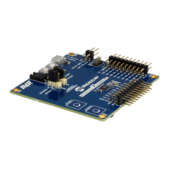
Supported With Application Examples In Atmel START Kit Overview The ATtiny3217 Xplained Pro evaluation kit is a hardware platform to evaluate the ATtiny3217. The kit offers a set of features that enables the ATtiny3217 user to get started with the ATtiny3217 peripherals right away and to get an understanding of how to integrate the device into their design. - Page 5 ATtiny3217 Xplained Pro Introduction Figure 1-1. ATtiny3217 Xplained Pro Evaluation Kit Overview CURRENT MEASUREMENT SW0 USER BUTTON HEADER SW1 USER BUTTON DEBUG USB USER LED0 POWER HEADER UPDI DEBUG FOR EXTERNAL MCU CURRENT DEBUGGER MEASUREMENT SELECT JUMPER I/O CURRENT ATTINY3217 MEASUREMENT...
-
Page 6: Getting Started
The ATtiny3217 device is programmed and debugged by the on-board embedded debugger and, therefore, no external programmer or debugger tool is required. Design Documentation and Relevant Links The following list contains links to the most relevant documents and software for the ATtiny3217 Xplained Pro. • Xplained Products - Xplained Evaluation Kits are a series of easy-to-use evaluation kits for Microchip microcontrollers and other Microchip products. -
Page 7: Xplained Pro
DGI. The EDBG controls two LEDs on the ATtiny3217 Xplained Pro; a power LED and a status LED. The following table provides details on how the LEDs are controlled in different operation modes. -
Page 8: Xplained Pro Analog Module (Xam)
ATtiny3217 Xplained Pro Xplained Pro Xplained Pro Analog Module (XAM) 3.2.1 Overview The Xplained Pro Analog Module (XAM) extends the embedded debugger with a high dynamic range current measurement. This enables power profiling of the target system. Figure 3-1. XAM Block Diagram... -
Page 9: Sample Rate
ATtiny3217 Xplained Pro Xplained Pro • Reference clock: Reference clock for the XAM. 3.2.3 Sample Rate The raw sampling rate of the XAM is up to 250 kHz, and with the default averaging configuration (average of 16 samples), the actual output of the XAM is 16.67 ksps. -
Page 10: Power Sources
3600 Maximum current [mA] uint16_t Power Sources The ATtiny3217 Xplained Pro kit can be powered by several power sources, as listed in the following table. Table 3-4. Power Sources for ATtiny3217 Xplained Pro Power Source Voltage Requirements Current Requirements Connector Marking External power 5V ±2% (±100 mV) for USB... -
Page 11: Xplained Pro Power Header
Xplained Pro Power Header The power header can be used to connect external power to the ATtiny3217 Xplained Pro kit. The kit automatically detects and switches to an external power source, if supplied. The power header can also be used to supply power to external peripherals or extension boards. -
Page 12: Hardware User Guide
Power Distribution ATtiny3217 Xplained Pro has two power sources; EDBG USB and external 5.0V. The kit will automatically select the power source. The kit has two on-board 3.3V voltage regulators; one for the EDBG and XAM, and one for the ATtiny3217 and other peripherals. -
Page 13: Xplained Pro Standard Extension Headers
Xplained Pro Standard Extension Headers The ATtiny3217 Xplained Pro headers EXT1 and EXT3 offer access to the I/O of the microcontroller in order to expand the board, e.g., by connecting extensions to the board. These headers are based on the standard extension header specified in the table below. - Page 14 ATtiny3217 Xplained Pro Hardware User Guide ...continued EXT1 Pin ATtiny3217 Pin Function Shared Functionality 8 [PWM(-)] TC/W1 9 [IRQ/GPIO] IRQ/GPIO - 10 [SPI_SS_B/GPIO] GPIO 11 [I²C_SDA] I²C SDA EXT3 EDBG I²C 12 [I²C_SCL] I²C SCL EXT3 EDBG I²C 13 [USART_RX]...
-
Page 15: Updi Debug Connector
Note: Signal functions in italic use alternative pin location. These have to be configured in the PORTMUX register of the device. 4.2.2 UPDI Debug Connector ATtiny3217 Xplained Pro has a 10-pin 50-mil UPDI Debug Connector that can be used to attach external debuggers to the ATtiny3217. Table 4-3. UPDI Debug Connector UPDI Debug Connector... -
Page 16: Crystal
Microchip. There is a 9 pF, 32.768 kHz crystal in a 3.2 mm by 1.5 mm package mounted on ATtiny3217 Xplained Pro. Info: The crystal is not connected to the device by default, as the crystal pins on the device are shared with the UART module. -
Page 17: Embedded Debugger Implementation
EXT1 Embedded Debugger Implementation The ATtiny3217 Xplained Pro contains an Embedded Debugger (EDBG), which can be used to program and debug the ATtiny3217 using Unified Program Debug Interface (UPDI). The Embedded Debugger also includes a Virtual COM Port interface over UART, a Data Gateway Interface over SPI, I C, and two ATtiny3217 GPIOs. -
Page 18: Xam Configuration
XAM Configuration On the ATtiny3217 Xplained Pro, the MCU and the MCU peripherals (e.g., extensions) are powered by their own regulator, as shown in the figure below. All the other parts of the board, mainly the embedded debugger and the accompanying Xplained Pro Analog Module (XAM), are powered from a separate regulator. -
Page 19: Kit Modifications
XAM. Place both jumpers on the “I/O” and “MCU” headers in the “MEASURE” position. Kit Modifications ATtiny3217 Xplained Pro has several resistors that can be used to disconnect I/O pins of the ATtiny3217 from connectors and on-board ICs and to disconnect power signals. - Page 20 ATtiny3217 Xplained Pro Hardware User Guide ...continued Designat Value Mounted From Comment R406 EDBG CDC RX PB2 UART TX EDBG CDC and DGI interfaces to the ATtiny3217 R407 EDBG I C SDA PA1 I C SDA R408 EDBG I C SCL...
-
Page 21: Connecting The 32.768 Khz Crystal
Connecting the 32.768 kHz Crystal The ATtiny3217 Xplained Pro board has a 32.768 kHz crystal mounted on the kit. The crystal is not connected by default as the TOSC pins on the device are used for UART communication to the extension headers and the EDBG CDC. - Page 22 Applying a voltage higher than 5.5V may damage the board permanently. Figure 4-6. ATtiny3217 Xplained Pro EDBG Disconnect EDBG UPDI , I2C, GPIO, CDC, and SPI disconnect Figure 4-7. ATtiny3217 Xplained Pro Current Measurement Headers Related Links 3.5.2 Xplained Pro Power Header 4.2 Connectors 4.2.2 UPDI Debug Connector...
-
Page 23: Appendix
GCC. Programming and ™ debugging of ATtiny3217 Xplained Pro is supported in IAR Embedded Workbench for AVR using the Atmel-ICE interface. Some initial settings must be set up in the project to get the programming and debugging to work. - Page 24 ATtiny3217 Xplained Pro Appendix Figure 5-2. Select Debugger Figure 5-3. Configure Interface User Guide DS50002765B-page 24 © 2020 Microchip Technology Inc.
-
Page 25: Hardware Revision History And Known Issues
"nnnnrrssssssssss" n = product identifier r = revision s = serial number The product identifier for the ATtiny3217 Xplained Pro is A09-2835. Revision 4 32.768 kHz crystal manufacturer changed. Revision 3 Revision 3 is identical to revision 2, but with ATtiny3217 production samples. -
Page 26: Document Revision History
ATtiny3217 Xplained Pro Document Revision History Document Revision History Doc. rev. Date Comment 02/2020 HW revision 3 and 4 added. 32.768 kHz crystal information updated. 06/2018 Initial document release User Guide DS50002765B-page 26 © 2020 Microchip Technology Inc. -
Page 27: The Microchip Website
ATtiny3217 Xplained Pro The Microchip Website Microchip provides online support via our website at http://www.microchip.com/. This website is used to make files and information easily available to customers. Some of the content available includes: • Product Support – Data sheets and errata, application notes and sample programs, design resources, user’s guides and hardware support documents, latest software releases and archived software •... -
Page 28: Trademarks
The Adaptec logo, Frequency on Demand, Silicon Storage Technology, and Symmcom are registered trademarks of Microchip Technology Inc. in other countries. GestIC is a registered trademark of Microchip Technology Germany II GmbH & Co. KG, a subsidiary of Microchip Technology Inc., in other countries. -
Page 29: Worldwide Sales And Service
New York, NY Tel: 46-31-704-60-40 Tel: 631-435-6000 Sweden - Stockholm San Jose, CA Tel: 46-8-5090-4654 Tel: 408-735-9110 UK - Wokingham Tel: 408-436-4270 Tel: 44-118-921-5800 Canada - Toronto Fax: 44-118-921-5820 Tel: 905-695-1980 Fax: 905-695-2078 User Guide DS50002765B-page 29 © 2020 Microchip Technology Inc.
Need help?
Do you have a question about the ATtiny3217 Xplained Pro and is the answer not in the manual?
Questions and answers