Table of Contents
Advertisement
Quick Links
ATtiny1627 Curiosity Nano Hardware User Guide
Preface
The ATtiny1627 Curiosity Nano Evaluation Kit is a hardware platform to evaluate microcontrollers in the tinyAVR
series. This board has the ATtiny1627 microcontroller (MCU) mounted.
Supported by Atmel Studio and Microchip MPLAB
provides easy access to the features of the ATtiny1627 to explore how to integrate the device into a custom design.
The Curiosity Nano series of evaluation boards include an on-board debugger. No external tools are necessary to
program and debug the ATtiny1627.
®
•
MPLAB
X IDE
and
Atmel Studio
microcontrollers.
•
ATtiny1627 website
•
ATtiny1627 Curiosity Nano website
•
Code examples on GitHub
©
2020 Microchip Technology Inc.
®
X Integrated Development Environments (IDEs), the board
- Software to discover, configure, develop, program, and debug Microchip
- Find documentation, sample, and purchase microcontrollers.
- Kit information, latest user guide and design documentation.
- Get started with code examples.
User Guide
ATtiny1627
DS40002199A-page 1
®
2-
Advertisement
Table of Contents

Subscribe to Our Youtube Channel
Related Manuals for Microchip Technology ATtiny1627 Curiosity Nano


Summary of Contents for Microchip Technology ATtiny1627 Curiosity Nano
-
Page 1: Preface
ATtiny1627 Curiosity Nano Hardware User Guide Preface ® The ATtiny1627 Curiosity Nano Evaluation Kit is a hardware platform to evaluate microcontrollers in the tinyAVR series. This board has the ATtiny1627 microcontroller (MCU) mounted. ® Supported by Atmel Studio and Microchip MPLAB X Integrated Development Environments (IDEs), the board provides easy access to the features of the ATtiny1627 to explore how to integrate the device into a custom design. -
Page 2: Table Of Contents
3.5.4. Connecting to External Microcontrollers..............20 3.6. Connecting External Debuggers....................21 Hardware User Guide........................... 24 4.1. Connectors..........................24 4.1.1. ATtiny1627 Curiosity Nano Pinout................24 4.1.2. Using Pin Headers.......................24 4.2. Peripherals..........................25 User Guide DS40002199A-page 2 © 2020 Microchip Technology Inc. - Page 3 Getting Started with IAR......................34 The Microchip Website..........................37 Product Change Notification Service......................37 Customer Support............................37 Microchip Devices Code Protection Feature....................37 Legal Notice..............................37 Trademarks..............................38 Quality Management System........................38 Worldwide Sales and Service........................39 User Guide DS40002199A-page 3 © 2020 Microchip Technology Inc.
-
Page 4: Introduction
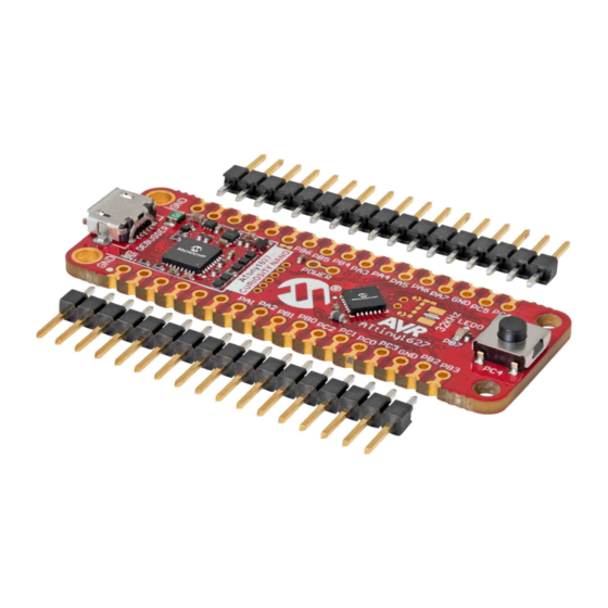
– 1.8-5.1V output voltage (limited by USB input voltage) – 500 mA maximum output current (limited by ambient temperature and output voltage) Kit Overview The Microchip ATtiny1627 Curiosity Nano Evaluation Kit is a hardware platform to evaluate the ATtiny1627 microcontroller. Figure 1-1. ATtiny1627 Curiosity Nano Evaluation Kit Overview... -
Page 5: Getting Started
Tip: The Kit Window can be opened in MPLAB X IDE through the menu bar Window > Kit Window. Design Documentation and Relevant Links The following list contains links to the most relevant documents and software for the ATtiny1627 Curiosity Nano Board: ®... - Page 6 Microchip development boards, ready to be adapted and extended. • ATtiny1627 Curiosity Nano website - Kit information, latest user guide and design documentation. • ATtiny1627 Curiosity Nano on Microchip Direct - Purchase this kit on Microchip Direct. User Guide DS40002199A-page 6 ©...
-
Page 7: Curiosity Nano
A Data Gateway Interface (DGI) for code instrumentation with logic analyzer channels (debug GPIO) to visualize program flow The on-board debugger controls a Power and Status LED (marked PS) on the ATtiny1627 Curiosity Nano Board. The table below shows how the LED is controlled in different operation modes. -
Page 8: Virtual Serial Port (Cdc)
CDC. On MAC machines, the CDC will enumerate and appear as /dev/tty.usbmodem#. Depending on which terminal program is used, it will appear in the available list of modems as usbmodem#. User Guide DS40002199A-page 8 © 2020 Microchip Technology Inc. -
Page 9: Limitations
To avoid any glitches resulting in unpredictable behavior like framing errors, the target device should enable the internal pull-up resistor on the pin connected to the debugger’s CDC TX pin. User Guide DS40002199A-page 9 © 2020 Microchip Technology Inc. -
Page 10: Advanced Use
The on-board debugger includes a simple Mass Storage Device implementation, which is accessible for read/write operations via the host operating system to which it is connected. It provides: • Read access to basic text and HTML files for detailed kit information and support User Guide DS40002199A-page 10 © 2020 Microchip Technology Inc. -
Page 11: Mass Storage Device Implementation
To recover a target from this state, a chip erase must be done using Atmel Studio/Microchip MPLAB X IDE, which will automatically clear the CRC fuses after erasing. User Guide DS40002199A-page 11 © 2020 Microchip Technology Inc. -
Page 12: Special Commands
X IDE or a stand-alone application that can be used ® in parallel with Atmel Studio/Microchip MPLAB X IDE. Although DGI encompasses several physical data interfaces, the ATtiny1627 Curiosity Nano implementation includes logic analyzer channels: • Two debug GPIO channels (also known as DGI GPIO) 3.1.4.1... -
Page 13: Timestamping
UART RX USB CDC TX line CDC RX UART TX USB CDC RX line DBG0 UPDI Debug data line DBG1 GPIO1 debug GPIO1 DBG2 GPIO0 debug GPIO0 DBG3 RESET Reset line User Guide DS40002199A-page 13 © 2020 Microchip Technology Inc. -
Page 14: Power Supply
Measure On/Off Target VUSB On/Off Adjust P3V3 Power consumer Level GPIO DEBUGGER DEBUGGER Regulator shifter straps Power converter Fuse Power protection Power source Cut strap ID system VBUS #VOFF User Guide DS40002199A-page 14 © 2020 Microchip Technology Inc. -
Page 15: Target Regulator
ATtiny1627 microcontroller. The voltage limits configured in the on-board debugger on ATtiny1627 Curiosity Nano are 1.8-5.1V. Info: The target voltage is set to 3.3V when the board is manufactured. It can be changed through MPLAB X IDE project properties and in the Atmel Studio device programming dialog. -
Page 16: External Supply
VBUS Output Pin ATtiny1627 Curiosity Nano has a VBUS output pin that can be used to power external components that need a 5V supply. The VBUS output pin has a PTC fuse to protect the USB against short circuits. A side effect of the PTC fuse is a voltage drop on the VBUS output with higher current loads. -
Page 17: Power Supply Exceptions
This is most lightly caused by a high-current drain on VBUS, and the protection fuse (PTC) will reduce the current or cut off completely. Reduce the current consumption on the VBUS pin to fix this issue. User Guide DS40002199A-page 17 © 2020 Microchip Technology Inc. -
Page 18: Low Power Measurement
I/O pin connected to a level shifter in tri-state to prevent leakage. All I/Os connected to the on-board debugger are listed in 4.2.4.1 On-Board Debugger Connections. To prevent any leakage to the on-board level shifters, they can be disconnected completely, as described in 7.4 Disconnecting the On-board Debugger. User Guide DS40002199A-page 18 © 2020 Microchip Technology Inc. -
Page 19: Programming External Microcontrollers
ATtiny1627 Curiosity Nano Programming External Microcontrollers The on-board debugger on ATtiny1627 Curiosity Nano can be used to program and debug microcontrollers on external hardware. 3.5.1 Supported Devices All external AVR microcontrollers with the UPDI interface can be programmed and debugged with the on-board debugger with Atmel Studio. -
Page 20: Hardware Modifications
Tie the VOFF pin to GND if the external hardware has its own power supply • Make sure there are pull-down resistors on the ICSP data and clock signals (DBG0 and DBG1) to support the debugging of PIC microcontrollers User Guide DS40002199A-page 20 © 2020 Microchip Technology Inc. -
Page 21: Connecting External Debuggers
Curiosity Nano to program/debug the ATtiny1627. The on-board debugger keeps all the pins connected to the ATtiny1627 and board edge in tri-state when not actively used. Therefore, the on-board debugger will not interfere with any external debug tools. User Guide DS40002199A-page 21 © 2020 Microchip Technology Inc. - Page 22 4 = PGD 5 = Unused 6 = Unused 7 = Unused 8 = Unused Ground DATA PS LED VBUS VOFF CDC RX DBG3 DEBUGGER CDC TX DBG0 DBG1 DBG2 CURIOSITY NANO User Guide DS40002199A-page 22 © 2020 Microchip Technology Inc.
- Page 23 ATtiny1627 Curiosity Nano Figure 3-12. Connecting the Atmel-ICE to ATtiny1627 Curiosity Nano AVR® Atmel-ICE Ground 1 = Unused 6 = Unused 7 = Unused 2 = GND 3 = UPDI 8 = Unused 4 = VTG 9 = Unused 5 = Unused...
-
Page 24: Hardware User Guide
Using Pin Headers The edge connector footprint on ATtiny1627 Curiosity Nano has a staggered design where each hole is shifted 8 mil (~0.2 mm) off-center. The hole shift allows the use of regular 100 mil pin headers on the board without soldering. -
Page 25: Peripherals
Peripherals 4.2.1 There is one yellow user LED available on the ATtiny1627 Curiosity Nano Board that can be controlled by either GPIO or PWM. The LED can be activated by driving the connected I/O line to GND. Table 4-1. LED Connection... -
Page 26: On-Board Debugger Implementation
4.2.4 On-Board Debugger Implementation ATtiny1627 Curiosity Nano features an on-board debugger that can be used to program and debug the ATtiny1627 using UPDI. The on-board debugger also includes a virtual serial port (CDC) interface over UART and debug GPIO. ®... -
Page 27: Hardware Revision History And Known Issues
Identifying Product ID and Revision The revision and product identifier of the ATtiny1627 Curiosity Nano Board can be found in two ways: Either by ® utilizing the Atmel Studio/Microchip MPLAB X IDE Kit Window or by looking at the sticker on the bottom side of the PCB. -
Page 28: Document Revision History
ATtiny1627 Document Revision History Document Revision History Doc. rev. Date Comment 04/2020 Initial document release. User Guide DS40002199A-page 28 © 2020 Microchip Technology Inc. -
Page 29: Appendix
ATtiny1627 Appendix Appendix Schematic Figure 7-1. ATtiny1627 Curiosity Nano Schematic User Guide DS40002199A-page 29 © 2020 Microchip Technology Inc. - Page 30 ATtiny1627 Appendix User Guide DS40002199A-page 30 © 2020 Microchip Technology Inc.
-
Page 31: Assembly Drawing
ATtiny1627 Appendix Assembly Drawing Figure 7-2. ATtiny1627 Curiosity Nano Assembly Drawing Top Figure 7-3. ATtiny1627 Curiosity Nano Assembly Drawing Bottom User Guide DS40002199A-page 31 © 2020 Microchip Technology Inc. -
Page 32: Curiosity Nano Base For Click Boards
ATtiny1627 Appendix ™ Curiosity Nano Base for Click boards Figure 7-4. ATtiny1627 Curiosity Nano Pinout Mapping VBUS DBG3 VOFF DBG0 CDCTX DBG2 CDCRX DBG1 User Guide DS40002199A-page 32 © 2020 Microchip Technology Inc. -
Page 33: Disconnecting The On-Board Debugger
PA04/PA06 DBG0 PA07 DBG1 PA08 DBG2 PA16 DBG3 Level-Shift TARGET PA00 CDC TX UART RX PA01 CDC RX UART TX DIR x 5 CDC RX DBG0 CDC TX DBG1 DBG2 DBG3 User Guide DS40002199A-page 33 © 2020 Microchip Technology Inc. -
Page 34: Getting Started With Iar
GCC. Programming and ™ debugging of ATtiny1627 Curiosity Nano is supported in IAR Embedded Workbench for AVR using the Atmel-ICE interface. Some initial settings must be set up in the project to get the programming and debugging to work. - Page 35 ATtiny1627 Appendix Figure 7-7. Select Target Device Figure 7-8. Select Debugger User Guide DS40002199A-page 35 © 2020 Microchip Technology Inc.
- Page 36 ATtiny1627 Appendix Figure 7-9. Configure Interface User Guide DS40002199A-page 36 © 2020 Microchip Technology Inc.
-
Page 37: The Microchip Website
Information contained in this publication regarding device applications and the like is provided only for your convenience and may be superseded by updates. It is your responsibility to ensure that your application meets with User Guide DS40002199A-page 37 © 2020 Microchip Technology Inc. -
Page 38: Trademarks
The Adaptec logo, Frequency on Demand, Silicon Storage Technology, and Symmcom are registered trademarks of Microchip Technology Inc. in other countries. GestIC is a registered trademark of Microchip Technology Germany II GmbH & Co. KG, a subsidiary of Microchip Technology Inc., in other countries. -
Page 39: Worldwide Sales And Service
New York, NY Tel: 46-31-704-60-40 Tel: 631-435-6000 Sweden - Stockholm San Jose, CA Tel: 46-8-5090-4654 Tel: 408-735-9110 UK - Wokingham Tel: 408-436-4270 Tel: 44-118-921-5800 Canada - Toronto Fax: 44-118-921-5820 Tel: 905-695-1980 Fax: 905-695-2078 User Guide DS40002199A-page 39 © 2020 Microchip Technology Inc.
Need help?
Do you have a question about the ATtiny1627 Curiosity Nano and is the answer not in the manual?
Questions and answers