Table of Contents
Advertisement
Quick Links
ATtiny1607 Curiosity Nano Hardware User Guide
Preface
The ATtiny1607 Curiosity Nano evaluation kit is a hardware platform to evaluate microcontrollers in the tinyAVR
series. This board has the ATtiny1607 microcontroller (MCU) mounted.
Supported by both MPLAB
ATtiny1607 to explore how to integrate the device into a custom design.
The Curiosity Nano series of evaluation boards include an on-board debugger. No external tools are necessary to
program and debug the ATtiny1607.
®
•
MPLAB
X IDE
and
Microchip Studio
Microchip microcontrollers.
•
Code examples in Atmel START
application.
•
Code examples on GitHub
•
ATtiny1607 website
•
ATtiny1607 Curiosity Nano website
©
2020 Microchip Technology Inc.
ATtiny1607 Curiosity Nano
®
X IDE and Microchip Studio, the board provides easy access to the features of the
- Software to discover, configure, develop, program, and debug
- Get started with code examples or generate drivers for a custom
- Get started with code examples.
- Find documentation, datasheets, sample, and purchase microcontrollers.
- Kit information, latest user guide, and design documentation.
User Guide
®
0-
DS50002897C-page 1
Advertisement
Table of Contents

Related Manuals for Microchip Technology ATtiny1607 Curiosity Nano


Summary of Contents for Microchip Technology ATtiny1607 Curiosity Nano
-
Page 1: Preface
ATtiny1607 Curiosity Nano ATtiny1607 Curiosity Nano Hardware User Guide Preface ® The ATtiny1607 Curiosity Nano evaluation kit is a hardware platform to evaluate microcontrollers in the tinyAVR series. This board has the ATtiny1607 microcontroller (MCU) mounted. ® Supported by both MPLAB X IDE and Microchip Studio, the board provides easy access to the features of the ATtiny1607 to explore how to integrate the device into a custom design. -
Page 2: Table Of Contents
ATtiny1607 Curiosity Nano Table of Contents Preface................................1 Introduction............................. 4 1.1. Features............................4 1.2. Board Overview..........................4 Getting Started............................5 2.1. Quick Start............................5 2.2. Design Documentation and Relevant Links................. 5 Curiosity Nano............................7 3.1. On-Board Debugger Overview..................... 7 3.2. Curiosity Nano Standard Pinout....................13 3.3. - Page 3 ATtiny1607 Curiosity Nano Worldwide Sales and Service........................42 User Guide DS50002897C-page 3 © 2020 Microchip Technology Inc.
-
Page 4: Introduction
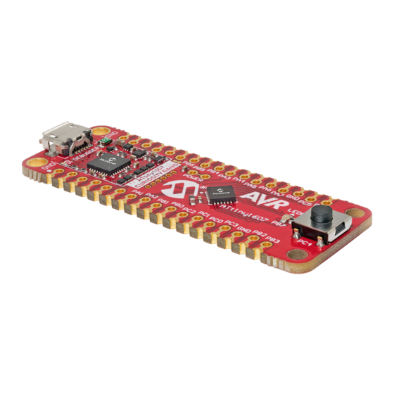
– 1.8-5.1V output voltage (limited by USB input voltage) – 500 mA maximum output current (limited by ambient temperature and output voltage) Board Overview The Microchip ATtiny1607 Curiosity Nano evaluation kit is a hardware platform to evaluate the ATtiny1607 microcontroller. Figure 1-1. ATtiny1607 Curiosity Nano Board Overview AT�ny1607... -
Page 5: Getting Started
Tip: If closed, the Kit Window in MPLAB X IDE can be reopened through the menu bar Window > Kit Window. Design Documentation and Relevant Links The following list contains links to the most relevant documents and software for the ATtiny1607 Curiosity Nano board: ® ®... - Page 6 Microchip development boards, ready to be adapted and extended. • ATtiny1607 Curiosity Nano website - Kit information, latest user guide, and design documentation. • ATtiny1607 Curiosity Nano on microchipDIRECT - Purchase this kit on microchipDIRECT. User Guide DS50002897C-page 6 ©...
-
Page 7: Curiosity Nano
A Data Gateway Interface (DGI) for code instrumentation with logic analyzer channels (debug GPIO) to visualize program flow The on-board debugger controls a Power and Status LED (marked PS) on the ATtiny1607 Curiosity Nano board. The table below shows how the LED is controlled in different operation modes. - Page 8 ATtiny1607 Curiosity Nano Curiosity Nano Remember: Keep the debugger’s firmware up-to-date. Firmware upgrades automatically when using ® MPLAB X IDE or Microchip Studio. 3.1.2 Virtual Serial Port (CDC) The virtual serial port (CDC) is a general purpose serial bridge between a host PC and a target device.
- Page 9 ATtiny1607 Curiosity Nano Curiosity Nano Info: For all operating systems: Be sure to use a terminal emulator that supports DTR signaling. See 3.1.2.4 Signaling. 3.1.2.3 Limitations Not all UART features are implemented in the on-board debugger CDC. The constraints are outlined here: •...
- Page 10 ATtiny1607 Curiosity Nano Curiosity Nano 3.1.2.5 Advanced Use CDC Override Mode In normal operation, the on-board debugger is a true UART bridge between the host and the device. However, in certain use cases, the on-board debugger can override the basic operating mode and use the CDC TX and RX pins for other purposes.
- Page 11 ATtiny1607 Curiosity Nano Curiosity Nano ® • Write access for programming Intel HEX formatted files into the target device’s memory • Write access for simple text files for utility purposes 3.1.3.1 Mass Storage Device Implementation The on-board debugger implements a highly optimized variant of the FAT12 file system that has several limitations, partly due to the nature of FAT12 itself and optimizations made to fulfill its purpose for its embedded application.
- Page 12 X IDE or a stand-alone application that can be used ® in parallel with MPLAB X IDE or Microchip Studio. Although DGI encompasses several physical data interfaces, the ATtiny1607 Curiosity Nano implementation includes logic analyzer channels: • Two debug GPIO channels (also known as DGI GPIO) 3.1.4.1...
-
Page 13: Curiosity Nano Standard Pinout
ATtiny1607 Curiosity Nano Curiosity Nano ® Figure 3-2. Monitoring Debug GPIO with MPLAB Data Visualizer Debug GPIO channels are timestamped, so the resolution of DGI GPIO events is determined by the resolution of the DGI timestamp module. Important: Although bursts of higher-frequency signals can be captured, the useful frequency range of signals for which debug GPIO can be used is up to about 2 kHz. -
Page 14: Power Supply
ATtiny1607 Curiosity Nano Curiosity Nano ...continued Debugger Signal Target MCU Description VBUS — VBUS voltage for external use VOFF — Voltage Off input. Disables the target regulator and target voltage when pulled low. — Target voltage — Common ground Figure 3-3. Curiosity Nano Standard Pinout... - Page 15 ATtiny1607 microcontroller. The voltage limits configured in the on-board debugger on ATtiny1607 Curiosity Nano are 1.8-5.5V. Info: The target voltage is set to 3.3V when the board is manufactured. It can be changed through ®...
- Page 16 VBUS Output Pin ATtiny1607 Curiosity Nano has a VBUS output pin that can be used to power external components that need a 5V supply. The VBUS output pin has a PTC fuse to protect the USB against short circuits. A side effect of the PTC fuse is a voltage drop on the VBUS output with higher current loads.
- Page 17 ATtiny1607 Curiosity Nano Curiosity Nano Figure 3-6. VBUS Output Voltage vs. Current 3.3.4 Power Supply Exceptions This is a summary of most exceptions that can occur with the power supply. Target Voltage Shuts Down This can happen if the target section draws too much current at a given voltage and cause the thermal shutdown safety feature of the MIC5353 regulator to kick in.
-
Page 18: Low-Power Measurement
ATtiny1607 Curiosity Nano Curiosity Nano No Target Voltage and PS LED is Lit 1 This occurs if the target voltage is set to 0.0V. To fix this, set the target voltage to a value within the specified voltage range for the target device. -
Page 19: Programming External Microcontrollers
7.4 Disconnecting the On-Board Debugger. Programming External Microcontrollers The on-board debugger on ATtiny1607 Curiosity Nano can be used to program and debug microcontrollers on external hardware. 3.5.1 Supported Devices All external AVR microcontrollers with the UPDI interface can be programmed and debugged with the on-board debugger with Microchip Studio. - Page 20 ATtiny1607 Curiosity Nano Curiosity Nano Figure 3-8. Hide Unsupported Devices Info: Microchip Studio allows any microcontroller and interface to be selected when the Hide unsupported devices setting is set to False, also microcontrollers and interfaces which are not supported by the on-board debugger.
- Page 21 ATtiny1607 Curiosity Nano Curiosity Nano Figure 3-9. Programming and Debugging Connections to Debugger GPIO straps (bottom side) Info: Cutting the connections to the debugger will disable programming, debugging, and data streaming from the ATtiny1607 mounted on the board. Tip: Solder 0Ω resistors across the footprints or short-circuit them with solder to reconnect the signals between the on-board debugger and the ATtiny1607.
-
Page 22: Connecting External Debuggers
ATtiny1607 Curiosity Nano Curiosity Nano Figure 3-10. Curiosity Nano Standard Pinout PS LED VBUS VOFF CDC RX DBG3 DEBUGGER CDC TX DBG0 DBG1 DBG2 CURIOSITY NANO Table 3-4. Programming and Debugging Interfaces ™ Curiosity Nano Pin UPDI ICSP DBG0 UPDI DATA SWDIO DBG1 —... - Page 23 ATtiny1607 Curiosity Nano Curiosity Nano ™ ® Figure 3-11. Connecting the MPLAB PICkit 4 In-Circuit Debugger/Programmer to ATtiny1607 Curiosity Nano 1 = Unused MPLAB® PICkit™ 4 2 = VDD 3 = Ground 4 = PGD 5 = Unused 6 = Unused...
- Page 24 ATtiny1607 Curiosity Nano Curiosity Nano Figure 3-12. Connecting the Atmel-ICE to ATtiny1607 Curiosity Nano AVR® Atmel-ICE Ground 1 = Unused 6 = Unused 7 = Unused 2 = GND 3 = UPDI 8 = Unused 4 = VTG 9 = Unused...
-
Page 25: Hardware User Guide
Using Pin-Headers The edge connector footprint on ATtiny1607 Curiosity Nano has a staggered design where each hole is shifted 8 mil (~0.2 mm) off-center. The hole shift allows the use of regular 100 mil pin-headers on the board without soldering. -
Page 26: Peripherals
PCB. Peripherals 4.2.1 There is one yellow user LED available on the ATtiny1607 Curiosity Nano board that can be controlled by either GPIO or PWM. Driving the connected I/O line to GND can also activate the LED. Table 4-1. LED Connection... - Page 27 4.2.3 On-Board Debugger Implementation ATtiny1607 Curiosity Nano features an on-board debugger that can be used to program and debug the ATtiny1607 using UPDI. The on-board debugger also includes a virtual serial port (CDC) interface over UART and debug GPIO. ®...
-
Page 28: Hardware Revision History And Known Issues
Identifying Product ID and Revision There are two ways to find the revision and product identifier of the ATtiny1607 Curiosity Nano: Either by utilizing the ® MPLAB X IDE or Microchip Studio Kit Window or by looking at the sticker on the bottom side of the PCB. - Page 29 Revision 1 does not have the Target Power strap described in 3.4 Low-Power Measurement. Instead, the current can be measured across the Power Supply strap, as described in 3.5 Programming External Microcontrollers. Figure 5-1. ATtiny1607 Curiosity Nano Revision 1 User Guide DS50002897C-page 29 © 2020 Microchip Technology Inc.
-
Page 30: Document Revision History
ATtiny1607 Curiosity Nano Document Revision History Document Revision History Doc. rev. Date Comment 12/2020 Updated overview, target schematic, and appendix pinout images. 11/2019 Updated kit images 06/2019 Initial document release User Guide DS50002897C-page 30 © 2020 Microchip Technology Inc. -
Page 31: Appendix
ATtiny1607 Curiosity Nano Appendix Appendix Schematic Figure 7-1. ATtiny1607 Curiosity Nano Schematic User Guide DS50002897C-page 31 © 2020 Microchip Technology Inc. - Page 32 ATtiny1607 Curiosity Nano Appendix User Guide DS50002897C-page 32 © 2020 Microchip Technology Inc.
-
Page 33: Assembly Drawing
ATtiny1607 Curiosity Nano Appendix Assembly Drawing Figure 7-2. ATtiny1607 Curiosity Nano Assembly Drawing Top Figure 7-3. ATtiny1607 Curiosity Nano Assembly Drawing Bottom User Guide DS50002897C-page 33 © 2020 Microchip Technology Inc. -
Page 34: Curiosity Nano Base For Click Boards
ATtiny1607 Curiosity Nano Appendix ™ Curiosity Nano Base for Click boards Figure 7-4. ATtiny1607 Curiosity Nano Pinout Mapping VBUS DBG3 VOFF DBG0 CDC TX DBG2 CDC RX DBG1 User Guide DS50002897C-page 34 © 2020 Microchip Technology Inc. -
Page 35: Disconnecting The On-Board Debugger
ATtiny1607 Curiosity Nano Appendix Disconnecting the On-Board Debugger The on-board debugger and level shifters can be completely disconnected from the ATtiny1607. The block diagram below shows all connections between the debugger and the ATtiny1607. The rounded boxes represent connections to the board edge. The signal names shown are also printed in silkscreen on the bottom side of the board. -
Page 36: Getting Started With Iar
GCC. Programming and ™ debugging of ATtiny1607 Curiosity Nano is supported in IAR Embedded Workbench for AVR using the Atmel-ICE interface. Some initial settings must be set up in the project to get the programming and debugging to work. - Page 37 ATtiny1607 Curiosity Nano Appendix Figure 7-7. Select Target Device Figure 7-8. Select Debugger User Guide DS50002897C-page 37 © 2020 Microchip Technology Inc.
- Page 38 ATtiny1607 Curiosity Nano Appendix Figure 7-9. Configure Interface User Guide DS50002897C-page 38 © 2020 Microchip Technology Inc.
-
Page 39: The Microchip Website
ATtiny1607 Curiosity Nano The Microchip Website Microchip provides online support via our website at www.microchip.com/. This website is used to make files and information easily available to customers. Some of the content available includes: • Product Support – Data sheets and errata, application notes and sample programs, design resources, user’s guides and hardware support documents, latest software releases and archived software •... -
Page 40: Legal Notice
The Adaptec logo, Frequency on Demand, Silicon Storage Technology, and Symmcom are registered trademarks of Microchip Technology Inc. in other countries. GestIC is a registered trademark of Microchip Technology Germany II GmbH & Co. KG, a subsidiary of Microchip Technology Inc., in other countries. -
Page 41: Quality Management System
ATtiny1607 Curiosity Nano Quality Management System For information regarding Microchip’s Quality Management Systems, please visit www.microchip.com/quality. User Guide DS50002897C-page 41 © 2020 Microchip Technology Inc. - Page 42 New York, NY Tel: 46-31-704-60-40 Tel: 631-435-6000 Sweden - Stockholm San Jose, CA Tel: 46-8-5090-4654 Tel: 408-735-9110 UK - Wokingham Tel: 408-436-4270 Tel: 44-118-921-5800 Canada - Toronto Fax: 44-118-921-5820 Tel: 905-695-1980 Fax: 905-695-2078 User Guide DS50002897C-page 42 © 2020 Microchip Technology Inc.
Need help?
Do you have a question about the ATtiny1607 Curiosity Nano and is the answer not in the manual?
Questions and answers