Table of Contents
Advertisement
Quick Links
ATmega4809 Curiosity Nano
ATmega4809 Curiosity Nano Hardware User Guide
Preface
The ATmega4809 Curiosity Nano evaluation kit is a hardware platform to evaluate the ATmega4809
microcontroller.
®
Supported by the Atmel Studio/Microchip MPLAB
X integrated development platform, the kit provides
easy access to the features of the ATmega4809 and explains how to integrate the device into a custom
design.
The Curiosity Nano series of evaluation kits include an onboard debugger, and no external tools are
necessary to program the ATmega4809.
User Guide
DS50002804A-page 1
©
2018 Microchip Technology Inc.
Advertisement
Table of Contents

Related Manuals for Microchip Technology ATmega4809 Curiosity Nano


Summary of Contents for Microchip Technology ATmega4809 Curiosity Nano
-
Page 1: Preface
ATmega4809 Curiosity Nano ATmega4809 Curiosity Nano Hardware User Guide Preface The ATmega4809 Curiosity Nano evaluation kit is a hardware platform to evaluate the ATmega4809 microcontroller. ® Supported by the Atmel Studio/Microchip MPLAB X integrated development platform, the kit provides easy access to the features of the ATmega4809 and explains how to integrate the device into a custom design. -
Page 2: Table Of Contents
3.3.2. External Supply......................11 3.4. Disconnecting the Onboard Debugger..................11 3.5. Current Measurement........................ 13 4. Hardware User Guide....................14 4.1. Connectors..........................14 4.1.1. ATmega4809 Curiosity Nano Pinout................14 4.2. Peripherals..........................15 4.2.1. LED..........................15 4.2.2. Mechanical Switch....................... 15 4.2.3. Crystal..........................15 4.3. Onboard Debugger Implementation................... 16 4.3.1. - Page 3 ATmega4809 Curiosity Nano Customer Support......................25 Microchip Devices Code Protection Feature..............25 Legal Notice........................26 Trademarks........................26 Quality Management System Certified by DNV.............27 Worldwide Sales and Service..................28 User Guide DS50002804A-page 3 © 2018 Microchip Technology Inc.
-
Page 4: Introduction
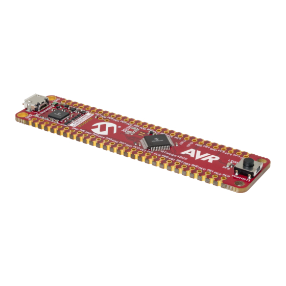
– 500 mA maximum output current (limited by ambient temperature and output voltage) Kit Overview The Microchip ATmega4809 Curiosity Nano evaluation kit is a hardware platform to evaluate the Microchip ATmega4809. Figure 1-1. ATmega4809 Curiosity Nano Evaluation Kit Overview Micro USB Power/Status 32.768 kHz... -
Page 5: Getting Started
Curiosity Nano and Xplained Pro boards and COM Ports. • ATmega4809 Curiosity Nano website - Kit information, latest user guide and design documentation. • ATmega4809 Curiosity Nano on Microchip Direct - Purchase this kit on Microchip Direct. User Guide DS50002804A-page 5 © 2018 Microchip Technology Inc. -
Page 6: Curiosity Nano
PC and a Data Gateway Interface (DGI) GPIO. Onboard Debugger ATmega4809 Curiosity Nano contains an onboard debugger for programming and debugging. The onboard debugger is a composite USB device of several interfaces: a debugger, a mass storage device, a data gateway, and a Virtual COM port (CDC). - Page 7 ATmega4809 Curiosity Nano Curiosity Nano On Windows machines, the CDC will enumerate as Curiosity Virtual COM Port and appear in the Ports section of the device manager. The COM port number is usually shown here. Info: On older Windows systems a USB driver is required for CDC. This driver is included in Atmel Studio and MPLAB X installations.
-
Page 8: Mass Storage Disk
ATmega4809 Curiosity Nano Curiosity Nano frames, not bytes. A maximum of 4 x 64-byte frames can be active at any time, the debugger will throttle the incoming frames accordingly. Sending full 64-byte frames containing data is the most efficient. When receiving data from the target, the debugger will queue up incoming bytes into 64-byte frames, which are sent to the USB queue for transmission to the host when they are full. -
Page 9: Curiosity Nano Standard Pinout
ATmega4809 Curiosity Nano Curiosity Nano 3.1.2.2 Configuration Words/Fuse Bytes ® Fuse Bytes (AVR Targets) The debugger does not mask any fuse bits or combinations when writing fuses. It is not possible to disable UPDI by fuse setting on devices with a dedicated UPDI pin. For devices with a shared/... -
Page 10: Power Supply
The voltage from the USB connector can vary between 4.4V to 5.25V (according to the USB specification) and will limit the maximum voltage to the target. The figure below shows the entire power supply system on ATmega4809 Curiosity Nano. Figure 3-2. Power Supply Block Diagram 3.3.1... -
Page 11: External Supply
3.3.2 External Supply ATmega4809 Curiosity Nano can be powered by an external voltage instead of the onboard target regulator. When the Voltage Off (VOFF) pin is shorted to ground (GND) the onboard debugger firmware disables the target regulator and it is safe to apply an external voltage to the VTG pin. - Page 12 ATmega4809 Curiosity Nano Curiosity Nano Figure 3-4. Onboard Debugger Connections to the ATmega4809 VBUS VOFF VCC_LEVEL VCC_TARGET VBUS VCC_P3V3 CUT STRAPS PA04/PA06 DBG0 PA07 DBG1 PA08 DBG2 PA16 DBG3 Level-Shift TARGET PA00 CDC TX PA01 CDC RX DIR x 5...
-
Page 13: Current Measurement
ATmega4809 Curiosity Nano Curiosity Nano Figure 3-5. Kit Modifications GPIO straps (bottom side) VTG strap (top side) Current Measurement The power to the ATmega4809 is connected from the onboard power supply to the target voltage supply (VTG) with a cut strap as shown in Section 3.4 Disconnecting the Onboard... -
Page 14: Hardware User Guide
PF0 and PF1 are connected to the onboard crystal and not connected to the edge connector by default. See Section 4.2.3 Crystal for more information. Figure 4-1. ATmega4809 Curiosity Nano Pinout Analog Peripheral Debug Port... -
Page 15: Peripherals
Peripherals 4.2.1 There is one yellow user LED available on the ATmega4809 Curiosity Nano kit that can be controlled by either GPIO or PWM. The LED can be activated by driving the connected I/O line to GND. Table 4-1. LED Connection... -
Page 16: Onboard Debugger Implementation
Edge connector Figure 4-2. GPIO Connection Footprint Onboard Debugger Implementation ATmega4809 Curiosity Nano features an onboard debugger that can be used to program and debug the ATmega4809 using UPDI. The onboard debugger also includes a Virtual Com port interface over UART ®... -
Page 17: Hardware Revision History
The serial number string has the following format: "nnnnrrssssssssss" n = product identifier r = revision s = serial number The product identifier for ATmega4809 Curiosity Nano is A09-3094. Revision 5 Revision 5 is the initially released revision. User Guide DS50002804A-page 17 ©... -
Page 18: Document Revision History
ATmega4809 Curiosity Nano Document Revision History Document Revision History Doc. rev. Date Comment 10/2018 Initial document release. User Guide DS50002804A-page 18 © 2018 Microchip Technology Inc. -
Page 19: Appendix
ATmega4809 Curiosity Nano Appendix Appendix Schematic Figure 7-1. ATmega4809 Curiosity Nano Schematic User Guide DS50002804A-page 19 © 2018 Microchip Technology Inc. - Page 20 ATmega4809 Curiosity Nano Appendix User Guide DS50002804A-page 20 © 2018 Microchip Technology Inc.
-
Page 21: Connecting External Debuggers
Even though there is an onboard debugger, external debuggers can be connected directly to ATmega4809 Curiosity Nano to program/debug the ATmega4809. The onboard debugger keeps all the pins connected to the ATmega4809 and board edge in tri-state when not actively used. Therefore, the onboard debugger will not interfere with any external debug tools. -
Page 22: Getting Started With Iar
™ GCC. Programming and debugging of ATmega4809 Curiosity Nano is supported in IAR Embedded Workbench for AVR using the Atmel-ICE interface. Some initial settings must be set up in the project to get the programming and debugging to work. - Page 23 ATmega4809 Curiosity Nano Appendix In the category Debugger > Atmel-ICE, select the Atmel-ICE 1 tab. Select UPDI as the interface and, optionally, select the UPDI frequency. Info: If the selection of Debug Port, mentioned in step 4, is grayed out, the interface is preselected, and the user can skip this configuration step.
- Page 24 ATmega4809 Curiosity Nano Appendix Figure 7-5. Select Debugger Figure 7-6. Configure Interface User Guide DS50002804A-page 24 © 2018 Microchip Technology Inc.
-
Page 25: The Microchip Web Site
ATmega4809 Curiosity Nano The Microchip Web Site Microchip provides online support via our web site at http://www.microchip.com/. This web site is used as a means to make files and information easily available to customers. Accessible by using your favorite Internet browser, the web site contains the following information: •... -
Page 26: Legal Notice
SQTP is a service mark of Microchip Technology Incorporated in the U.S.A. Silicon Storage Technology is a registered trademark of Microchip Technology Inc. in other countries. GestIC is a registered trademark of Microchip Technology Germany II GmbH & Co. KG, a subsidiary of Microchip Technology Inc., in other countries. -
Page 27: Quality Management System Certified By Dnv
ATmega4809 Curiosity Nano © 2018, Microchip Technology Incorporated, Printed in the U.S.A., All Rights Reserved. ISBN: 978-1-5224-3628-7 Quality Management System Certified by DNV ISO/TS 16949 Microchip received ISO/TS-16949:2009 certification for its worldwide headquarters, design and wafer fabrication facilities in Chandler and Tempe, Arizona; Gresham, Oregon and design centers in California ®... -
Page 28: Worldwide Sales And Service
New York, NY Sweden - Stockholm Tel: 631-435-6000 Tel: 46-8-5090-4654 San Jose, CA UK - Wokingham Tel: 408-735-9110 Tel: 44-118-921-5800 Tel: 408-436-4270 Fax: 44-118-921-5820 Canada - Toronto Tel: 905-695-1980 Fax: 905-695-2078 User Guide DS50002804A-page 28 © 2018 Microchip Technology Inc.
Need help?
Do you have a question about the ATmega4809 Curiosity Nano and is the answer not in the manual?
Questions and answers