Table of Contents
Advertisement
Quick Links
Advertisement
Table of Contents

Related Manuals for Aerotech ATS3600


Summary of Contents for Aerotech ATS3600
-
Page 1: Ats3600 Hardware Manual
ATS3600 Hardware Manual Revision: 1.00.00... - Page 2 This manual contains proprietary information and may not be reproduced, disclosed, or used in whole or in part without the express written permission of Aerotech, Inc. Product names mentioned herein are used for identification purposes only and may be trademarks of their respective companies.
-
Page 3: Table Of Contents
ATS3600 Hardware Manual Table of Contents Table of Contents ATS3600 Hardware Manual Table of Contents List of Figures List of Tables Safety Procedures and Warnings EU Declaration of Incorporation Chapter 1: Overview 1.1. Environmental Specifications 1.2. Accuracy and Temperature Effects 1.3. -
Page 4: List Of Figures
Table of Contents ATS3600 Hardware Manual List of Figures Figure 2-1: ATS3600 Dimensions Figure 3-1: Brushless Motor and Feedback Wiring [-M1 and -M2] Figure 3-2: Stepper Motor and Feedback Wiring [-M3] Figure 3-3: Machine Direction Figure 3-4: Hall Phasing Figure 3-5:... -
Page 5: List Of Tables
ATS3600 Hardware Manual Table of Contents List of Tables Table 1-1: ATS3600 Model Numbering System Table 1-2: Environmental Specifications Table 1-3: ATS3600 Series Specifications Table 2-1: Stage to Mounting Surface Hardware Table 3-1: Brushless Motor Connector Pinout [-M1 and -M2]... -
Page 6: Safety Procedures And Warnings
D A N G E R : This product contains potentially lethal voltages. To reduce the possibility of electrical shock, bodily injury, or death the following precautions must be followed. 1. Access to the ATS3600 and component parts must be restricted while connected to a power source. -
Page 7: Eu Declaration Of Incorporation
ATS3600 Hardware Manual Table of Contents EU Declaration of Incorporation Manufacturer: Aerotech, Inc. 101 Zeta Drive Pittsburgh, PA 15238-2811 herewith declares that the product: ATS3600 Stage is intended to be incorporated into machinery to constitute machinery covered by the Directive 2006/42/EC as amended;... - Page 8 Table of Contents ATS3600 Hardware Manual This page intentionally left blank. www.aerotech.com...
-
Page 9: Chapter 1: Overview
Overview Chapter 1: Overview N O T E : Aerotech continually improves its product offerings; listed options may be superseded at any time. All drawings and illustrations are for reference only and were complete and accurate as of this manual’s release. Refer to www.aerotech.com for the most up-to-date information. -
Page 10: Environmental Specifications
Aerotech products are designed for and built in a 20°C (68°F) environment. Extreme temperature changes could cause a decrease in performance or permanent damage to the ATS3600. At a minimum, the environmental temperature must be controlled to within 0.25ºC per 24 hours to ensure the ATS3600 specifications are repeatable over an extended period of time. -
Page 11: Basic Specifications
Overview 1.3. Basic Specifications N O T E : Aerotech continually improves its product offerings; listed options may be superseded at any time. All drawings and illustrations are for reference only and were complete and accurate as of this manual’s release. Refer to www.aerotech.com for the most up-to-date information. -
Page 12: Vacuum Operation
To make sure that the ATS3600 will continue to perform well in the vacuum environment, use the guidelines that follow (in addition to standard handling, installation, and lubrication guidelines outlined in this manual). -
Page 13: Chapter 2: Mechanical Specifications And Installation
Mechanical Specifications and Installation Chapter 2: Mechanical Specifications and Installation W A R N I N G : ATS3600 installation must be in accordance to instructions provided by this manual and any accompanying documentation. Failure to follow these instructions could result in injury or damage to the equipment. -
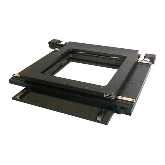
Page 14: Dimensions
ATS3600 Hardware Manual 2.2. Dimensions N O T E : Aerotech continually improves its product offerings; listed options may be superseded at any time. All drawings and illustrations are for reference only and were complete and accurate as of this manual’s release. -
Page 15: Securing The Stage To The Mounting Surface
N O T E : The stage table may offer a considerable amount of resistance when it is moved manually. This is especially true if the stage is fitted with a motor assembly. W A R N I N G : Do not attempt to manually move the ATS3600 if it is connected to a power source. -
Page 16: Attaching The Payload To The Stage
Aerotech recommends that customers use a representative payload during start-up to prevent accidental damage to the stage and the payload. Proceed with the electrical installation and test the motion control system in accordance with the system documentation. -
Page 17: Chapter 3: Electrical Specifications And Installation
Failure to do so may expose the operator to electric shock and mechanical hazards. N O T E : If the ATS3600 was not purchased as part of an integrated system, refer to the controller documentation to adjust servo gains for optimum velocity and position stability. -
Page 18: Motor And Feedback Connectors
Stages equipped with standard motors and encoders come from the factory completely wired and assembled. N O T E : Refer to the other documentation accompanying your Aerotech equipment. Call your Aerotech representative if there are any questions on system configuration. -
Page 19: Table 3-1: Brushless Motor Connector Pinout [-M1 And -M2]
ATS3600 Hardware Manual Electrical Specifications and Installation Table 3-1: Brushless Motor Connector Pinout [-M1 and -M2] Description Connector Case Shield Connection Motor Phase A Motor Phase B Motor Phase C Reserved Reserved Reserved Reserved Reserved Frame Ground (motor protective ground) -
Page 20: Table 3-3: Brushless Motor Feedback Connector Pinout [-M1 And -M2]
Electrical Specifications and Installation ATS3600 Hardware Manual Table 3-3: Brushless Motor Feedback Connector Pinout [-M1 and -M2] Description Connector Case Shield Connection Reserved Over-Temperature Thermistor sensor +5 V power supply Reserved Hall Effect sensor, phase B Marker-N Marker Reserved Reserved Hall Effect sensor, phase A... -
Page 21: Table 3-4: Stepper Motor Feedback Connector Pinout [-M3]
ATS3600 Hardware Manual Electrical Specifications and Installation Table 3-4: Stepper Motor Feedback Connector Pinout [-M3] Description Connector Reserved Reserved +5 V power supply Reserved Reserved Marker-N Marker Reserved Reserved Reserved Reserved Reserved Reserved Cosine Cosine-N +5 V power supply Sine... -
Page 22: Table 3-5: Limits With 9-Pin D-Connector (-Li1 Or -Li3)
Electrical Specifications and Installation ATS3600 Hardware Manual Table 3-5: Limits with 9-Pin D-Connector (-LI1 or -LI3) Pin # Description Connector Case Signal shield connection +5V supply input for optical limit switch boards Common ground to limit switch Signal indicating maximum travel produced by positive/CW stage direction... -
Page 23: Table 3-7: 15-Pin Linear Encoder Connector (-E1)
ATS3600 Hardware Manual Electrical Specifications and Installation Table 3-7: 15-Pin Linear Encoder Connector (-E1) -E1 Option Connector Sine Cosine Marker +5 V power supply Reserved Reserved Reserved Reserved Sine-N Cosine-N Marker-N Common ground Setup Reserved Reserved Table 3-8: 15-Pin Linear Encoder Connector (-E2) -
Page 24: Motor And Feedback Wiring
Electrical Specifications and Installation ATS3600 Hardware Manual 3.2. Motor and Feedback Wiring All motor and controller manufacturers have their own designations for motor phases A/B/C and Hall signals A/B/C (refer to Section 3.5. for motor phasing). Shielded cables are required for the motor and feedback connections. -
Page 25: Figure 3-2: Stepper Motor And Feedback Wiring [-M3]
ATS3600 Hardware Manual Electrical Specifications and Installation Figure 3-2: Stepper Motor and Feedback Wiring [-M3] www.aerotech.com Chapter 3... -
Page 26: Motor And Feedback Specifications
High impedance (Logic "1") when not in limit Requires external pull-up to +5 V (10 kΩ recommended) Note: If the ATS3600 is driven beyond the electrical limit, it will encounter a mechanical stop. Impacting the mechanical stop could cause damage to the stage even at low speeds. -
Page 27: Table 3-10: Motor Specifications [Bms60]
5. All performance and electrical specifications ±10% 6. Maximum winding temperature is 100 °C (thermistor trips at 100 °C) 7. Ambient operating temperature range 0 °C - 25 °C; consult Aerotech for performance in elevated ambient temperatures 8. All Aerotech amplifiers are rated A ;... -
Page 28: Table 3-11: Motor Specifications [Sm60]
Electrical Specifications and Installation ATS3600 Hardware Manual Table 3-11: Motor Specifications [SM60] SM60-VT2 NEMA Motor Frame Size NEMA 23 Stall Torque 1.41 N·m (200 oz·in) Rated Amps Per Phase 0.84 A Maximum Voltage Across the Motor 160 V 3.00E-05 kg·m Rotor Inertia (0.0042 oz·in·s... -
Page 29: Limits, Marker, And Machine Direction
Electrical Specifications and Installation 3.4. Limits, Marker, and Machine Direction Aerotech stages are configured to have positive and negative "machine" directions. The machine direction defines the phasing of the feedback and motor signals and is dictated by the stage wiring (refer to Section 3.5. -
Page 30: Motor And Feedback Phasing
Electrical Specifications and Installation ATS3600 Hardware Manual 3.5. Motor and Feedback Phasing Motor phase voltage is measured relative to the virtual wye common point. Figure 3-4: Hall Phasing Figure 3-5: Analog Encoder Phasing Reference Diagram Figure 3-6: TTL Encoder Phasing Reference Diagram Chapter 3 www.aerotech.com... -
Page 31: Chapter 4: Maintenance
4.1. Service and Inspection Schedule Inspect the ATS3600 at least once per month. A longer or shorter inspection interval may be required depending on the application and conditions, such as the duty cycle, speed, and environment. -
Page 32: Cleaning And Lubrication
When cleaning and/or lubricating components of the ATS3600 series stages: 1. Be sure to use a clean, dry, soft, lint-free cloth for cleaning. 2. Before using a cleaning solvent on any part of the ATS3600, blow away small particles and dust with clean, dry, compressed air. - Page 33 ATS3600 Hardware Manual Maintenance 4. Remove any dirty or dried lubricant from the ball screw. Use a clean, lint-free cloth with a side-to- side motion. Manually turn the ball screw to clean its entire circumference. A swab soaked in isopropyl alcohol may be used to remove stubborn debris.
-
Page 34: Troubleshooting
Maintenance ATS3600 Hardware Manual 4.3. Troubleshooting Symptom Possible Cause and Solution Brake not released (if equipped with brake; refer to stage documentation). In Limit condition. Check limits (refer to Chapter 3) and refer to the Controller Stage will not move documentation for polarity and compatibility requirements (Example: voltage requirements). -
Page 35: Appendix A: Warranty And Field Service
Aerotech makes no warranty that its products are fit for the use or purpose to which they may be put by the buyer, whether or not such use or purpose has been disclosed to Aerotech in specifications or drawings previously or subsequently provided, or whether or not Aerotech’s... - Page 36 Aerotech's approval. On-site Warranty Repair If an Aerotech product cannot be made functional by telephone assistance or by sending and having the customer install replacement parts, and cannot be returned to the Aerotech service center for repair, and if Aerotech determines the problem could be warranty-related, then the following policy applies:...
-
Page 37: Appendix B: Revision History
ATS3600 Hardware Manual Revision History Appendix B: Revision History Revision Description 1.00.00 New Manual www.aerotech.com Appendix B... - Page 38 Revision History ATS3600 Hardware Manual This page intentionally left blank. Appendix B www.aerotech.com...
-
Page 39: Index
ATS3600 Hardware Manual Index Index label Limit Switch Specifications 2006/42/EC linear motion guide lubrication acetone (caution) lubricants Altitude vacuum operation Ambient Temperature Lubrication BMS60 mounting surface Braycote® 602EF cleaning securing stage cleaning multiaxis combinations mounting surface Cleaning part number cleaning solvent... - Page 40 Index ATS3600 Hardware Manual vacuum vacuum guidelines Vibration Warranty and Field Service Index www.aerotech.com...
Need help?
Do you have a question about the ATS3600 and is the answer not in the manual?
Questions and answers