Table of Contents
Advertisement
Quick Links
Advertisement
Table of Contents

Related Manuals for Aerotech AXR Series


Summary of Contents for Aerotech AXR Series
-
Page 1: Axr Hardware Manual
AXR Hardware Manual Revision: 1.03.00... - Page 2 This manual contains proprietary information and may not be reproduced, disclosed, or used in whole or in part without the express written permission of Aerotech, Inc. Product names mentioned herein are used for identification purposes only and may be trademarks of their respective companies.
-
Page 3: Table Of Contents
3.3. Motor and Feedback Specifications 3.4. Limits, Marker, and Machine Direction 3.5. Motor and Feedback Phasing Chapter 4: Maintenance 4.1. Service and Inspection Schedule 4.2. Cleaning and Lubrication 4.3. Troubleshooting Appendix A: Warranty and Field Service Appendix B: Revision History Index www.aerotech.com... -
Page 4: List Of Figures
Figure 2-21: AXR150G160-125C Balance Chart Figure 3-1: Electrical Connectors and Grounds Figure 3-2: Motor and Feedback Wiring Figure 3-3: Machine Direction Figure 3-4: Hall Phasing Figure 3-5: Analog Encoder Phasing Reference Diagram Figure 3-6: Encoder Phasing Reference Diagram (Standard) www.aerotech.com... -
Page 5: List Of Tables
Table of Contents List of Tables Table 1-1: Model Numbering System Table 1-2: Environmental Specifications Table 1-3: AXR Series Specifications Table 2-1: Stage to Mounting Surface Hardware Table 2-2: Clamping Ranges for Self Centering Scroll Chucks Table 2-3: Gear Drive Specifications... -
Page 6: Safety Procedures And Warnings
N O T E : Aerotech continually improves its product offerings; listed options may be superseded at any time. All drawings and illustrations are for reference only and were complete and accurate as of this manual’s release. -
Page 7: Eu Declaration Of Incorporation
AXR Hardware Manual Table of Contents EU Declaration of Incorporation Manufacturer: Aerotech, Inc. 101 Zeta Drive Pittsburgh, PA 15238-2811 herewith declares that the product: AXR Stage is intended to be incorporated into machinery to constitute machinery covered by the Directive 2006/42/EC as amended;... - Page 8 Table of Contents AXR Hardware Manual This page intentionally left blank. www.aerotech.com...
-
Page 9: Chapter 1: Overview
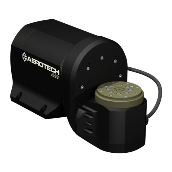
Overview Chapter 1: Overview Aerotech’s AXR integrated two-axis rotary assembly provides high-speed machining capabilities for complex 3D part geometries. The precision-aligned system allows accurate positioning on a hemispherical surface. Multiple frame sizes with direct- or gear-driven options provide a wide range of load carrying capability. -
Page 10: Table 1-1: Model Numbering System
Counterweight kit for AXR100 (-0E) for offset loads of 13.1 N·m 1. Offset loads include both the payload and stage unbalance. 2. A linear combination of counterweight kits can be employed to achieve balance. Refer to Section 0.0.1. determine if application falls within balance limits. Chapter 1 www.aerotech.com... -
Page 11: Environmental Specifications
Indoor use only 1.2. Accuracy and Temperature Effects Aerotech products are designed for and built in a 20°C (68°F) environment. Extreme temperature changes could cause a decrease in performance or permanent damage to the AXR. At a minimum, the environmental temperature must be controlled to within 0.25ºC per 24 hours to ensure the AXR specifications are... -
Page 12: Basic Specifications
AXR Hardware Manual 1.3. Basic Specifications N O T E : Aerotech continually improves its product offerings; listed options may be superseded at any time. All drawings and illustrations are for reference only and were complete and accurate as of this manual’s release. -
Page 13: Chapter 2: Installation
Aerotech. Use compressed nitrogen or clean, dry, oil-less air to remove any dust or debris that has collected during shipping. -
Page 14: Figure 2-1: Axr With Shipping Bracket
Assembly and Installation AXR Hardware Manual Figure 2-1: AXR With Shipping Bracket Chapter 2 www.aerotech.com... -
Page 15: Dimensions
AXR Hardware Manual Assembly and Installation 2.2. Dimensions Figure 2-2: AXR100D Dimensions www.aerotech.com Chapter 2... -
Page 16: Figure 2-3: Axr150 Dimensions
Assembly and Installation AXR Hardware Manual Figure 2-3: AXR150 Dimensions Chapter 2 www.aerotech.com... -
Page 17: Securing The Stage To The Mounting Surface
If machining is required to achieve the desired flatness, it should be performed on the mounting surface rather than the AXR. Shimming should be avoided if possible. If shimming is required, it should be minimized to retain maximum rigidity of the system. AXR series stages have a fixed mounting pattern (as shown in Figure 2-4). -
Page 18: Attaching The Payload To The Stage
Depending on the options of the unit, is possible that, before you can run the stage, you must install a payload to match the balancing of the system as it was shipped. Aerotech recommends starting the stage for the first time using a dummy payload attached that has the same mass and center of gravity as the final payload that is to be used with the system. -
Page 19: B Axis With Manual Three Jaw Chuck
34.8 to 73.9 71.9 to 115.1 Allowable clamping force varies with the structure of the payload. Be sure that the clamping force imparted on the workpiece is sufficient to hold the part in place before operating the stage. www.aerotech.com Chapter 2... -
Page 20: Air Line Access
2.5. Air Line Access AXR series stages are provided with a internal air line for a single pneumatic control signal up to the Yaw axis tabletop. Access to the air line is located in the rear of the Tilt axis as shown in Figure 2-6. -
Page 21: Brake Option
However, the gear drive is speed limited. See Table 2-3 for gear drive specifications. Table 2-3: Gear Drive Specifications Model Gear Ratio Max Speed Max Torque AXR150G50 51:1 10 rpm 305 N·m AXR150G100 101:1 5 rpm 605 N·m AXR150G160 161:3 3 rpm 964 N·m www.aerotech.com Chapter 2... -
Page 22: Counterbalance System
Assembly and Installation AXR Hardware Manual 2.8. Counterbalance System For applications requiring balancing, such as direct drive systems, Aerotech has designed a system of counterweights to allow maximum balance flexibility. Counterbalancing strategies depend on the type of mounting: Offset or Inline. -
Page 23: Inline Mounting Counterbalancing
By stacking the weights the payload can be balanced. Each supplied kit contains several weights so a wide range of payloads can be balanced. These kits also come in the form of counterweight sleeves or covers. Figure 2-9: Adjustable Counterweight Locations (-0E Option) www.aerotech.com Chapter 2... -
Page 24: Balancing Charts
Unshaded regions indicate that the application payload unbalance is too large for the particular configuration of AXR. In this case, Aerotech recommends choosing a different AXR configuration. Contact your Aerotech sales representative to determine which configuration will work best. -
Page 25: Figure 2-11: Axr100D-0E Balance Chart
AXR Hardware Manual Assembly and Installation Figure 2-11: AXR100D-0E Balance Chart Figure 2-12: AXR100D-100C Balance Chart www.aerotech.com Chapter 2... -
Page 26: Figure 2-13: Axr150D-125 Balance Chart
Assembly and Installation AXR Hardware Manual Figure 2-13: AXR150D-125 Balance Chart Figure 2-14: AXR150D-125C Balance Chart Chapter 2 www.aerotech.com... -
Page 27: Figure 2-15: Axr150D-0E Balance Chart
AXR Hardware Manual Assembly and Installation Figure 2-15: AXR150D-0E Balance Chart Figure 2-16: AXR150G50-125 Balance Chart www.aerotech.com Chapter 2... -
Page 28: Figure 2-17: Axr150G100-125 Balance Chart
Assembly and Installation AXR Hardware Manual Figure 2-17: AXR150G100-125 Balance Chart Figure 2-18: AXR150G160-125 Balance Chart Chapter 2 www.aerotech.com... -
Page 29: Figure 2-19: Axr150G50-125C Balance Chart
AXR Hardware Manual Assembly and Installation Figure 2-19: AXR150G50-125C Balance Chart Figure 2-20: AXR150G100-125C Balance Chart www.aerotech.com Chapter 2... -
Page 30: Figure 2-21: Axr150G160-125C Balance Chart
Assembly and Installation AXR Hardware Manual Figure 2-21: AXR150G160-125C Balance Chart Chapter 2 www.aerotech.com... -
Page 31: Balancing The A Axis
As a general rule, Aerotech recommends operating the system with the A axis balanced. If imbalance of the A axis is necessary, Aerotech recommends keeping the imbalance on the A axis less than 25 percent of the continuous torque rating of the A axis motor. These values are listed in Table 2-4. - Page 32 Assembly and Installation AXR Hardware Manual This page intentionally left blank. Chapter 2 www.aerotech.com...
-
Page 33: Chapter 3: Electrical Specifications And Installation
W A R N I N G : Electrical installation must be performed by properly qualified personnel. Aerotech motion control systems are adjusted at the factory for optimum performance. When the AXR is part of a complete Aerotech motion control system, setup usually involves connecting the AXR to the appropriate drive chassis with the cables provided. -
Page 34: Motor And Feedback Connectors
N O T E : Refer to the other documentation accompanying your Aerotech equipment. Call your Aerotech representative if there are any questions on system configuration. N O T E : If using standard Aerotech motors and cables, motor and encoder connection adjustments are not required. -
Page 35: Table 3-1: Motor Pin Assignments For The A And B Axes
Motor Phase A Motor Phase B Motor Phase C Reserved Reserved Reserved Reserved Reserved Frame ground (motor protective ground) Mating Connector Aerotech P/N Third Party P/N Backshell ECK00656 Amphenol #17E-1726-2 Sockets [QTY. 4] ECK00659 ITT Cannon #DM53744-6 Connector ECK00657 ITT Cannon #DBM9W4SA197 www.aerotech.com... -
Page 36: Table 3-2: Feedback Pin Assignments For The A Axis
Common ground (internally connected to Pin 21) Common ground (internally connected to Pin 20) Reserved Reserved Signal indicating maximum travel produced by negative/CCW stage direction Reserved Mating Connector Aerotech P/N Third Party P/N Backshell ECK00656 Amphenol #17E-1726-2 Connector ECK00300 FCI DB25S064TLF Chapter 3 www.aerotech.com... -
Page 37: Table 3-3: Feedback Pin Assignments For The B Axis
+5 V power supply (internally connected to Pin 3) Sine Sine-N Reserved Common ground (internally connected to Pin 21) Common ground (internally connected to Pin 20) Reserved Reserved Reserved Reserved Mating Connector Aerotech P/N Third Party P/N Backshell ECK00656 Amphenol #17E-1726-2 Connector ECK00300 FCI DB25S064TLF www.aerotech.com Chapter 3... -
Page 38: Motor And Feedback Wiring
All motor and controller manufacturers have their own designations for motor phases A/B/C and Hall signals A/B/C (refer to Section 3.5. for motor phasing). Shielded cables are required for the motor and feedback connections. Figure 3-2: Motor and Feedback Wiring Chapter 3 www.aerotech.com... -
Page 39: Motor And Feedback Specifications
Requires external pull-up to +5 V (10 kΩ recommended) Notes: If the AXR is driven beyond the electrical limit, it will encounter a mechanical stop. Impacting the mechanical stop could cause damage to the stage even at low speeds. www.aerotech.com Chapter 3... -
Page 40: Table 3-5: Encoder Specifications (Axr100D, Axr150D)
N O T E : The encoders used on all AXR series stages come standard with a MHz clock rate. Aerotech can provide slower or faster clock rates to match the controller being used. Consult Aerotech for more information. -
Page 41: Table 3-8: S-76-35 Motor Specifications (For The Axr100D)
6. Specifications given are for the motor only. When integrated into a housing with bearings additional losses should be considered. 7. Maximum winding temperature is 100 °C (thermistor trips at 100 °C) 8. Ambient operating temperature range 0 °C - 25 °C; consult Aerotech for performance in elevated ambient temperatures 9. All Aerotech amplifiers are rated A ;... -
Page 42: Table 3-9: S-130-Xx Motor Specifications (For The Axr100D, Axr150D, And Axr150G)
6. Specifications given are for the motor only. When integrated into a housing with bearings additional losses should be considered. 7. Maximum winding temperature is 100 °C (thermistor trips at 100 °C) 8. Ambient operating temperature range 0 °C - 25 °C; consult Aerotech for performance in elevated ambient temperatures 9. All Aerotech amplifiers are rated A ;... -
Page 43: Table 3-10: S-180-Xx Motor Specifications (For The Axr150D And Axr150G)
6. Specifications given are for the motor only. When integrated into a housing with bearings additional losses should be considered. 7. Maximum winding temperature is 100 °C (thermistor trips at 100 °C) 8. Ambient operating temperature range 0 °C - 25 °C; consult Aerotech for performance in elevated ambient temperatures 9. All Aerotech amplifiers are rated A ;... -
Page 44: Limits, Marker, And Machine Direction
AXR Hardware Manual 3.4. Limits, Marker, and Machine Direction Aerotech stages are configured to have positive and negative "machine" directions. The machine direction defines the phasing of the feedback and motor signals and is dictated by the stage wiring (refer to Section 3.5. -
Page 45: Motor And Feedback Phasing
AXR Hardware Manual Electrical Specifications and Installation 3.5. Motor and Feedback Phasing Motor phase voltage is measured relative to the virtual wye common point. Figure 3-4: Hall Phasing www.aerotech.com Chapter 3... -
Page 46: Figure 3-5: Analog Encoder Phasing Reference Diagram
Electrical Specifications and Installation AXR Hardware Manual Figure 3-5: Analog Encoder Phasing Reference Diagram Figure 3-6: Encoder Phasing Reference Diagram (Standard) Chapter 3 www.aerotech.com... -
Page 47: Chapter 4: Maintenance
Maintenance Chapter 4: Maintenance The AXR series stages are designed to require minimum maintenance. There are some items that may require preventative maintenance during the lifetime of the stage. This chapter will cover information about component maintenance and replacement, intervals between lubrication, detail the lubrication and inspection process, and specify recommended lubricants and cleaning solvents. -
Page 48: Cleaning And Lubrication
There are no elements on AXR stages that require lubrication. If the application process uses only a small portion of travel for most of the duty cycle, periodically drive the stage through full travel to redistribute the lubrication in the bearings. Chapter 4 www.aerotech.com... -
Page 49: Troubleshooting
Encoder (sine and cosine) signal connections (refer to Chapter 3 Stage moves Controller documentation). uncontrollably Motor Connections (refer to Chapter 3 and the Controller documentation). Gains misadjusted (refer to the Controller documentation). Stage oscillates or squeals Encoder signals (refer to the Controller documentation). www.aerotech.com Chapter 4... - Page 50 Maintenance AXR Hardware Manual This page intentionally left blank. Chapter 4 www.aerotech.com...
-
Page 51: Appendix A: Warranty And Field Service
Aerotech makes no warranty that its products are fit for the use or purpose to which they may be put by the buyer, whether or not such use or purpose has been disclosed to Aerotech in specifications or drawings previously or subsequently provided, or whether or not Aerotech’s... - Page 52 Aerotech's approval. On-site Warranty Repair If an Aerotech product cannot be made functional by telephone assistance or by sending and having the customer install replacement parts, and cannot be returned to the Aerotech service center for repair, and if Aerotech determines the problem could be warranty-related, then the following policy applies:...
-
Page 53: Appendix B: Revision History
AXR Hardware Manual Revision History Appendix B: Revision History Revision General Information 1.03.00 Full Revision 1.02.00 Revision changes have been archived. If you need a copy of this revision, contact Aerotech 1.01.00 Global Technical Support. 1.00.00 www.aerotech.com Appendix B... - Page 54 Revision History AXR Hardware Manual This page intentionally left blank. Appendix B www.aerotech.com...
-
Page 55: Index
24,31 maintenance Brake Manual Three Jaw Chuck Motor Specifications cleaning AXR100D (A Axis) solvents AXR150D (A Axis) Cleaning AXR150D (B Axis) Counterbalancing AXR150G (A Axis) AXR150G (B Axis) Dimensions S-130-39 S-130-60 Electrical Installation S-180-44 Electrical Specifications S-180-69 S-130 www.aerotech.com Index... - Page 56 Protection Rating protective ground connection S-130 Electrical Specifications Performance Specifications S-180 Electrical Specifications Performance Specifications S-76 Electrical Specifications Performance Specifications Securing the Stage to the Mounting Surface serial number shimming solvents Specifications stabilizing stage stage distortion stabilizing Support Index www.aerotech.com...
Need help?
Do you have a question about the AXR Series and is the answer not in the manual?
Questions and answers