
Related Manuals for Aerotech ABL2000 Series


Summary of Contents for Aerotech ABL2000 Series
- Page 1 ABL2000 Series Stage User’s Manual P/N: EDS105 (Revision 1.02.00) Dedicated to the Science of Motion Aerotech, Inc. 101 Zeta Drive, Pittsburgh, PA, 15238 Phone: 412-963-7470 Fax: 412-963-7459 www.aerotech.com...
- Page 2 Email: saleschina@aerotech.com Revision History Revision 1.02.00 March 2, 2011 Revision 1.01.00 January 5, 2009 Revision 1.00.00 February 2, 2006 Product names mentioned herein are used for identification purposes only and may be trademarks of their respective companies. © Aerotech, Inc. 2011...
-
Page 3: Table Of Contents
ABL2000 Series Stage User's Manual Table of Contents Table of Contents Table of Contents List of Figures List of Tables Chapter 1: Overview 1.1. Standard Features 1.1.1. Optional Features 1.1.2. Cable Management Systems 1.2. Dimensions 1.3. Safety Procedures and Warnings 1.4. - Page 4 Table of Contents ABL2000 Series Stage User's Manual www.aerotech.com...
-
Page 5: List Of Figures
With Magnet Tracks Removed, Stage Mounting Holes are Accessible Figure 3-1: Velocity vs. resolution as a function of system data rate (ABL2000 with LTAS or LNAS encoder) Figure 3-2: Load capability of ABL2000 Series Stages Figure 3-3: Cantilever Length Diagram Figure 3-4: Maximum Accelerations Possible Based on Mass... - Page 6 List of Figures ABL2000 Series Stage User's Manual www.aerotech.com...
-
Page 7: List Of Tables
ABL2000 Series Stage User's Manual List of Tables List of Tables Table 1-1: Ordering Example (ABL20100-10-RIBBON-LN100AS-NC-XY-CMS) Table 1-2: Model Numbers and Ordering Options Table 3-1: Environmental Specifications Table 3-2: ABL2000 Series Specifications Table 3-3: ABL2000 Series Resolution Information Table 3-4:... - Page 8 List of Tables ABL2000 Series Stage User's Manual viii www.aerotech.com...
-
Page 9: Chapter 1: Overview
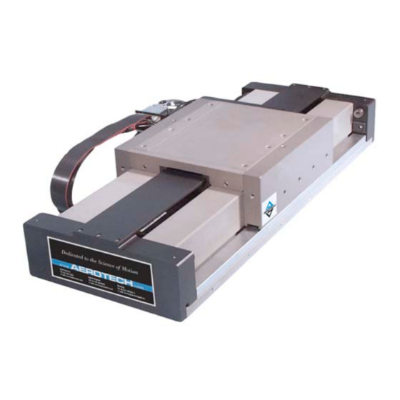
This manual describes Aerotech’s ABL2000 series of air bearing positioning stages. The ABL2000 series supports travel distances ranging from 100 mm to 1200 mm (4 in to 48 in). The ABL2000 combines excellent pitch/yaw characteristics with the unsurpassed velocity control that is necessary for print- ing, imaging, and fiber-optic applications. -
Page 10: Optional Features
Overview ABL2000 Series Stage User's Manual 1.1.1. Optional Features The ABL2000 can be readily customized to meet the needs of individual applications. Common examples include cable management for stage-mounted payloads, custom tabletops, and granite bases. Contact the Aerotech factory for more details. -
Page 11: Cable Management Systems
ABL2000 Series Stage User's Manual Overview Table 1-2: Model Numbers and Ordering Options (continued) High-Accuracy Linear Encoders -LN10AS High-accuracy linear encoder for ABL20010; amplified sine output -LN20AS High-accuracy linear encoder for ABL20020; amplified sine output -LN30AS High-accuracy linear encoder for ABL20030; amplified sine output -LN40AS High-accuracy linear encoder for ABL20040;... -
Page 12: Dimensions
Overview ABL2000 Series Stage User's Manual 1.2. Dimensions Figure 1-2: ABL2000 Dimensions Chapter 1 www.aerotech.com... -
Page 13: Safety Procedures And Warnings
ABL2000 Series Stage User's Manual Overview 1.3. Safety Procedures and Warnings The following statements apply throughout this manual. Failure to observe these precautions could result in serious injury to those performing the procedures and damage to the equipment. This manual and any additional instructions included with the stage should be retained for the lifetime of the stage. - Page 14 Overview ABL2000 Series Stage User's Manual Do not expose the stage to environments or conditions outside the specified range of oper- ating environments. Operation in conditions other than those specified can cause damage to the equipment. The stage must be mounted securely. Improper mounting can result in injury and damage to the equipment.
-
Page 15: Ec Declaration Of Incorporation
ABL2000 Series Stage User's Manual Overview 1.4. EC Declaration of Incorporation Manufactorer: Aerotech, Inc. 101 Zeta Drive Pittsburgh, PA 15238 herewith declares that the product: Aerotech, Inc. ABL2000 Stage is intended to be incorporated into machinery to constitute machinery covered by the Directive 2006/42/EC as amended;... - Page 16 Overview ABL2000 Series Stage User's Manual Chapter 1 www.aerotech.com...
-
Page 17: Chapter 2: Installation
ABL2000 Series Stage User's Manual Installation Chapter 2: Installation This chapter describes the installation procedure the ABL2000 stage, including handling the stage properly, securing the stage to the mounting surface, attaching the payload, and making the electrical connections. Installation must follow the instructions in this chapter. Failure to follow these instructions could result in injury and damage to the equipment. -
Page 18: Preparing The Mounting Surface
The mounting surface should be flat and have adequate stiffness in order to achieve the maximum per- formance from the ABL2000. When an ABL2000 series stage is mounted to a non-flat surface, the stage can be distorted as the mounting screws are tightened. This distortion will decrease the overall accuracy of the stage. -
Page 19: Securing The Stage To The Mounting Surface
ABL2000 Series Stage User's Manual Installation 2.3. Securing the Stage to the Mounting Surface In order to mount the stage to the mounting surface, the magnet track for the linear motor must be removed. The following is the procedure for removing the magnet track, mounting the stage, and replacing the com- ponents. - Page 20 Installation ABL2000 Series Stage User's Manual Figure 2-2: Hardcover and End Plate Mounting Screws Chapter 2 www.aerotech.com...
- Page 21 ABL2000 Series Stage User's Manual Installation Figure 2-3: Magnet Track Mounting Hardware Figure 2-4: With Magnet Tracks Removed, Stage Mounting Holes are Accessible www.aerotech.com Chapter 2...
-
Page 22: Attaching The Payload To The Stage
Aerotech motion control systems are adjusted at the factory for optimum performance. When the ABL2000 series stage is part of a complete Aerotech motion control system, setup involves connecting a stage to the appropriate drive chassis with the cables provided. Connect the provided cables to the motor and feedback connectors on the stage. -
Page 23: Chapter 3: Operating Specifications
Altitude Operating: 0 to 2,000 m (0 to 6,562 ft) above sea level Contact Aerotech if your specific application involves use above 2,000 m or below sea level. Vibration Use the system in a low vibration environment. Excessive floor or acoustical vibration can affect stage and system performance. -
Page 24: Basic Specifications
Operating Specifications ABL2000 Series Stage User's Manual 3.2. Basic Specifications For the most recent specifications, see Aerotech's website. Table 3-2: ABL2000 Series Specifications Basic Model ABL20010 ABL20020 Total Travel 100 mm (4 in) 200 mm (8 in) Drive System Linear Brushless Servomotor (BLMC-192-A) - Page 25 ABL2000 Series Stage User's Manual Operating Specifications Table 3-2: ABL2000 Series Specifications (continued) Basic Model ABL20030 ABL20040 Total Travel 300 mm (12 in) 400 mm (16 in) Drive System Linear Brushless Servomotor (BLMC-192-A) Feedback Noncontact Linear Encoder (LN, LT, or LZAS) or...
- Page 26 Operating Specifications ABL2000 Series Stage User's Manual Table 3-2: ABL2000 Series Specifications (continued) Basic Model ABL20050 ABL20075 Total Travel 500 mm (20 in) 750 mm (30 in) Drive System Linear Brushless Servomotor (BLMC-192-A) Feedback Noncontact Linear Encoder (LN, LT, or LZAS) or...
- Page 27 ABL2000 Series Stage User's Manual Operating Specifications Table 3-2: ABL2000 Series Specifications (continued) Basic Model ABL20100 ABL20120 Total Travel 1000 mm (40 in) 1200 mm (48 in) Drive System Linear Brushless Servomotor (BLMC-192-A) Feedback Noncontact Linear Encoder (LN, LT, or LZAS) or...
-
Page 28: Table 3-3: Abl2000 Series Resolution Information
Operating Specifications ABL2000 Series Stage User's Manual Table 3-3: ABL2000 Series Resolution Information Code Signal Period Travel/Step Multiplier LTAS 20 µm 0.02 µm - 1.0 µm Requires External LTX5 20 µm 1.0 µm Integral x5 4 µm 0.004 µm - 0.2 µm... -
Page 29: Table 3-4: Abl2000 Motor Specifications
(6) Maximum winding temperature is 125 °C (7) Ambient operating temperature range: 0 °C - 25 °C, consult Aerotech for performance in elevated ambient temperatures (8) All Aerotech amplifiers are rated Apk; use torque constant in N-m / Apk when sizing www.aerotech.com... -
Page 30: Load Capability
In Figure 3-2, the Lsc or “side cantilever” curve assumes a horizontal stage orientation. If a cantilevered load situation is used, measure the cantilever length (Dsc) and find the corresponding load value from Figure 3-2. Figure 3-2: Load capability of ABL2000 Series Stages Figure 3-3: Cantilever Length Diagram Chapter 3 www.aerotech.com... - Page 31 Both peak and continuous acceleration capabilities are given. The maximum acceleration pos- sible for the ABL2000 series stages is 2g. Note that this assumes that the payload is mounted close to the stage table center of gravity. Consult the factory if high accelerations are required with cantilevered or over- hanging loads.
-
Page 32: Optical Limit Switch
ABL2000 Series Stage User's Manual 3.4. Optical Limit Switch ABL2000 series stages are provided with a series of optical limit switch assemblies. The limit switches sig- nal when the stage has reached its maximum useable travel distance in all directions. -
Page 33: Standard Stage Wiring
ABL2000 Series Stage User's Manual Operating Specifications 3.5. Standard Stage Wiring Stages come from the factory completely wired and assembled. For reference, connector pin outputs (pin- outs) and general wiring information is given in the following figures. Pinouts are defined in Table 3 7. -
Page 34: Table 3-7: Connector Pinouts For All Lt Encoders, Including Squarewave And Amplified Sine Models
Operating Specifications ABL2000 Series Stage User's Manual Table 3-7: Connector Pinouts for all LT Encoders, Including Squarewave and Amplified Sine Models Description Description SIG SHLD THERM SW COS-N ENC +5V LMT +5V SIG COM SIN-N MKR-N RESERVED MKR-N SIG COM SIG COM SIG COM... -
Page 35: Vacuum Operation
ABL2000 Series Stage User's Manual Operating Specifications Table 3-9: Motor Wiring Pinout Descriptions Pin Output Description +LMT Active high signal indicating maximum travel produced by positive stage direction. Cosine. Incremental encoder output; either TTL line driven or amplified sine wave type signal. - Page 36 Operating Specifications ABL2000 Series Stage User's Manual Chapter 3 www.aerotech.com...
-
Page 37: Chapter 4: Maintenance
Maintenance Chapter 4: Maintenance The ABL2000 series stages are designed to be maintenance free positioning systems. Due to the non-con- tact air bearing design, there are no friction surfaces or dynamic seals to wear or require lubrication. However, it is important to clean the bearing surfaces and encoder strips to maintain the accuracy of the stage. This chapter will detail the cleaning process and specify recommended cleaning solvents. -
Page 38: Cleaning Process
Maintenance ABL2000 Series Stage User's Manual 4.2.2. Cleaning Process It is recommended that all air bearing surfaces and encoder scales are cleaned often to prevent damage to the stage or decreased performance. The entire stage should be blown with clean, dry, compressed air often to prevent dust from building up in the linear motors, encoders, and air bearing surfaces. -
Page 39: Appendix A: Warranty And Field Service
Aerotech makes no warranty that its products are fit for the use or purpose to which they may be put by the buyer, where or not such use or purpose... - Page 40 Aerotech will provide an on-site field service representative in a reasonable amount of time, provided that the customer issues a valid purchase order to Aerotech cov- ering all transportation and subsistence costs. For warranty field repairs, the cus- tomer will not be charged for the cost of labor and material.
-
Page 41: Appendix B: Technical Changes
ABL2000 Series Stage User's Manual Technical Changes Appendix B: Technical Changes Table B-1: Current Changes (1.02.00) Section(s) Affected General Information Section 1.4. Section added Section 3.1. Section added Section 1.1.1. Ordering information updated Chapter 2: Installation, Section 2.1. , Section Safety information and warnings added 2.3. -
Page 42: Table B-2: Archived Changes
Technical Changes ABL2000 Series Stage User's Manual Table B-2: Archived Changes Revision Section(s) Affected General Information 1.00.00 New Manual 1.01.00 Section 1.2. Added Dimensions section Appendix B www.aerotech.com... -
Page 43: Index
Index ABL2000 Series Stage User's Manual Index safety procedures Securing the Stage to the Mounting Surface Attaching the Payload Specifications Standard Features cable cantilevered load Unpacking and Handling the Stage Cleaning 29-30 Cleaning Solvents Warnings Declaration of Incorporation Dimensions Electrical Installation... - Page 44 ABL2000 Series Stage User's Manual Index Index www.aerotech.com...
-
Page 45: Reader's Comments
Reader's Comments ABL2000 Series Stage Manual P/N: EDS105, March 2, 2011 Revision 1.02.00 Please answer the questions below and add any suggestions for improving this doc- ument. Is the manual: Adequate to the subject Well organized Clearly presented Well illustrated How do you use this document in your job? Does it meet your needs? What improvements, if any, would you like to see? Please be specific or cite examples.
Need help?
Do you have a question about the ABL2000 Series and is the answer not in the manual?
Questions and answers