Pilz PSS Series Operating Manual
Safety systems; units with two safetybus p interfaces
Hide thumbs
Also See for PSS Series:
- User manual ,
- Installation manual (49 pages) ,
- Operating manual (47 pages)
Table of Contents
Advertisement
Advertisement
Table of Contents

Related Manuals for Pilz PSS Series


Summary of Contents for Pilz PSS Series
- Page 1 Artisan Technology Group is your source for quality new and certified-used/pre-owned equipment SERVICE CENTER REPAIRS WE BUY USED EQUIPMENT • FAST SHIPPING AND DELIVERY Experienced engineers and technicians on staff Sell your excess, underutilized, and idle used equipment at our full-service, in-house repair center We also offer credit for buy-backs and trade-ins •...
- Page 2 Programmable Safety Systems PSS -Range ® Serie PSS SB 3006-3 Units with two SafetyBUS p Interfaces Operating Manual – Item No. 21 143-02 Artisan Technology Group - Quality Instrumentation ... Guaranteed | (888) 88-SOURCE | www.artisantg.com...
- Page 3 All rights to this documentation are reserved by Pilz GmbH & Co. KG. Copies may be made for internal purposes. Suggestions and comments for improving this documentation will be gratefully received. The names of products, goods and technologies used in this documentation are registered ®...
-
Page 4: Table Of Contents
Contents Introduction Validity of documentation Overview of documentation Definition of symbols Overview Front views PSS SB2 3006-3 DP-S PSS SB2 3006-3 IBS-S PSS SB2 3006-3 CN-A PSS SB2 3006-3 DN-S PSS SB2 3006-3 ETH-2 2-10 PSS SB2 3006-3 ETH-2 DP-S 2-12 PSS SB2 3006-3 ETH-2 IBS-S 2-14... - Page 5 Contents Digital inputs (DI2) Test pulse outputs Configuration coding Installation General requirements Installing the safety system Installing the safety system in a control cabinet Supply Voltage General requirements Notes on wiring Wiring the Inputs and Test Pulse Outputs Configuration of the screw terminals and connector description Notes on wiring Digital inputs (DI2)
- Page 6 Interfaces General requirements Programming device interface (“PG”) Programming device interface RS 232 Programming device interface RS 485 User interface (“USER”) User interface RS 232 User interface RS 485 SafetyBUS p interface (“SafetyBUS p”) Interfaces for standard bus connections Operation and Maintenance Commissioning Faults Display elements...
- Page 7 Contents Operating Manual: PSS SB 3006-3 Series Artisan Technology Group - Quality Instrumentation ... Guaranteed | (888) 88-SOURCE | www.artisantg.com...
-
Page 8: Introduction
Introduction This operating manual explains the function and operation of the programmable safety system, describes the installation and provides guidelines on how to connect the inputs and test pulse outputs on programmable safety systems from the PSS SB 3006-3 series. A PSS from the PSS SB 3006-3 series is a 3rd generation programmable safety system. -
Page 9: Validity Of Documentation
Introduction Validity of documentation This documentation is valid for the following programmable safety systems from the PSS SB2 3006-3 series: • PSS SB2 3006-3 DP-S from Version 1.0 • PSS SB2 3006-3 IBS-S from Version 1.0 • PSS SB2 3006-3 CN-A from Version 1.0 •... -
Page 10: Overview Of Documentation
Overview of documentation Introduction The introduction is designed to familiarise you with the contents, structure and specific order of this manual. Overview This chapter provides information on the most important features of the programmable safety systems. Safety This chapter must be read as it contains important information on safety regulations and intended use. -
Page 11: Definition Of Symbols
Introduction Definition of symbols Information in this manual that is of particular importance can be identified as follows: DANGER! This warning must be heeded! It warns of a hazardous situation that poses an immediate threat of serious injury and death and indicates preventive measures that can be taken. -
Page 12: Overview
• The standard bus interfaces are described in separate operating manuals. The necessary operating manuals are supplied with the relevant unit types. • Drivers (standard function blocks) from the corresponding Pilz software package will be required in order to connect to the various standard bus systems. -
Page 13: Front Views
Overview Front views PSS SB2 3006-3 DP-S PSS SB2 3006-3 DP-S PSS PWR 24 V RUN ST RUN FS POWER I 0.0 AUTO PG I 0.1 I 0.2 I 0.3 I 0.4 I 0.5 STOP USER ADDRESS +100 ONOFF R T (USER) FAULT PROFIBUS-DP 132...195... - Page 14 5: 2-position switch for selecting the failsafe section’s operating mode 6: Programming device interface RS 232 (minimum configuration: TxD, RxD, GND)/RS 485 7: User interface RS 232/RS 485 8: Pushbutton for switching on and off the RS 485 termination on the user interface 9: Supply voltage connection (24 VDC) 10: Inputs and test pulse outputs...
-
Page 15: Pss Sb2 3006-3 Ibs-S
Overview PSS SB2 3006-3 IBS-S PSS SB2 3006-3 IBS-S PSS PWR IBS PWR 24 V 24 V DATA RUN ST LENGTH (WORD) RUN FS incl. PCP POWER (WORD) I 0.0 AUTO PG I 0.1 BAUD : 500 K I 0.2 I 0.3 I 0.4 I 0.5... - Page 16 6: Programming device interface RS 232 (minimum configuration: TxD, RxD, GND)/RS 485 7: User interface RS 232/RS 485 8: Pushbutton for switching on and off the RS 485 termination on the user interface 9: Supply voltage connection (24 VDC) 10: Inputs and test pulse outputs 11: LED for status of SafetyBUS p 0 12: SafetyBUS p interface (SafetyBUS p 0) 13: LED for status of SafetyBUS p 1...
-
Page 17: Pss Sb2 3006-3 Cn-A
Overview PSS SB2 3006-3 CN-A PSS SB2 3006-3 CN-A PSS PWR ADDRESS 24 V RUN ST RUN FS POWER I 0.0 AUTO PG I 0.1 I 0.2 I 0.3 I 0.4 I 0.5 STOP USER MODULE STATUS ONOFF R T (USER) 132...195 032...095 Fig. - Page 18 6: Programming device interface RS 232 (minimum configuration: TxD, RxD, GND)/RS 485 7: User interface RS 232/RS 485 8: Pushbutton for switching on and off the RS 485 termination on the user interface 9: Supply voltage connection (24 VDC) 10: Inputs and test pulse outputs 11: LED for status of SafetyBUS p 0 12: SafetyBUS p interface (SafetyBUS p 0) 13: LED for status of SafetyBUS p 1...
-
Page 19: Pss Sb2 3006-3 Dn-S
Overview PSS SB2 3006-3 DN-S PSS SB2 3006-3 DN-S PSS PWR 24 V RUN ST RUN FS POWER I 0.0 AUTO PG I 0.1 I 0.2 I 0.3 I 0.4 I 0.5 STOP STATUS NETWORK MODULE USER BAUDRATE 0: 125K 1: 250K 2: 500K ONOFF... - Page 20 6: Programming device interface RS 232 (minimum configuration: TxD, RxD, GND)/RS 485 7: User interface RS 232/RS 485 8: Pushbutton for switching on and off the RS 485 termination on the user interface 9: Supply voltage connection (24 VDC) 10: Inputs and test pulse outputs 11: LED for status of SafetyBUS p 0 12: SafetyBUS p interface (SafetyBUS p 0) 13: LED for status of SafetyBUS p 1...
-
Page 21: Pss Sb2 3006-3 Eth-2
Overview PSS SB2 3006-3 ETH-2 PSS SB2 3006-3 ETH-2 PSS PWR 24 V RUN ST RUN FS POWER I 0.0 AUTO PG I 0.1 I 0.2 I 0.3 I 0.4 I 0.5 STOP USER ETHERNET ONOFF R T (USER) 132...195 032...095 Fig. - Page 22 6: Programming device interface RS 232 (minimum configuration: TxD, RxD, GND)/RS 485 7: User interface RS 232/RS 485 8: Pushbutton for switching on and off the RS 485 termination on the user interface 9: Supply voltage connection (24 VDC) 10: Inputs and test pulse outputs 11: Labelling strip for Ethernet address 12: ETH-2 interface with connection to ETHERNET via integrated switch (2 free ports);...
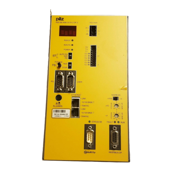
- Page 23 Overview PSS SB2 3006-3 ETH-2 DP-S PSS SB2 3006-3 ETH-2 DP-S PSS PWR 24 V RUN ST RUN FS POWER I 0.0 AUTO PG I 0.1 I 0.2 I 0.3 I 0.4 I 0.5 STOP USER ADDRESS +100 ETHERNET ONOFF R T (USER) FAULT PROFIBUS-DP...
- Page 24 6: Programming device interface RS 232 (minimum configuration: TxD, RxD, GND)/RS 485 7: User interface RS 232/RS 485 8: Pushbutton for switching on and off the RS 485 termination on the user interface 9: Supply voltage connection (24 VDC) 10: Inputs and test pulse outputs 11: Labelling strip for Ethernet address 12: ETH-2 interface with connection to ETHERNET via integrated switch (2 free ports);...
- Page 25 Overview Fig. 2-7: Front view of PSS SB2 3006-3 ETH-2 IBS-S 1: 4-digit display 2: LEDs for PSS operating mode and supply voltage 3: 3-position switch for selecting the standard section’s operating mode 4: Button for scrolling the error stack 5: 2-position switch for selecting the failsafe section’s operating mode 6: Programming device interface 2-14...
- Page 26 6: Programming device interface RS 232 (minimum configuration: TxD, RxD, GND)/RS 485 7: User interface RS 232/RS 485 8: Pushbutton for switching on and off the RS 485 termination on the user interface 9: Supply voltage connection (24 VDC) 10: Inputs and test pulse outputs 11: Labelling strip for Ethernet address 12: ETH-2 interface with connection to ETHERNET via integrated switch (2 free ports);...
- Page 27 Overview Notes 2-16 Operating Manual: PSS SB 3006-3 Series Artisan Technology Group - Quality Instrumentation ... Guaranteed | (888) 88-SOURCE | www.artisantg.com...
-
Page 28: Pss Sb2 3006-3 Eth-2 Dp-Spss Sb2 3006-3 Eth-2 Ibs-S
- PSS SB2 3006-3 ETH-2 - PSS SB2 3006-3 ETH-2 DP-S - PSS SB2 3006-3 ETH-2 IBS-S INFORMATION Drivers (standard function blocks) from the corresponding Pilz software package will be required in order to connect to the various standard bus systems: • ST-SB-DP-S: Driver for PROFIBUS-DP Slave •... -
Page 29: Product Modifications
(parts, devices, user program etc.) must be included in the assessment. For this reason, Pilz cannot accept liability for the correct classification into a category or requirement class. Operating Manual: PSS SB 3006-3 Series... -
Page 30: Safety Guidelines
Digital inputs (DI2) Depending on the application area and its respective regulations, the PSS may be used without test pulses for applications up to category 3 in accordance with EN 954-1 (03/97). The possibility of a short circuit occurring in the external wiring between different inputs or to L+ must be eliminated through appropriate wiring. -
Page 31: Emcd
Safety EMCD The safety system is designed for use in an industrial environment. Interference may occur if used within a domestic environment. Warranty and liability All claims to warranty and liability will be rendered invalid if: • The safety system was used contrary to the purpose for which it was intended •... -
Page 32: Function Description
Function Description The CPU controls the test pulse outputs, reads the inputs and processes / stores the user program and variable data. The failsafe section is designed to be multi-channel, i.e. different CPUs process the user program independently. A four-digit display and several LEDs provide information on the status of the safety system and indicate any errors. -
Page 33: Interfaces
Function Description Interfaces CPU interfaces The CPU of each programmable safety system in the PSS SB2 3006-3 series provides the following interfaces: • Programming device interface Combined RS 232 interface (minimum configuration: TxD, RxD, GND)/ RS 485 • User interface Combined RS 232/RS 485 interface For further information please refer to the “System Manual for the PSS-Range”. -
Page 34: Digital Inputs (Di2)
Digital inputs (DI2) All programmable safety systems in the PSS SB2 3006-3 series have six integral on-board inputs, which are suitable for connecting single and dual- channel input devices, with or without test pulses. Input signals must show a “High” (“1” signal) of 24 VDC (+15 ... +30 VDC) and a “Low” (“0” signal) of 0 VDC (-3 ... -
Page 35: Test Pulse Outputs
Function Description Test pulse outputs The two test pulse outputs T0 and T1 are suitable for testing the wiring of input devices. All safety-related inputs must operate in accordance with the failsafe principle (on switching off). Test pulses are allocated to inputs via the configurator in the system software (PG). -
Page 36: Installation
Installation General requirements Please note the following: • The safety system should be installed in an enclosure, e.g. control cabinet, that conforms to the protection class required for the environment. • When installing the system in an enclosure such as a control cabinet, the environmental data for the safety system must be taken into account. -
Page 37: Installing The Safety System
Installation Installing the safety system There are two options for installing the safety system. Both are illustrated in Fig. 5-1. Drill M5 or M6 holes in the control cabinet’s mounting plate, as shown in Fig. 5-1 (tolerance: +/-0.3 mm/0.012"). You will require 4 holes. Attach the safety system to the mounting plate in your control cabinet, using washers. -
Page 38: Installing The Safety System In A Control Cabinet
Installing the safety system in a control cabinet Distance from top min. 130 mm (5.12") 123 mm (4.84") PSS SB 3006-3 DP-S PSS PWR 24 V RUN ST RUN FS POWER I 0.0 AUTO PG I 0.1 I 0.2 I 0.3 I 0.4 220.4 mm I 0.5... - Page 39 Installation Notes Operating Manual: PSS SB 3006-3 Series Artisan Technology Group - Quality Instrumentation ... Guaranteed | (888) 88-SOURCE | www.artisantg.com...
-
Page 40: Supply Voltage
Supply Voltage General requirements Please note the following: • When selecting the power supply, please refer to the requirements stated under “Technical Details”. INFORMATION When test pulse outputs are used, the output circuits are designed to guarantee maximum safety. To achieve this, extensive tests are carried out internally. - Page 41 Supply Voltage • Connecting the external power supply on programmable safety systems without an INTERBUS interface - The external power supply should be connected to the PSS as shown in Fig. 6-1. PSS SB 3006-3 External power supply without INTERBUS interface +24 V (PSS PWR) 0 V X1...
- Page 42 • Connecting the external power supply on programmable safety systems with an INTERBUS interface and a common supply - If the PSS supply and the INTERBUS interface are fed from a common power supply, the external supply should be connected as shown in Fig.
- Page 43 Supply Voltage • Connecting external power supplys on programmable safety systems with an INTERBUS interface and a separate supply - If the PSS supply and the INTERBUS interface are fed from separate supplies, the two external supplies should be connected as shown in Fig.
- Page 44 • NOTICE There must be no direct connection between “N” and the 0 V output on the external power supply or external power supplies! • Connect together the 0V connections on all the 24 V power supplies and earth the 0 V mains at a single point. The connection of the 0 V supply to the central earth bar or earth fault monitor must be in accordance with relevant national regulations (e.g.
-
Page 45: Notes On Wiring
Supply Voltage Notes on wiring • Minimum range for cable cross sections on field connection terminals in , in accordance with EN 61131-2, 07/00: - Power supply: 1.5 (AWG16) ... 2.5 (AWG12) - Functional earth: 1.5 (AWG16) ... 2.5 (AWG12) •... -
Page 46: Wiring The Inputs And Test Pulse Outputs
Wiring the Inputs and Test Pulse Outputs Configuration of the screw terminals and connector description Supply voltage PSS SB2 3006-3 IBS-S X0 PSS PWR PSS PWR IBS PWR 24 V 24 V X2 IBS PWR (only on PSS with INTERBUS interface) DATA RUN ST LENGTH... -
Page 47: Notes On Wiring
Wiring the Inputs and Test Pulse Outputs Notes on wiring Where safety-related applications are concerned, it is essential that short circuits and open circuits are unable to cause a hazardous condition within a plant. The way in which this is done will depend on the degree of hazard within the plant itself, the switching frequency of the input devices and the level of safety of the input devices and actuators. - Page 48 • Connecting and laying the cables - Screened cables are not required for digital I/Os. However, if the connection cables have screening, it should be connected at one end. - Minimum range for cable cross sections on field connection terminals in , in accordance with EN 61131-2, 07/00: ¤...
-
Page 49: Digital Inputs (Di2)
Wiring the Inputs and Test Pulse Outputs Digital inputs (DI2) Features: • 6 digital inputs I0.0 ... I0.5 • Only input signals which operate in accordance with the failsafe principle (on switching off) are safety-related. • Signals may be connected using unscreened cables. •... -
Page 50: Example: Single-Channel, Failsafe Input Device, Without Test Pulse
Example: Single-channel, failsafe input device, without test pulse Features: • The input device must be approved for failsafe applications. • Please read the instructions provided with the input device. CAUTION! A short circuit in the cable between the input device and input with the 24 VDC line or between adjacent inputs will not be detected. -
Page 51: Example: Dual-Channel Input Devices, Without Test Pulses
Wiring the Inputs and Test Pulse Outputs Example: Dual-channel input devices, without test pulses Features: • This type of connection is mainly used for signal inputs with frequent operation. • The functionality of both input device channels should be monitored in the application program via feasibility checks (see example in the Programming Manual for the PSS-range). -
Page 52: Example: Single-Channel, Failsafe Input Device, With Test Pulse
Example: Single-channel, failsafe input device, with test pulse Features: • The input device must be approved for failsafe applications. • Please read the instructions provided with the input device. • The test pulse must be allocated to the input via the configurator on the programming device (see Programming Manual for the PSS-range). -
Page 53: Example: Dual-Channel, Failsafe Input Device, With Test Pulses
Wiring the Inputs and Test Pulse Outputs Example: Dual-channel, failsafe input device, with test pulses Features: • This type of connection is mainly used for signal inputs with infrequent operation. • The test pulse must be allocated to the input via the configurator on the programming device (see Programming Manual for the PSS-range). - Page 54 I 0.0 Input for other input I 0.1 devices I 0.2 I 0.3 Dual-channel input I 0.4 device with identical I 0.5 channels 24 V DC I 0.0 I 0.1 I 0.2 I 0.3 Dual-channel input I 0.4 device with identical I 0.5 channels 24 V DC...
-
Page 55: Dedicated Test Pulse Outputs
Wiring the Inputs and Test Pulse Outputs Dedicated test pulse outputs Features: • 2 test pulse outputs T0 and T1 • The test pulse must be allocated to the input via the configurator on the programming device (see Programming Manual for the PSS-range). •... -
Page 56: Interfaces
Interfaces General requirements We recommend you use screened cable for the RS 232/RS 485 interfaces. If unscreened cables are used, the interfaces may malfunction. • Earth the cable screening on both sides (e.g. on a bus bar). • If you are using longer cables and there is the possibility of transient currents, you can prevent these by using equipotential bonding cables. -
Page 57: Programming Device Interface ("Pg")
Interfaces Programming device interface (“PG”) The programming device interface is a combined RS 232/RS 485 interface. Both interfaces are available on a male 9-pin D-Sub connector. The interface enables communication between the programming device and the PSS. The termination can be activated via links within the connector (see Fig. 8-3 in the section entitled “RS 485 programming device interface”). -
Page 58: Programming Device Interface Rs 232
Programming device interface RS 232 The RS 232 interface for connecting the programming device is provided in a minimum configuration. The connections TxD, RxD and GND are available. INFORMATION To connect the PSS to the programming device via the RS 232 interface you will need a cable with a layout as shown in Fig. -
Page 59: Programming Device Interface Rs 485
Interfaces Programming device interface RS 485 If you need to cover longer distances between the programming device and PSS (from approx. 15 m), use the RS 485 interface on the PSS. If the programming device has no RS 485 interface, connect the RS 485 interface on the PSS to the RS 232 interface on the programming device via the C-PC-PAP-2 interface adapter (order no. -
Page 60: User Interface ("User")
User interface (“USER”) The user interface is a combined RS 232/RS 485 interface. Both interfaces are available on a male 9-pin D-Sub connector. NOTICE Never operate the combined RS 232 and RS 485 interface simultaneously or in parallel. The programmable safety system is not designed for this. Male D-Sub connector 9-pin RS 232... -
Page 61: User Interface Rs 232
INFORMATION To connect PX(T) display systems, PMI graphics systems and the Pilz MPI adapter to the RS 232 user interface on the PSS you will need a cable with a layout as shown in Fig. 8-5. This cable is available under order number 301 965. -
Page 62: User Interface Rs 485
User interface RS 485 A detailed description of the interface can be found in the “FS System Description” and “ST System Description” in the PSS-range manual package. The RS 485 interface has internal termination: 120 Ohm between A and B, 270 Ohm between A and 5 V and between B and GND. -
Page 63: Safetybus P Interface ("Safetybus P")
5: CAN_SHLD 6: n.c. 7: CAN_H (green) 8: Supply voltage for fibre-optic couplers from Pilz 9: n.c. n.c. = not connected Fig. 8-6: Configuration of the SafetyBUS p interface Interfaces for standard bus connections The standard bus interfaces are described in separate operating manuals. -
Page 64: Operation And Maintenance
Operation and Maintenance Commissioning • Install the programmable safety system as described in Chapter 5, “Installation”. • Connect the inputs and test pulse outputs as described in Chapter 7, “Wiring the Inputs and Test Pulse Outputs”. • Supply voltage for the PSS - as described in Chapter 6 “Supply Voltage” - connect and switch on. -
Page 65: Display Elements
Operation and Maintenance Display elements PSS functionality Signal RUN ST Standard section of PSS in “STOP” Lights green Standard section of PSS in “RUN” RUN FS Failsafe section of PSS in “STOP” Lights green Failsafe section of PSS in “RUN” Flashes green Major error Remedy: Read the error stack,... -
Page 66: Changing The Battery
If the battery voltage drops below 2.5 V, the CPU will issue the error message “S-04”. You should then change the battery, Only use a battery type that has been approved by Pilz (see chapter entitled “Technical Details”). Battery types that are approved by Pilz are “UL-Recognized”. - Page 67 Operation and Maintenance Switch off the supply voltage, remove connector and terminal PSS SB 3006-3 DP-S PSS PWR 24 V blocks. RUN ST RUN FS POWER Remove the cap from the I 0.0 AUTO PG I 0.1 I 0.2 I 0.3 “F-STACK”...
- Page 68 Remove the blanking plate and undo the screws. PSS SB 3006-3 DP-S PSS PWR 24 V RUN ST RUN FS POWER I 0.0 AUTO PG I 0.1 I 0.2 I 0.3 I 0.4 I 0.5 STOP USER ADDRESS +100 ONOFF R T (USER) FAULT PROFIBUS-DP...
- Page 69 Operation and Maintenance Notes Operating Manual: PSS SB 3006-3 Series Artisan Technology Group - Quality Instrumentation ... Guaranteed | (888) 88-SOURCE | www.artisantg.com...
-
Page 70: Technical Details
Technical Details Electrical data Supply voltage 24 VDC Tolerance 20 ... 30 VDC including residual ripple of max. ± 1.2 V Current consumption “PSS PWR” Max. 850 mA plus load currents taken from the test pulse outputs and load currents for SafetyBUS p fibre-optic couplers (25 mA per fibre-optic coupler) “IBS PWR”... - Page 71 Technical Details Battery Lithium, Type CR2477N (see accessories) Service life ca. 2 years SafetyBUS p Application range Failsafe applications conforming to EN 954-1, 03/97, DIN V 19250, 05/94 VDE 0116, 09/97 Status indicator Transmission rate Max. 500 kBit/s Cable runs Max.
- Page 72 Environmental data Protection type (EN 60529, 02/00) IP20 Mounting position Vertical Ambient temperature (EN 60068-2-14, 11/99) 0 ... 60 °C Storage temperature (EN 60068-2-1/-2, 07/94) -25 ... +70 °C Climatic suitability (EN 60068-2-78, 10/01) 93 % r.h. at 40 °C Condensation Not permitted Vibration (EN 60068-2-6, 04/95)
- Page 73 Technical Details Notes 10-4 Operating Manual: PSS SB 3006-3 Series Artisan Technology Group - Quality Instrumentation ... Guaranteed | (888) 88-SOURCE | www.artisantg.com...
-
Page 74: Appendix
Appendix Address of SafetyBUS p Club SafetyBUS p Club International e.V. Robert-Bosch-Straße 30 D-73760 Ostfildern Germany Tel. No.: +49 7 11 34 09-1 18 Fax No.: +49 7 11 34 09-4 49 E-Mail: info@safetybus.com Changes in the documentation Changes in Version 21 143-02 Change page page... - Page 75 Appendix Notes 11-2 Operating Manual: PSS SB 3006-3 Series Artisan Technology Group - Quality Instrumentation ... Guaranteed | (888) 88-SOURCE | www.artisantg.com...
- Page 76 Technical support Please refer to our Homepage +49 711 3409-444 for further details or contact our headquarters. Pilz GmbH & Co. KG Sichere Automation Felix-Wankel-Straße 2 73760 Ostfildern, Germany Telephone: +49 711 3409-0 Telefax: +49 711 3409-133 E-Mail: pilz.gmbh@pilz.de...
- Page 77 Artisan Technology Group is your source for quality new and certified-used/pre-owned equipment SERVICE CENTER REPAIRS WE BUY USED EQUIPMENT • FAST SHIPPING AND DELIVERY Experienced engineers and technicians on staff Sell your excess, underutilized, and idle used equipment at our full-service, in-house repair center We also offer credit for buy-backs and trade-ins •...
Need help?
Do you have a question about the PSS Series and is the answer not in the manual?
Questions and answers