Pilz PSS Series Operating Manual
Programmable safety systems
Hide thumbs
Also See for PSS Series:
- User manual ,
- Operating manual (77 pages) ,
- Installation manual (49 pages)

Related Manuals for Pilz PSS Series


Summary of Contents for Pilz PSS Series
- Page 1 (217) 352-9330 | Click HERE Find the Pilz PSS SB DI808 at our website:...
- Page 2 Programmable Safety Systems PSS-Range PSS SB DI8O8 Operating Manual Item No. 19 964-12 The spirit of safety. Artisan Technology Group - Quality Instrumentation ... Guaranteed | (888) 88-SOURCE | www.artisantg.com...
- Page 3 Artisan Technology Group - Quality Instrumentation ... Guaranteed | (888) 88-SOURCE | www.artisantg.com...
-
Page 4: Table Of Contents
PSS SB DI8O8 Contents Introduction Validity of the documentation Overview Intended use System requirements CPU versions System software versions Functions Inputs Detecting signals at the inputs Signal change behaviour Outputs Test pulse outputs Schematic internal wiring diagram Operation of the module on SafetyBUS p Supply voltage Display elements Installation... -
Page 5: Introduction
PSS SB DI8O8 Introduction This shortform explains the function and operation of the decentralised input/output module PSS SB DI8O8. The documentation is intended for instruction and should be retained for future reference. Validity of the documentation The PSS SB DI8O8 documentation is valid from Version 2.1 onwards. It is valid until new documentation is released. -
Page 6: Intended Use
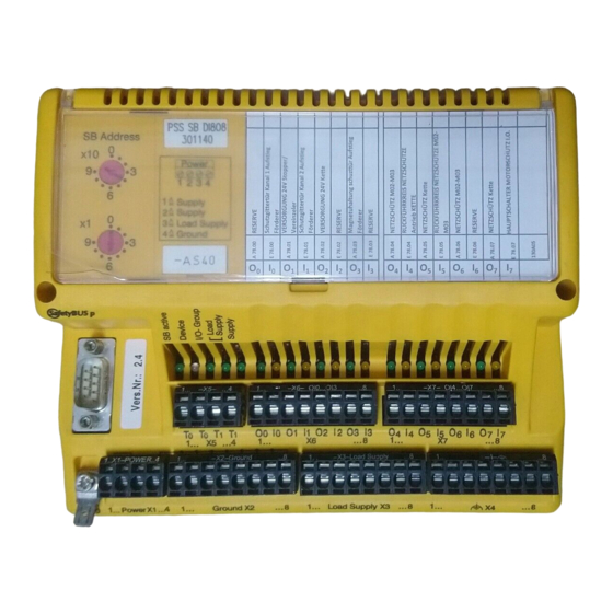
NOTICE Before installing the module you should read and consider the “PSS SB DI8O8 Installation Manual” and the “SafetyBUS p System Manual”. Intended use The PSS SB DI8O8 is a decentralised input/output module which has been designed for use as an input/output device on SafetyBUS p. System requirements CPU versions The PSS SB DI8O8 is supported by all SafetyBUS p-compatible safety... - Page 7 PSS SB DI8O8 1: Switch for setting the device address on SafetyBUS p 2: Labelling strip for the I/Os 3: SafetyBUS p interface 4: LEDs for operating status and supply voltage 5: Status LEDs for the I/Os 6: Terminal block for dedicated test pulses 7: Terminal blocks for I/Os 8: Connection terminal for the functional earth 9: Terminal block for the supply voltage...
-
Page 8: Functions
Functions Inputs The inputs are suitable for connecting single and dual-channel input devices, with or without test pulses. Input signals must show a “High” of 24 VDC (+15 ... +30 VDC) and a “Low” of 0 VDC (-3 ... +5 VDC). All inputs have input filters. Input status is transmitted to the CPU on the PSS master via SafetyBUS p. -
Page 9: Signal Change Behaviour
PSS SB DI8O8 : Pulse length for guaranteed signal detection for “1” or “0” signals (> Event Timeout) : Max. pulse length for pulse suppression on “1” or “0” signals (500 µs) Signal change behaviour If a signal change occurs at an input, the module will send an Event Telegram. -
Page 10: Outputs
Outputs 8 digital outputs are available on the module: • O ... O are positive-switching (“Load Supply”) 2 A outputs • O and O are negative-switching (“Ground”) 2 A outputs Positive-switching outputs are suitable for connecting resistive and inductive loads of 2 A maximum. They have an integral discharge circuit which means they are also suitable for connecting capacitive loads of up to 1 µF. - Page 11 PSS SB DI8O8 WARNING! When wiring an output with capacitance, you must be aware of the following: • An output that is switched off is tested by switching it on each cycle, approx. once every 2 minutes. • The pulse length of a switch-on or switch-off test is 200 µs •...
-
Page 12: Test Pulse Outputs
If the plant is sensitive to the fast on/off switching of the output test, individual outputs may be excluded from the test through the configuration. NOTICE In the case of outputs that are excluded from the output test, the PSS checks that their switch status is correct but does not check their actual ability to switch. -
Page 13: Schematic Internal Wiring Diagram
Operation of the module on SafetyBUS p The connection to SafetyBUS p is made via a male 9-pin D-Sub connector. Fibre-optic couplers from Pilz (like PSS SB SUB-D F0) can be connected to the SafetyBUS p interface. To enable the module to operate on SafetyBUS p, it must be given the device address set via the configurator in the system software. - Page 14 Test Test Load Supply Ground (2-channel) 6,6 nF Ground Load Supply 3,3 nF 2,4 M Supply Supply 24 V Schematic internal wiring diagram of the PSS SB DI8O8 Operating Manual Artisan Technology Group - Quality Instrumentation ... Guaranteed | (888) 88-SOURCE | www.artisantg.com...
-
Page 15: Supply Voltage
PSS SB DI8O8 Example: The device address is 36, inputs I to I belong to Section A, inputs I to I belong to Section B. So, taking I as an example: Address of I = 36 [5 + (Offset 16)] = 36.21 Output addresses: Input addresses: →... -
Page 16: Display Elements
Display elements LEDs for status display Each input and output is assigned an LED for status display. If the input or output is high, the corresponding LED will light. If it goes low, the LED will go out. LED “Supply” Indicates that the supply is present. -
Page 17: Installation
PSS SB DI8O8 Installation Free space for rail- mounting and for ventilation Recommended free space for wiring Installing the PSS SB DI8O8, dimensions stated in mm (") Dimensions in mm ("): H x W x D: 140 x 170 x 65 (5.51 x 6.69 x 2.56) The module can be attached to a 35 mm DIN-rail (top hat rail) or can be screwed on to mounting plate using fixing bolts (order no. -
Page 18: Commissioning
Commissioning General guidelines are given below, but you should always refer to the “PSS SB DI8O8 Installation Manual” (this is part of the “Safety BUS p” System Manual and is also enclosed with every Safety BUS p-compatible PSS): • Install the module INFORMATION If the module is attached to an earthed DIN rail, this will automatically cover the module's functional earth requirements. -
Page 19: Check List For Commissioning
PSS SB DI8O8 Check list for commissioning Confirm during Fill out when designing the plant and its configuration: commissioning: Information on the device address Address set Device address Output Designed Safety- Excluded Required reaktion in Error simulated as dual- related from case of error for safety-related... -
Page 20: Module Configuration
Module configuration The procedure for configuring SafetyBUS p and the PSS SB DI8O8 module is described in the online help of the PSS WIN-PRO system software. Operating Manual Artisan Technology Group - Quality Instrumentation ... Guaranteed | (888) 88-SOURCE | www.artisantg.com... -
Page 21: Technical Details
ENGLISH PSS SB DI8O8 Technical details Electrical data Supply voltage "Supply": 24 V DC "Load Supply" 24 VDC Tolerance 20 ... 30 VDC including residual ripple of max. ± 1.2 V Input capacitance 570 µF Power consumtion "Supply": 150 mA plus load currents from the test pulse outputs and load currents for fibre-optic couplers (25 mA per fibre- optic coupler);... - Page 22 ENGLISH Limitation of inductive switch-off Approx. U B - 60 VDC Simultaneity 100 % at max. 10 A, all outputs Residual current at “0” signal 0 mA Signal level at the outputs “0” signal 0 VDC “1” signal and 2.5 A load - 1 VDC Minimum output switch delay <...
- Page 23 PSS SB DI8O8 Environmental data Protection type (EN 60529) IP20 Mounting position Ambient temperature (EN 60068-2-14) 0 ... 60 °C Storage temp. (EN 60068-2-1/-2) -25 ... +70 °C Climatic suitability (EN 60068-2-78) Max. 95 % r.h. Condensation Not permitted Vibration (EN 60068-2-6) Frequency range: 10 ...
-
Page 24: Changes In The Documentation
Changes in the documentation Changes from version I to version II Change p. no. p. no. Description of the positive-switching outputs Description of the tests to be carried out by the user on outputs that are excluded from the output test Function of the LED “SB active”... - Page 25 PSS SB DI8O8 Changes from version IV to version V Change p. no. p. no. 14 ff. 14 ff. Procedure when configuring test pulses and outputs using system software PSS SW PG, from version 4.1. Condensation is not permitted. Changes from version V to version VI Change p.
- Page 26 Changes from version VIII to version IX Change p. no. p. no. fibre-optic couplers can now be connected to the SafetyBUS p interface cable length between test pulse output and input max. 200 m Changes from version IX to version X Change p.
- Page 27 PSS SB DI8O8 Changes in version 19 964-12 Change p. no. p. no. Norms updated New: section „System requirements“ INFO deleted 17-21 Module configuration Technical details was amended New: "The version of the standards current at 2004-04 shall apply." Operating Manual Artisan Technology Group - Quality Instrumentation ...
- Page 28 In many countries we are www.pilz.com represented by sales partners. Please refer to our Homepage for further details or contact our headquarters. Pilz GmbH & Co. KG Sichere Automation Felix-Wankel-Straße 2 73760 Ostfildern, Germany Telephone: +49 711 3409-0 Telefax: +49 711 3409-133 E-Mail: pilz.gmbh@pilz.de...
Need help?
Do you have a question about the PSS Series and is the answer not in the manual?
Questions and answers