
Related Manuals for Pilz PNOZ m EF Multi Link


Summary of Contents for Pilz PNOZ m EF Multi Link
- Page 1 PNOZ m EF Multi Link Configurable, safe small controllers PNOZmulti 2 Operating Manual-1003018-EN-06...
- Page 2 Preface This document is the original document. All rights to this documentation are reserved by Pilz GmbH & Co. KG. Copies may be made for the user's internal purposes. Suggestions and comments for improving this documenta- tion will be gratefully received.
-
Page 3: Table Of Contents
Wiring............................Connection..........................Download modified project to the PNOZmulti system .............. Operation ..........................LED indicators .......................... Fault detection .......................... Technical details ........................Safety characteristic data ......................Order reference ........................Product ............................. Accessories ..........................Operating Manual PNOZ m EF Multi Link 1003018-EN-06... -
Page 4: Introduction
Introduction Introduction Validity of documentation This documentation is valid for the product PNOZ m EF Multi Link. It is valid until new docu- mentation is published. This operating manual explains the function and operation, describes the installation and provides guidelines on how to connect the product. - Page 5 Introduction INFORMATION This gives advice on applications and provides information on special fea- tures. Operating Manual PNOZ m EF Multi Link 1003018-EN-06...
-
Page 6: Overview
Can be configured in the PNOZmulti Configurator Point-to-point connection via 4-core shielded, twisted-pair cable 32 virtual inputs and 32 virtual outputs Status indicators Max. 4 PNOZ m EF Multi Link can be connected to the base unit LED indicators for – Operating status – Error –... -
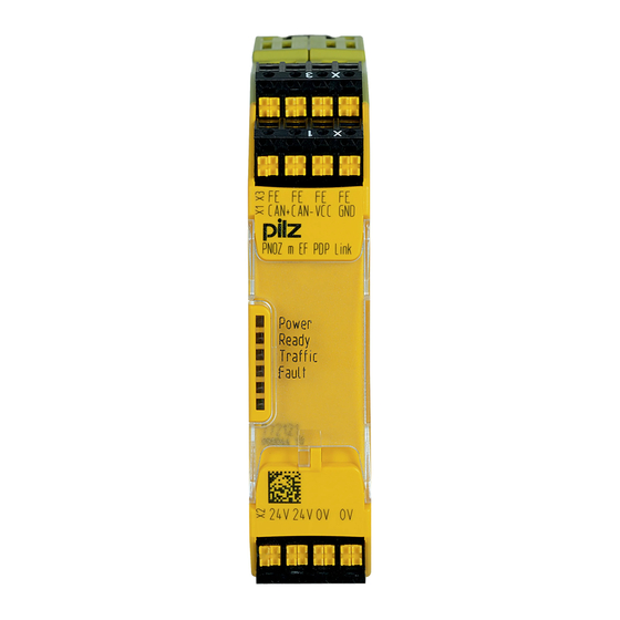
Page 7: Front View
Overview Front view Power Ready Link Fault Legend: – 0 V, 24 V:Supply connections – FE: Functional earth Link: Connection LEDs: – Power – Ready – Link – Fault Operating Manual PNOZ m EF Multi Link 1003018-EN-06... -
Page 8: Safety
Example: Protected inside space or control cabinet with protection type IP54 and corres- ponding air conditioning. The product PNOZ m EF Multi Link can be used in furnaces in accordance with EN 298. The following is deemed improper use in particular... -
Page 9: Safety Regulations
(e.g. Electrical and Electronic Equipment Act). 3.3.5 For your safety The unit meets all the necessary conditions for safe operation. However, you should always ensure that the following safety requirements are met: Operating Manual PNOZ m EF Multi Link 1003018-EN-06... - Page 10 Do not open the housing or make any unauthorised modifications. Please make sure you shut down the supply voltage when performing maintenance work (e.g. exchanging contactors). Operating Manual PNOZ m EF Multi Link | 10 1003018-EN-06...
-
Page 11: Function Description
The safety device remains effective in the case of a component failure. Functions The link module PNOZ m EF Multi Link is used to safely transfer the input information from 32 virtual inputs and 32 virtual outputs between two PNOZmulti systems. One link module is assigned to each base unit. -
Page 12: System Reaction Time
Calculation of the maximum reaction time between an input switching off and a linked out- put in the system switching off is described in the document "System Expansion". Block diagram 24V 0V n.c.FE CA- CB+ CB- CGround Power Operating Manual PNOZ m EF Multi Link | 12 1003018-EN-06... -
Page 13: Installation
Electrostatic discharge can damage components. Ensure against discharge before touching the product, e.g. by touching an earthed, conductive sur- face or by wearing an earthed armband. Dimensions in mm 22,5 (0.88") Operating Manual PNOZ m EF Multi Link | 13 1003018-EN-06... -
Page 14: Connect The Base Unit And Expansion Modules
Please refer to the document "PNOZmulti System Expansion" for details of the number of modules that can be connected to the base unit and the module types. Operating Manual PNOZ m EF Multi Link | 14 1003018-EN-06... -
Page 15: Commissioning
The max. cable length between two link modules on a connection with one link module – PNOZ ml1p <V2.0: 100 m – PNOZ ml1p from V2.0, PNOZ mml1p, PNOZ m EF Multi Link: 1000 m Connect the inputs and outputs from two link modules with a 4-core shielded cable. The cables must be twisted in pairs. -
Page 16: Connection
Shield CGround Supply voltage n.c. Connecting 2 base units PNOZmulti 2 via PNOZ m EF Multi Link PNOZ m EF Multi Link PNOZ m EF Multi Link Download modified project to the PNOZmulti system As soon as an additional expansion module has been connected to the system, the project must be amended in the PNOZmulti Configurator and downloaded back into the base unit. -
Page 17: Operation
Operation Operation The PNOZmulti safety system is ready for operation when the "POWER" and "RUN" LEDs on the base unit and the "READY" LED on the PNOZ m EF Multi Link are lit continuously. LED indicators Legend LED on LED flashes... -
Page 18: Fault Detection
Defective link module: The corresponding base unit switches to a STOP condition. The virtual outputs on the link module are set to zero. The connected base unit remains in a RUN condition. Operating Manual PNOZ m EF Multi Link | 18 1003018-EN-06... -
Page 19: Technical Details
EN 60068-2-30, EN 60068-2-78 Condensation during operation Not permitted Max. operating height above sea level 2000 m EN 61131-2 Vibration In accordance with the standard EN 60068-2-6 Frequency 5 - 55 Hz Acceleration Operating Manual PNOZ m EF Multi Link | 19 1003018-EN-06... - Page 20 Conductor cross section with spring-loaded terminals: Flexible with/without crimp connector 0,2 - 2,5 mm², 24 - 12 AWG Spring-loaded terminals: Terminal points per connec- tion Stripping length with spring-loaded terminals 9 mm Operating Manual PNOZ m EF Multi Link | 20 1003018-EN-06...
-
Page 21: Safety Characteristic Data
A safety function's SIL/PL values are not identical to the SIL/PL values of the units that are used and may be different. We recommend that you use the PAScal software tool to calculate the safety function's SIL/PL values. Operating Manual PNOZ m EF Multi Link | 21 1003018-EN-06... -
Page 22: Order Reference
Screw terminals PNOZ Screw terminals, 10 piece 793 539 mmc2p,mml1p 10 pcs. Terminator, jumper Product type Features Order no. PNOZ mm0.xp connector Jumper yellow/black to connect the modules, 10 pieces 779 260 left Operating Manual PNOZ m EF Multi Link | 22 1003018-EN-06... - Page 23 We are represented internationally. Please refer to our homepage www.pilz.com for further details or contact our headquarters. Headquarters: Pilz GmbH & Co. KG, Felix-Wankel-Straße 2, 73760 Ostfildern, Germany Telephone: +49 711 3409-0, Telefax: +49 711 3409-133, E-Mail: info@pilz.com, Internet: www.pilz.com...
Need help?
Do you have a question about the PNOZ m EF Multi Link and is the answer not in the manual?
Questions and answers