Pilz PSS Series Operating Manual
Programmable safety systems
Hide thumbs
Also See for PSS Series:
- User manual ,
- Operating manual (77 pages) ,
- Installation manual (49 pages)

Related Manuals for Pilz PSS Series


Summary of Contents for Pilz PSS Series
- Page 1 (217) 352-9330 | Click HERE Find the Pilz PSS1 DI2O Z at our website:...
- Page 2 Programmable Safety Systems PSS-Range PSS DI2O Z, PSS1 DI2O Z Operating Manual Item No. 20 335-03 The spirit of safety.
- Page 3 All rights to this manual are reserved by Pilz GmbH & Co. KG. Copies may be made for internal purposes. While every effort has been made to ensure that the information in this manual is accurate, no responsibility can be accepted for errors or omissions contained within it.
-
Page 4: Table Of Contents
Contents Introduction Validity of documentation Overview of documentation Definition of symbols Overview Front view Safety Intended use System requirements CPU versions System software versions Categories in accordance with EN 954-1 Digital inputs (DI2) Dual-pole outputs (DOZ) Function Description Digital inputs DI2 Digital outputs DOZ Operating Manual: PSS(1) DI2O Z... - Page 5 Contents Wiring Configuration Notes on wiring Example: Single-channel, failsafe input device, without test pulse Example: Dual-channel input devices, without test pulses 5-6 Example: Single-channel, failsafe input device, with test pulse Example: Dual-channel, failsafe input device, with test pulse 5-10 Example: Dual-pole outputs 5-12 Operation and Maintenance Commissioning...
-
Page 6: Introduction
Introduction This operating manual explains the function and operation of the centralised input/output module PSS(1) DI2O Z. Please also refer to the following documentation: During installation: • Installation Manual: PSS 3000/PSS 3100 Series During configuration: • PSS-Range Safety Manual • Installation Manual: PSS 3000/PSS 3100 Series •... -
Page 7: Overview Of Documentation
Introduction Overview of documentation Introduction The introduction is designed to familiarise you with the contents, structure and specific order of this manual. Overview This chapter provides information on the module’s most important features. Safety This chapter must be read as it contains important information on safety regulations and intended use. -
Page 8: Definition Of Symbols
Definition of symbols Information in this manual that is of particular importance can be identified as follows: DANGER! This warning must be heeded! It warns of a hazardous situation that poses an immediate threat of serious injury and death and indicates preventive measures that can be taken. - Page 9 Introduction Notes Operating Manual: PSS(1) DI2O Z...
-
Page 10: Overview
Overview The module PSS(1) DI2O Z has 16 digital inputs and 8 dual-pole 2 A outputs. The inputs can be used to monitor emergency stop circuits, for example. They are generally suitable for connecting: • Single-channel safety-related input devices - with test pulses - without test pulses •... -
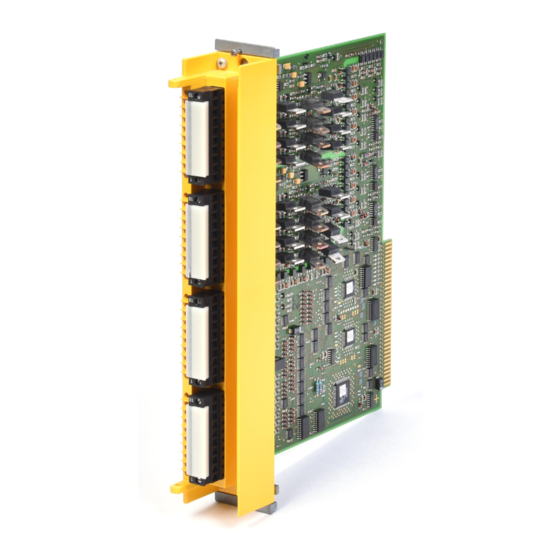
Page 11: Front View
Overview Front view Fig. 2-1: Front view of the PSS(1) DI2O Z Operating Manual: PSS(1) DI2O Z... -
Page 12: Safety
Safety Intended use The input/output module PSS(1) DI2O Z is designed for use in safety- related applications. It is used in the failsafe section of the PSS. The PSS DI2O Z module is designed for use on a module rack from the PSS 3000 series. -
Page 13: System Software Versions
The following system software is required in order to configure the module: • PSS SW PG from Version 4.0 • PSS WIN-PRO from Version 1.0 Please contact Pilz if you have an older version of the system software. Categories in accordance with EN 954-1 WARNING! -
Page 14: Dual-Pole Outputs (Doz)
Dual-pole outputs (DOZ) The dual-pole outputs can be used for applications up to Category 4 in accordance with EN 954-1 (11/94). Operating Manual: PSS(1) DI2O Z... - Page 15 Safety Notes Operating Manual: PSS(1) DI2O Z...
-
Page 16: Function Description
Function Description Digital inputs DI2 The module PSS(1) DI2O Z has 16 DI2 type inputs (I0 ... I15). Input signals must show a “High” of 24 VDC (+15 ... +30 VDC) or a “Low” of 0 VDC (-3 ... +5 VDC). The inputs have a filter and are galvanically isolated from the control electronics through optocouplers and converters. - Page 17 Function Description Diagnostic circuitry checks the function of the outputs. On outputs that are switched on, the CPU will alternately switch off the “+” and “-” terminals as part of each cycle. This is to check that the corresponding output transistors can be switched off and that there is no interruption to the load.
-
Page 18: Wiring
Wiring Configuration Connector description: Digital inputs I0 ... I7 Digital inputs I8 ... I15 Dual-pole outputs O16 ... O19 Dual-pole outputs O20 ... O23 Fig. 5-1: Configuration of the PSS(1) DI2O Z Operating Manual: PSS(1) DI2O Z... -
Page 19: Notes On Wiring
Wiring Notes on wiring In addition to the “Notes on wiring” in the “PSS 3000/PSS 3100 Series Installation Manual”, please note the following: • Safety-related input signals must operate in accordance with the failsafe principle (on switching off). • In the user program, make sure that a “0” signal from the module always causes the relevant outputs to shut down. - Page 20 Notes Operating Manual: PSS(1) DI2O Z...
-
Page 21: Example: Single-Channel, Failsafe Input Device, Without Test Pulse
Wiring Example: Single-channel, failsafe input device, without test pulse Features: • Depending on the application area and its respective regulations, this connection diagram is suitable for input devices with frequent and infrequent operation in accordance with EN 954-1, up to Category 2. The possibility of a short circuit occurring in the external wiring between different inputs or against L+ must be eliminated through appropriate wiring. - Page 22 Single-channel, failsafe input device Fig. 5-2: Example: Single-channel, failsafe input device, without test pulse Please ensure safety regulations and EMC guidelines are met! Operating Manual: PSS(1) DI2O Z...
- Page 23 Wiring Example: Dual-channel, failsafe input devices, without test pulses Features: • Depending on the application area and its respective regulations, this connection diagram is suitable for input devices with frequent operation and diverse channels, up to Category 4 in accordance with EN 954-1, provided the functionality of both input device channels is monitored in the user program via a feasibility check (see example in the Programming Manual).
- Page 24 Dual-channel input device with pulsed semiconductor outputs Input for other input devices Dual-channel input device with identical (homogenous) channels (max. Category 3) Dual-channel input device with different (diverse) channels Fig. 5-3: Example: Dual-channel input devices, without test pulses Please ensure safety regulations and EMC guidelines are met! Operating Manual: PSS(1) DI2O Z...
-
Page 25: Example: Single-Channel, Failsafe Input Device, With Test Pulse
Wiring Example: Single-channel, failsafe input device, with test pulse Features: • Depending on the application area and its respective regulations, this connection diagram is suitable for applications up to Category 2 in accordance with EN 954-1. • The input device must be approved for failsafe applications. •... - Page 26 *With cable runs > 200 m 1 kΩ* Single- channel, failsafe input device Test pulse Additional input devices Fig. 5-4: Example: Single-channel, failsafe input device, with test pulse Please ensure safety regulations and EMC guidelines are met! Operating Manual: PSS(1) DI2O Z...
-
Page 27: Example: Dual-Channel, Failsafe Input Device, With Test Pulse
Wiring Example: Dual-channel, failsafe input device, with test pulse Features: • Depending on the application area and its respective regulations, this connection diagram is suitable for applications up to Category 4 in accordance with EN 954-1. • This type of connection is mainly used for signal inputs with infrequent operation. - Page 28 Dual-channel input device with identical channels Dual-channel input device with diverse channels Test pulse Test pulse Additional input devices Fig. 5-5: Example: Dual-channel, failsafe input device, with test pulse Please ensure safety regulations and EMC guidelines are met! Operating Manual: PSS(1) DI2O Z 5-11...
-
Page 29: Example: Dual-Pole Outputs
Wiring Example: Dual-pole outputs Features: • With dual-channel operation, the outputs may be used for applications up to Category 4 in accordance with EN 954-1 (11/94) (depending on the application area and its respective regulations). • Output current: 2 A •... - Page 30 Fig. 5-6: Example: Dual-pole outputs Operating Manual: PSS(1) DI2O Z 5-13...
- Page 31 Wiring Notes 5-14 Operating Manual: PSS(1) DI2O Z...
-
Page 32: Operation And Maintenance
Operation and Maintenance Commissioning • Install the module on the module rack as described in the “PSS 3000/ PSS 3100 Series Installation Manual”. • Connect the module as described in the chapter entitled “Wiring”. CAUTION! Electrostatic discharge can damage components on the module. Ensure against discharge before touching the module, e.g. - Page 33 Operation and Maintenance Notes Operating Manual: PSS(1) DI2O Z...
-
Page 34: Technical Details
Technical Details Electrical data Supply voltage 24 VDC Tolerance range 20 ... 30 VDC including residual ripple Current consumption 480 mA via backboard bus Galvanic isolation Yes (optocoupler, converter) Polarity protection Connection type Screw terminals, max. 2.5 mm (AWG 12) Outputs Number of outputs Potential isolation... - Page 35 Technical Details Input delay 1 ms ≤ 300 µs (requirement: in the PSS Configurator, Pulse suppression ≥ 3 ms must be configured under “Max. delay of digital inputs” and “DI test time”) Status display One LED per input Environmental data Protection type (EN 60 529, 10/91) IP20 (installed in module rack) Mounting position...
-
Page 36: Power Dissipation
Power dissipation P = P • P : Basic power dissipation • P :Power dissipation on one output at a “1” signal, without load • P :Power dissipation on one output at a “1” signal, under load • P : Power dissipation on one input at a “1” signal •... - Page 37 Technical Details Notes Operating Manual: PSS(1) DI2O Z...
-
Page 38: Appendix
Appendix Changes in the documentation Changes in Version 20 335-03 The operating manual was completely revised. Operating Manual: PSS(1) DI2O Z... - Page 39 Appendix Notes Operating Manual: PSS(1) DI2O Z...
- Page 40 In many countries we are represented by sales partners. Please refer to our Homepage for further details or contact our headquarters. Pilz GmbH & Co. KG Sichere Automation Felix-Wankel-Straße 2 73760 Ostfildern, Germany Telephone: +49 711 3409-0 Telefax: +49 711 3409-133 E-Mail: pilz.gmbh@pilz.de...
Need help?
Do you have a question about the PSS Series and is the answer not in the manual?
Questions and answers