
Related Manuals for Pilz PSS 3075-3 Series


Summary of Contents for Pilz PSS 3075-3 Series
- Page 1 PSS 3075-3 Series ® Programmable control systems PSS Operating Manual – Item No. 21 071-10...
-
Page 3: Table Of Contents
PSS SB 3075-3 ETH-2 CANopen 2-16 Safety Intended use Product modifications Categories in accordance with EN 954-1 Digital inputs (DI2) Single-pole outputs (DOS) Dual-pole outputs (DOZ) Safety guidelines Use of qualified personnel EMCD Warranty and liability Disposal Operating Manual: PSS 3075-3 Series... - Page 4 PSS SB 3075-3 ETH-2 SE Installing the safety system PSS SB 3075-3 DP-S, PSS SB 3075-3 CANopen and PSS SB 3075-3 ETH-2 CANopen Installing the safety system in a control cabinet Supply Voltage General requirements Notes on wiring Operating Manual: PSS 3075-3 Series...
- Page 5 Programming device interface RS 485 User interface (“USER”) User interface RS 232 User interface RS 485 SafetyBUS p interface (“SafetyBUS p”) Interfaces for standard bus connections Operation and Maintenance Commissioning Faults PSS and SafetyBUS p functionality Standard bus functionality Operating Manual: PSS 3075-3 Series...
- Page 6 Display elements PSS functionality SafetyBUS p functionality Standard bus functionality Changing the battery Technical Details 10-1 Derating diagrams 10-6 Accessories 10-7 Appendix 11-1 Address of Safety Network International e.V. 11-1 Changes in the documentation 11-1 Operating Manual: PSS 3075-3 Series...
-
Page 7: Introduction
Manual” from the Safety BUS p manual package. You will need to be conversant with the information in these manuals in order to fully understand this manual. This documentation is intended for instruction and should be retained for future reference. Operating Manual: PSS 3075-3 Series... -
Page 8: Validity Of Documentation
Introduction Validity of documentation This documentation is valid for the following programmable safety systems from the PSS 3075-3 series: • PSS 3075-3 from Version 1.0 • PSS 3075-3 DP-S from Version 1.0 • PSS 3075-3 NR from Version 1.0 • PSS SB 3075-3 from Version 1.0 •... -
Page 9: Overview Of Documentation
This chapter describes the configuration of the available interfaces. Operation and Maintenance This chapter explains how to commission the safety systems and advises on what to do if a fault occurs. 10 Technical Details 11 Appendix Operating Manual: PSS 3075-3 Series... -
Page 10: Definition Of Symbols
This describes a situation in which the unit(s) could be damaged and also provides information on preventive measures that can be taken. INFORMATION This gives advice on applications and provides information on special features, as well as highlighting areas within the text that are of particular importance. Operating Manual: PSS 3075-3 Series... -
Page 11: Overview
Overview A PSS from the PSS 3075-3 series is a complete programmable safety system in a single unit. The device descriptions provide information on their function. The description are made up of combinations of letters and numbers. • The PSS 3075-3 contains:... - Page 12 • The standard bus interfaces are described in separate operating manuals. The necessary operating manuals are supplied with the rele- vant unit types. • Drivers (standard function blocks) from the corresponding Pilz software package will be required in order to connect to the various standard bus systems.
- Page 13 Notes Operating Manual: PSS 3075-3 Series...
-
Page 14: Front Views
Overview Front views PSS 3075-3, PSS 3075-3 NR Fig. 2-1: Front view of PSS 3075-3 Operating Manual: PSS 3075-3 Series... - Page 15 9: Supply voltage connection (24 VDC) for internal supply of the safety system and the outputs at X1, X2 10: Digital outputs and test pulse outputs 11: Digital inputs 12: Functional earth connection 13: Supply voltage connection (24 VDC) for outputs at X8, X9 Operating Manual: PSS 3075-3 Series...
-
Page 16: Pss 3075-3 Dp-S
Overview PSS 3075-3 DP-S Fig. 2-2: Front view of PSS 3075-3 DP-S Operating Manual: PSS 3075-3 Series... - Page 17 14: 2-position switch for selecting the station address (PROFIBUS-DP) 15: Rotary switch for setting the station address (PROFIBUS-DP) 16: LED for status of PROFIBUS-DP 17: PROFIBUS-DP interface INFORMATION Please refer also to the manual: “PROFIBUS-DP for Compact 3 Generati- on PSS”. Operating Manual: PSS 3075-3 Series...
-
Page 18: Pss Sb 3075-3
Overview PSS SB 3075-3 Fig. 2-3: Front view of PSS SB 3075-3 Operating Manual: PSS 3075-3 Series... - Page 19 10: Digital outputs and test pulse outputs 11: Digital inputs 12: Functional earth connection 13: Supply voltage connection (24 VDC) for outputs at X8, X9 14: LED for status of SafetyBUS p 15: SafetyBUS p interface Operating Manual: PSS 3075-3 Series...
-
Page 20: Pss Sb 3075-3 Dp-S
Overview PSS SB 3075-3 DP-S Fig. 2-4: Front view of PSS SB 3075-3 DP-S 2-10 Operating Manual: PSS 3075-3 Series... - Page 21 16: LED for status of PROFIBUS-DP 17: PROFIBUS-DP interface 18: LED for status of SafetyBUS p 19: SafetyBUS p interface INFORMATION Please refer also to the manual: “PROFIBUS-DP for Compact 3 Generati- on PSS” Operating Manual: PSS 3075-3 Series 2-11...
-
Page 22: Pss Sb 3075-3 Eth-2, Pss Sb 3075-3 Eth-2 Se
Overview PSS SB 3075-3 ETH-2, PSS SB 3075-3 ETH-2 SE Fig. 2-5: Front view of PSS SB 3075-3 ETH-2 2-12 Operating Manual: PSS 3075-3 Series... - Page 23 - Status of network connection (LINK) - Status of data traffic (TRAFFIC) 16: LED for status of SafetyBUS p 17: SafetyBUS p interface INFORMATION Please refer also to the manual: “ETH-2 for Compact 3rd Generation PSS”. Operating Manual: PSS 3075-3 Series 2-13...
-
Page 24: Pss Sb 3075-3 Canopen
Overview PSS SB 3075-3 CANopen Fig. 2-6: Front view of PSS SB 3075-3 CANopen 2-14 Operating Manual: PSS 3075-3 Series... - Page 25 17: LED for the CANopen data cable status 18: CANopen interface 19: LED for status of SafetyBUS p 20: SafetyBUS p interface INFORMATION Please refer also to the manual: “CANopen for Compact 3 Generation PSS”. Operating Manual: PSS 3075-3 Series 2-15...
-
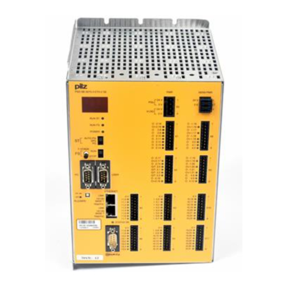
Page 26: Pss Sb 3075-3 Eth-2 Canopen
Overview PSS SB 3075-3 ETH-2 CANopen Fig. 2-7: Front view of PSS SB 3075-3 ETH-2 CANopen 2-16 Operating Manual: PSS 3075-3 Series... - Page 27 (2 free ports); LEDs on each port for - Status of network connection (LINK) - Status of data traffic (TRAFFIC) INFORMATION Please refer also to the manual: “CANopen for Compact 3 Generation PSS” and “ETH-2 for Compact 3 Generation PSS”. Operating Manual: PSS 3075-3 Series 2-17...
- Page 28 Overview Notes 2-18 Operating Manual: PSS 3075-3 Series...
-
Page 29: Safety
Safety Intended use Programmable safety systems from the PSS 3075-3 series are intended for use as follows: • Safety-related applications in the PSS failsafe section • Non-safety-related applications in the PSS standard section INFORMATION The following system software is required in order to program the safety systems: •... -
Page 30: Product Modifications
Please note: To achieve the corresponding category or requirement class, the whole system including all safety-related components (parts, devices, user program etc.) must be included in the assessment. For this reason, Pilz cannot accept liability for the correct classification into a category or requirement class. Digital inputs (DI2) -
Page 31: Single-Pole Outputs (Dos)
• All health and safety / accident prevention regulations for the particular area of application must be observed. • Before using the unit it is necessary to perform a safety assessment in accordance with the Machinery Directive 98/37/EC. Operating Manual: PSS 3075-3 Series... -
Page 32: Use Of Qualified Personnel
• Any type of modification has been made (e.g. exchanging components on the PCB boards, soldering work etc.). Disposal The programmable safety system must be disposed of properly when it reaches the end of its service life. Operating Manual: PSS 3075-3 Series... -
Page 33: Function Description
A four-digit display and several LEDs provide information on the status of the safety system and indicate any errors. Interfaces CPU interfaces The CPU of each programmable safety system in the PSS 3075-3 series provides the following interfaces: • Programming device interface Combined RS 232 interface (minimum configuration: TxD, RxD, GND)/ RS 485 •... -
Page 34: Inputs
Function Description Inputs Programmable safety systems from the PSS 3075-3 series have 48 digital inputs (DI2), 6 of which can be configured as alarm inputs (DIF). The digital input signals must show a “High” (“1” signal) of 24 VDC (+15 ... -
Page 35: Outputs
Description” from the “PSS System Manual for the compact/modular PSS” Outputs Programmable safety systems from the PSS 3075-3 series have 18 single- pole outputs (DOS) and 9 dual-pole outputs (DOZ). 4 of the single-pole outputs can be configured as test pulse outputs (DOT). - Page 36 (output’s diode not lit up). If you then generate a short circuit between the output and 0 V, the desired error reaction should occur. In the worst case, the error reaction should occur within 30 minutes. Operating Manual: PSS 3075-3 Series...
- Page 37 Each time SB255, function 2 is called, data words DW200, DW201 and DW202 must be written in full to ensure that outputs are not excluded from the power-up test unintentionally, due to data words being unwittingly overwritten during the program cycle. Operating Manual: PSS 3075-3 Series...
- Page 38 DB003 DW200 Slot number on the PSS 3075-3 series: 2 / 4 DW201 Masks for outputs 2.00 ... 2.15 / 4.00 ... 4.15 If this is set on a bit belonging to an output, the power-up test for this output will be deactivated.
-
Page 39: Dual-Pole Outputs (Doz)
PSS will switch to a STOP condition, switch off the outputs and send a message to the CPU-display. All outputs are protected against short-circuit, overload and excess temperature. They can switch both resistive and inductive loads. Operating Manual: PSS 3075-3 Series... -
Page 40: Configuration Coding
C003 I0.16 - I0.31 C003 I1.00 - I1.09 C003 O1.16 - O1.21 C011 O2.00 - O2.03 C017 O2.08 - O2.15 O2.16 - O2.18 C011 I3.00 - I3.05 D002 O4.00 - O4.02 C015 O4.08 - O4.10 Operating Manual: PSS 3075-3 Series... -
Page 41: Installation
Drill M4 holes in the control cabinet’s mounting plate, as shown in the illustrations (tolerance: +/-0.3 mm/0.012"). Attach the safety system to the mounting plate in your control cabinet, using washers. Operating Manual: PSS 3075-3 Series... -
Page 42: Installing The Safety System Pss 3075-3, Pss 3075-3 Nr
Fig. 5-1: Installation options for the programmable safety system PSS 3075-3 and PSS 3075-3 NR Dimensions stated in mm (") Dimensions in mm (") excluding interfaces and operating controls : H x W x D: 246.4 x 123.6 x 162 (9.70" x 4.87" x 6.38") Operating Manual: PSS 3075-3 Series... -
Page 43: Installing The Safety System Pss 3075-3 Dp-S, Pss Sb 3075-3, Pss Sb 3075-3 Eth-2 And Pss Sb 3075-3 Eth-2 Se
PSS SB 3075-3, PSS SB 3075-3 ETH-2 and PSS SB 3075-3 ETH-2 SE Dimensions stated in mm (") Dimensions in mm (") excluding interfaces and operating controls : H x W x D: 246.4 x 160.2 x 162 (9.70" x 6.31" x 6.38") Operating Manual: PSS 3075-3 Series... -
Page 44: Installing The Safety System Pss Sb 3075-3 Dp-S, Pss Sb 3075-3 Canopen And Pss Sb 3075-3 Eth-2 Canopen
PSS SB 3075-3 CANopen and PSS SB 3075-3 ETH-2 CANopen Dimensions stated in mm (") Dimensions in mm (") excluding interfaces and operating controls : H x W x D: 246.4 x 196.8 x 162 (9.70" x 7.58" x 6.38") Operating Manual: PSS 3075-3 Series... -
Page 45: Installing The Safety System In A Control Cabinet
Installing the safety system in a control cabinet Fig. 5-4: Installing safety systems from the PSS 3075-3 series in a control cabinet (example: PSS 3075-3), dimensions stated in mm (") Operating Manual: PSS 3075-3 Series... - Page 46 Installation Notes Operating Manual: PSS 3075-3 Series...
-
Page 47: Supply Voltage
Safe electrical isolation must be ensured for the external 24 V supply. Failure to do so could result in electric shock. Power supplies must conform to EN 60950, 03/97, section 2.3, EN 60742, 9/95 or EN 50178, 10/97. Operating Manual: PSS 3075-3 Series... - Page 48 • The external power supply for the programmable safety system should be connected as shown in Fig. 6-1. Fig. 6-1: Supplying programmable safety systems from the PSS 3075-3 series • The external power supply for the outputs on the programmable safety system should be connected as shown in Fig.
-
Page 49: Notes On Wiring
X1/X2, X8/X9). Please refer to Chapter 7, “Wiring the Inputs and Outputs”. Notes on wiring • Minimum range for cable cross sections on field connection terminals in - Power supply: 1.5 (AWG16) ... 2.5 (AWG12) - Functional earth: 2.5 (AWG12) Operating Manual: PSS 3075-3 Series... - Page 50 • The torque setting on the terminals should be 0.5 … 0.6 Nm. • Earthing: - Connect the housing to the central earth bar. - A cable cross section of at least 2.5 mm should be used. - Connections should be kept as short as possible. Operating Manual: PSS 3075-3 Series...
-
Page 51: Wiring The Inputs And Outputs
I1.0 ... I1.7 I0.0 ... I0.7 I0.16 ... I0.23 I1.8, I1.9 I0.8 ... I0.15 I0.24 ... I0.31 I3.0 ... I3.5 (alarm outputs) Fig. 7-1: Terminal configuration on programmable systems from the PSS 3075-3 series (Example: PSS 3075-3) Operating Manual: PSS 3075-3 Series... -
Page 52: Notes On Wiring
• Connecting and laying the cables - Screened cables are not required for digital I/Os. However, if the connection cables have screening, it should be connected at one end. Operating Manual: PSS 3075-3 Series... - Page 53 • Signal inputs with frequent operation are signals that change status on several occasions within a period of time. • Single-channel safe input devices are positively-driven, normally-closed contacts which open on actuation (failsafe principle). Operating Manual: PSS 3075-3 Series...
-
Page 54: Digital Inputs (Di2)
If necessary, the supply to the system can be buffered. CAUTION! The connection shown overleaf is only approved for non-safety applications. The connection of input devices for safety-related applications is described in the examples that follow. Operating Manual: PSS 3075-3 Series... - Page 55 Please ensure safety regulations and EMC guidelines are met! Operating Manual: PSS 3075-3 Series...
-
Page 56: Example: Single-Channel, Failsafe Input Device, Without Test Pulse
Depending on the type of input device connected, this could create a risk to both personnel and machinery (e.g. E-STOP). Always ensure that the unit is suitably wired to eliminate the risk of short circuits. Operating Manual: PSS 3075-3 Series... - Page 57 Single-channel, failsafe input device Please ensure safety regulations and EMC guidelines are met! Operating Manual: PSS 3075-3 Series...
-
Page 58: Example: Dual-Channel, Failsafe Input Devices, Without Test Pulses
Depending on the type of input device connected, this could create a risk to both personnel and machinery (e.g. E-STOP). Always ensure that the unit is suitably wired to eliminate the risk of short circuits. Operating Manual: PSS 3075-3 Series... - Page 59 Input for other input devices Dual-channel input device with identical (homogenous) channels (max. Cat. 3) Dual-channel input device with different (diverse) channels Please ensure safety regulations and EMC guidelines are met! Operating Manual: PSS 3075-3 Series...
-
Page 60: Example: Single-Channel, Failsafe Input Device, With Test Pulse
With 1 kOhm resistance parallel to input: max. 800 m CAUTION! Short circuits between the cable from the signal to the input device and the cable from the input device to the input will not be detected. 7-10 Operating Manual: PSS 3075-3 Series... - Page 61 Single- channel, failsafe input device Test pulse 0 Please ensure safety regulations and EMC guidelines are met! Operating Manual: PSS 3075-3 Series 7-11...
-
Page 62: Example: Dual-Channel, Failsafe Input Device, With Test Pulse
(cable from the signal to the input device and cable from the input device to the input). • Cable runs: 200 m; With 1 kOhm resistance parallel to input: max. 800 m 7-12 Operating Manual: PSS 3075-3 Series... - Page 63 Dual-channel input Dual-channel input device with device with diverse identical channels channels Test pulse 2 Test pulse Please ensure safety regulations and EMC guidelines are met! Operating Manual: PSS 3075-3 Series 7-13...
-
Page 64: Alarm Inputs (Dif)
(see example, “Alarm test”). • If cable runs exceed 50 m, a resistance of 1 kOhm must be connected in parallel with the input. Maximum cable runs will then be 400 m. 7-14 Operating Manual: PSS 3075-3 Series... - Page 65 Input I3.0 Input I3.5 Please ensure safety regulations and EMC guidelines are met! Operating Manual: PSS 3075-3 Series 7-15...
-
Page 66: Example: Alarm Test
Depending on the type of input device connected, this could create a risk to both personnel and machinery (e.g. E-STOP). Always ensure that the unit is suitably wired to eliminate the risk of short circuits. 7-16 Operating Manual: PSS 3075-3 Series... - Page 67 Test pulse 0 Test pulse Please ensure safety regulations and EMC guidelines are met! Operating Manual: PSS 3075-3 Series 7-17...
-
Page 68: Single-Pole Outputs (Dos)
Please note that the second shutdown route is only tested when the safety system switches from STOP to RUN and that a feedback loop must be used with single-channel operation. To achieve category 4, two actuators must be connected in series to two different outputs. 7-18 Operating Manual: PSS 3075-3 Series... - Page 69 - Use an additional shutdown device such as a main contactor Test pulse outputs O/T2.0 ... O/T2.3 supply test pulses for input devices or are used as single-pole outputs Please ensure safety regulations and EMC guidelines are met! Operating Manual: PSS 3075-3 Series 7-19...
-
Page 70: Dual-Pole Outputs (Doz)
In this case it helps to have a 1 kOhm resistor connected in parallel to the contactor coil. • Each output is protected against short-circuit, overload and excess temperature. Outputs are designed for resistive and inductive loads. 7-20 Operating Manual: PSS 3075-3 Series... - Page 71 Output Outputs O2.16 O1.16 ... O1.18 Output Outputs O2.17 O1.19 ... O1.21 Output O2.18 Please ensure safety regulations and EMC guidelines are met! Operating Manual: PSS 3075-3 Series 7-21...
- Page 72 Wiring the Inputs and Outputs Notes 7-22 Operating Manual: PSS 3075-3 Series...
-
Page 73: Interfaces
• If you are using longer cables and there is the possibility of transient currents, you can prevent these by using equipotential bonding cables. If you are unable to use equipotential bonding cables, connect the screening at one end. Operating Manual: PSS 3075-3 Series... -
Page 74: Programming Device Interface ("Pg")
9-pin RS 232 RS 485 1: RxD 2: R1 5: GND 3: B 6: TxD 4: R2 5: GND 7: A 8: R3 n.c. = not connected Fig. 8-1: Configuration of the programming device interface Operating Manual: PSS 3075-3 Series... -
Page 75: Programming Device Interface Rs 232
This adapter is available under order number 311 080. Programming device (Female 9-pin D-Sub connector) (Female 9-pin D-Sub connector) Screening Fig. 8-2: Connection cable between programming device and PSS Operating Manual: PSS 3075-3 Series... -
Page 76: Programming Device Interface Rs 485
Interface adapter (Female 9-pin D-Sub connector) programming device (Female 9-pin D-Sub connector) Screening Fig. 8-3: RS 485 connection cable from the PSS to the interface adapter or programming device, with links to activate the terminating resistors Operating Manual: PSS 3075-3 Series... -
Page 77: User Interface ("User")
Male D-Sub connector 9-pin RS 232 RS 485 2: RxD 1: A 3: TxD 5: GND 4: DTR 9: B 5: GND 6: DSR 7: RTS 8: CTS Fig. 8-4: Configuration of the user interface Operating Manual: PSS 3075-3 Series... -
Page 78: User Interface Rs 232
INFORMATION To connect PX(T) display systems, PMI graphics systems and the Pilz MPI adapter to the RS 232 user interface on the PSS you will need a cable with a layout as shown in Fig. 8-5. This cable is available under order number 301 965. -
Page 79: User Interface Rs 485
(USER) button on the front of the module to the OFF position. This will enable you to build up an RS 485 network. Button R Status (USER) Button operated, Terminating resistors are ON position connected Button not operated, Terminating resistors are OFF position disconnected Operating Manual: PSS 3075-3 Series... -
Page 80: Safetybus P Interface ("Safetybus P")
Interfaces for standard bus connections The standard bus interfaces are described in separate operating manuals. The necessary operating manuals are supplied with each programmable safety system in the PSS 3075-3 series, depending on the unit type. Operating Manual: PSS 3075-3 Series... -
Page 81: Operation And Maintenance
• Bus diagnostics via a corresponding network analyzer Network analyzers from various companies are available for the different bus systems. Further information can be found in the operating manual for the relevant analyzer. Operating Manual: PSS 3075-3 Series... -
Page 82: Display Elements
The LED lights as soon as the connection to SafetyBUS p is made. Standard bus functionality Various operating and fault statuses are displayed via the LEDs on the various standard bus interfaces (see operating manual for the relevant standard bus system). Operating Manual: PSS 3075-3 Series... -
Page 83: Changing The Battery
If the battery voltage drops below 2.5 V, the CPU will issue the error message “S-04”. You should then change the battery, Only use a battery type that has been approved by Pilz (see chapter entitled “Technical De- tails”). Battery types that are approved by Pilz are “UL-Recognized”. - Page 84 Fig. 9-1: Changing the battery, part 1 (example: PSS 3075-3) CAUTION! Adverse effect on the safety functions! Please ensure that no metal parts get into the open PSS system, as this could adversely affect the system’s safety functions. Please proceed with care! Operating Manual: PSS 3075-3 Series...
- Page 85 Fig. 9-2: Changing the battery, part 2 (example: PSS 3075-3) NOTICE Make sure all the screws are tightened up securely, to ensure the housing is properly connected to the functional earth. Operating Manual: PSS 3075-3 Series...
- Page 86 Operation and Maintenance Notes Operating Manual: PSS 3075-3 Series...
-
Page 87: Technical Details
PSS 3075-3 DP-S 32 W PSS SB 3075-3 33 W PSS SB 3075-3 DP-S, PSS SB 3075-3 CANopen 36 W PSS SB 3075-3 ETH-2 (SE) 39 W PSS SB 3075-3 ETH-2 CANopen 42 W Operating Manual: PSS 3075-3 Series 10-1... - Page 88 Service life ca. 2 years SafetyBUS p Status display Transmission rate Max. 500 kBit/s Cable runs Max. 3500 m Transmission type Differential two-wire cable, Fibre-optic cable via fibre-optic coupler Connection Male 9-pin D-Sub connector 10-2 Operating Manual: PSS 3075-3 Series...
- Page 89 -1 VDC at 3.5 A Switch-off delay Test pulses: ca. 50 µs Single-pole outputs: < 200 µs On time during self test ca. 200 µs Off time during self test 400 µs ... 500 µs Operating Manual: PSS 3075-3 Series 10-3...
- Page 90 Frequency range: 10 ... 57 Hz Amplitude: 0.075 mm Frequency range: 57 ... 150 Hz Acceleration: 1g Shock EN 60068-2-27, 03/93 15g, 11 ms EN 60068-2-29, 04/93 10g, 16 ms EN 61000-6-2, 08/02 EN 61000-6-4, 08/02 10-4 Operating Manual: PSS 3075-3 Series...
- Page 91 PSS 3075-3 DP-S, PSS SB 3075-3, PSS SB 3075-3 ETH-2 (SE) 246.4 x 160.2 x 162 mm PSS SB 3075-3 DP-S, PSS SB 3075-3 CANopen, PSS SB 3075-3 ETH-2 CANopen 246.4 x 196.8 x 162 mm Operating Manual: PSS 3075-3 Series 10-5...
-
Page 92: Derating Diagrams
Derating diagrams Current load capacity of the outputs, depending on the ambient temperature T Max. current load capacity of 3.5 A when T >45 °C Continuous duty: 60% based on T : 40 s 10-6 Operating Manual: PSS 3075-3 Series... -
Page 93: Accessories
3074 to one for a PSS from the PSS 3047- 3/PSS 3075-3 series) Lithium Type CR2477N 300 930 3.0 V 950 mAh The names of products, goods and technologies used in this manual are trademarks of the respective companies. Operating Manual: PSS 3075-3 Series 10-7... - Page 94 Technical Details Notes 10-8 Operating Manual: PSS 3075-3 Series...
-
Page 95: Appendix
Changes in Version 21 071-03 Change page page Additional PSS SB 3075-3 and PSS SB 3075-3 DP-S, expanded in various places Changes in Version 21 071-04 Change page page Additional PSS SB 3075-3 ETH-2, expanded in various places Operating Manual: PSS 3075-3 Series 11-1... - Page 96 Changes in Version 21 071-08 Change page page 10-3 10-3 Technical details was amended Changes in Version 21 071-09 Change page page Additional PSS SB 3075-3 ETH-2 CANopen, expanded in various places 11-2 Operating Manual: PSS 3075-3 Series...
- Page 97 Changes in Version 21 071-10 Change page page Additional PSS 3075-3 NR, expanded in various places Operating Manual: PSS 3075-3 Series 11-3...
- Page 98 Appendix Notes 11-4 Operating Manual: PSS 3075-3 Series...
Need help?
Do you have a question about the PSS 3075-3 Series and is the answer not in the manual?
Questions and answers
mi plc pilz presenta una alarma y no que significa
An alarm on the Pilz PSS 3075-3 Series PLC refers to a process interrupt triggered by a pulse edge change at one of the six designated alarm inputs. These inputs are used to detect critical events that require immediate processing.
This answer is automatically generated
me maca una alarma el plc que tengo en un 3047-3 marca pilz
The alarm on the Pilz PSS 3075-3 Series PLC indicates a hazardous situation that could lead to serious injury or death. The PLC has 6 alarm inputs among its 48 digital inputs. Alarm inputs have a faster detection time compared to regular inputs, with an alarm detection time of 2 ms for inputs without test pulses. These alarms help in identifying critical faults or hazardous conditions in the system.
This answer is automatically generated