MINN KOTA i-Pilot Link Owner's Manual
Hide thumbs
Also See for i-Pilot Link:
- User manual (72 pages) ,
- Installation manual (13 pages) ,
- Specifications (5 pages)
Table of Contents
Advertisement
Quick Links
Advertisement
Table of Contents
Troubleshooting

Related Manuals for MINN KOTA i-Pilot Link


Summary of Contents for MINN KOTA i-Pilot Link
- Page 1 Owner's Manual...
-
Page 2: Product Information
NOTICE: Do not return your Minn Kota motor to your retailer. Your retailer is not authorized to repair or replace this unit. You may obtain service by: calling Minn Kota at (800) 227-6433; returning your motor to the Minn Kota Factory Service Center;... -
Page 3: Table Of Contents
AutoPilot Modes ..............41 Getting Started ..............120 Engaging Legacy AutoPilot or Advanced AutoPilot ..42 Pairing the Device with the i-Pilot Link Controller ..120 Disengaging Legacy AutoPilot or Advanced AutoPilot ..43 Update the i-Pilot Link App ........121 To Set the Default AutoPilot Mode ........ -
Page 4: Safety Considerations
WARNING When the motor is being controlled by the i-Pilot Link system, the Control Head will continue to perform the last task it was assigned, even when the remote is not powered "on". Be sure to know how to power the motor "on" and "off", and always be alert for unexpected motor movement, such as a turning propeller, even when the remote is powered "off". -
Page 5: Warranty
Products purchased outside of the U.S. must be returned prepaid with proof of purchase (including the date of purchase and serial number) to any Authorized Minn Kota Service Center in the country of purchase. Warranty service can be arranged by contacting the factory at 1-800-227-6433 or email service@minnkotamotors.com. -
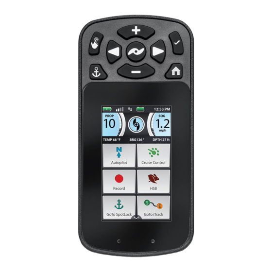
Page 6: Features
feaTURes i-PILOT® LINK™ REMOTE Screen Navigation Speed Up Prop On/Off Steer Left Steer Right Home Spot-Lock Talon Speed Down Header Dashboard Display Screen Content Area Info Boxes Touch Screen Active Area Charge Indicator Light i-PILOT® LINK™ CONTROL HEAD Control Head Pair Button Ulterra Ultrex™... -
Page 7: Remote Buttons
Spot-Lock Press to enable and disable Spot-Lock. WARNING The i-Pilot Link remote is equipped with a touch screen. Be aware of accidental or unintentional contact with the remote touch screen in order to avoid accidental motor operation. NOTICE: The remote is waterproof, but will not float. -
Page 8: Remote Navigation
The i-Pilot Link remote is equipped with a touch screen. Menus within the remote can be navigated using the buttons along the top of the remote, or by selecting options using the touch screen. Many of the menus with the i-Pilot Link system require the user to scroll up and down to view additional options in the Content Area. -
Page 9: Touch Screen And Control Buttons
REMOTE NAVIGATION TOUCH SCREEN AND CONTROL BUTTONS The i-Pilot Link remote can be controlled using the remote buttons, by utilizing the touch screen, or a combination of both. When using the remote buttons, the Screen Navigation button will scroll through options and the Ok button is used to select options. -
Page 10: The Options Menu And The System Menu
REMOTE NAVIGATION THE OPTIONS MENU AND THE SYSTEM MENU Become familiar with the Options Menu and the System Menu to easily navigate controls within the i-Pilot Link System. Options Menu System Menu The Options Menu is accessible by The System Menu is accessible by... -
Page 11: The Talon Menus
REMOTE NAVIGATION THE TALON MENUS Become familiar with the Talon menus to easily control the Talon(s) within the i-Pilot Link System. Talon Menu Talon Options Menu The Talon Menu is accessible by The Talon Options Menu is selecting the Talon Button from accessible by first selecting Talon the Home Screen. -
Page 12: Display Screen
GPS fix. Humminbird Connection Displays white arrows to show when the i-Pilot Link controller is communicating with the Humminbird. Grey arrows indicate that there is no communication. - Page 13 DISPLAY SCREEN INFO BOXES TEMP 72 °F BRG 359° DPTH 1 ft TEMP 72 °F BRG 359° DPTH 1 ft Bearing TEMP 72 °F BRG 359° DPTH 1 ft Temperature Bearing TEMP 72 °F BRG 359° DPTH 1 ft Bearing is the direction from the boat's current location to the target destination during navigation.
- Page 14 Left , Steer Right , Speed Up or Speed Down for Talon. In Standard Mode, Talon's Auto Deploy buttons changes the Display Screen to the i-Pilot Link will operate with maximum down-force with a Home Screen. complete Auto-Drive cycle of three hits spaced at three seconds apart.
- Page 15 Prop speed to 10. Double The Go To iTrack button is used to open a menu press to engage. Single press to disengage. used to navigate to an iTrack. The i-Pilot Link system will only bring up iTracks within a quarter Lock Keys mile range.
- Page 16 DISPLAY SCREEN TALON MENU BUTTONS i-Pilot Retracts the active Talon(s). Will be replaced by Select to return to the i-Pilot Link Menu. Pause as the action is taking place. Active Talon Down Allows the user to selects the active Talon and can Used to deploy the anchor.
- Page 17 Updates done from the remote are to update Right the remote. When in the Restore menu, press to Used to navigate to the right. Such as in restore the i-Pilot Link's factory settings. Spot-Lock Jog. Increase/Add Back Press to increase when making an adjustment Used to navigate back.
- Page 18 FR0007000002 iTrack - Start Follow Route- Start 100 ft Active Bands appear on the i-Pilot Link remote any time a navigational function is engaged. They are designed to tell more about how 100 ft Follow Route - Middle IT0000000006 FR0007000002 100 ft the system is functioning and display information to the user that is helpful in navigation.
- Page 19 DISPLAY SCREEN Sample Active Bands Become familiar with some of the active bands used on the i-pilot link remote interface. The Advanced AutoPilot Active The Spot-Lock Active Band The Go To Spot-Lock Active The Go To Waypoint Active Band appears when Advanced...
-
Page 20: Getting Started
Navigation i-Pilot Link uses GPS satellite signals as well as digital compass data to know where it is, where its heading and the direction the motor is pointing. Since i-Pilot Link depends on GPS satellite signals for navigation, a minimum GPS signal of one bar is required in order for GPS navigation controls to be enabled. -
Page 21: System Startup
Humminbird Customer Service at 1-800-633-1468. Depending on the shape of the Ethernet port on your Humminbird Fish finder, an additional ethernet adapter cable may be required for the installation. Refer to your Fish finder operations manual or see the i-Pilot Link Compatibility Chart on our Web site at minnkotamotors.com. -
Page 22: Power Up The I-Pilot Link System
The connectors are keyed to prevent reversed installation. Be careful not to force the connectors together. Locking Collar Route the i-Pilot Link Cable to the Ethernet port on Locking Collar the Humminbird or to an available Ethernet port on i-Pilot Link Cable i-Pilot Link Cable from the Ethernet Switch. - Page 23 Controls" section of this manual. remote including Speed Up , Speed Down Steer Left , Steer Right , and Prop On/Off After i-Pilot Link has obtained a minimum GPS signal strength of one bar, all remaining functions will become available. minnkotamotors.com | 23...
-
Page 24: Charging The Remote Battery
NOTICE: Minn Kota recommends only charging the i-Pilot Link remote with the charger provided USB Remote Charger Cable by Minn Kota. The Minn Kota charger is 5 volts DC, 2.1 amps. NOTICE: The USB end of the charging cable is not intended for prolonged exposure to saltwater environments. -
Page 25: Audio Modes
UNDERSTANDING AUDIO MODES The i-Pilot Link controller in the Control Head contains an internal speaker which can be configured to work in two different audio modes. The unit is factory set to Audio Mode 2. Review the modes below to determine what audio patterns are caused by conditions in each audio mode. -
Page 26: Audio Mode Control
AUDIO MODES AUDIO MODE CONTROL Changing the Controller Audio Mode Press the Home button. Scroll through the Content Area using either your 12:53 PM Spot-Lock iTrack PROP finger or the Screen Navigation button to find the Waypoint Waypoint TEMP 199 °F BRG 359°... -
Page 27: Spot-Lock
Spot-Lock location. If i-Pilot Link sees the motor is not positioned at the Spot-Lock location, it will control motor speed and direction in an attempt to keep the motor on the Spot-Lock. -
Page 28: Engaging Spot-Lock
The Save icon will disappear from the Active Band. NOTICE: 16 Spot-Lock locations are able to be recorded to memory when the i-Pilot Link system is not connected to a fish finder. When the system is connected to a fish finder, the number of Spot-Locks that can be saved is dependent on your fish finder. -
Page 29: Disengaging Spot-Lock
SPOT-LOCK Disengaging Spot-Lock With Spot-Lock engaged, press the Spot-Lock button on the remote to disengage Spot-Lock. The Spot-Lock Active Band will disappear from the Content Area. NOTICE: If your motor is equipped with a foot pedal, pressing any button on the foot pedal, or manually steering the motor with the foot pedal will disengage Spot-Lock. -
Page 30: Disengage Go To Spot-Lock
SPOT-LOCK The Spot-Lock Active Band will appear in the Content Area. The appearance of the Active Band will vary depending on the distance between the current location and the selected Spot-Lock. NOTICE: The Spot-Lock Active band will look similar to the appearance in image 2f on immediate right if the distance to the Spot-Lock is greater than 100 feet. -
Page 31: Spot-Lock Jog
SPOT-LOCK Spot-Lock Jog Spot-Lock Jog is a feature that is only available with a Heading Sensor. For information on the Heading Sensor, go to the "Heading Sensor" section of this manual. Spot-Lock Jog allows you to jog the Spot-Lock location 5 feet in the selected direction from the current Spot-Lock location. - Page 32 Heading Sensor. The Spot-Lock location can be jogged multiple times consecutively. Once the Spot-Lock location has been jogged, the i-Pilot Link navigational system will recognize the new Spot-Lock location, and i-Pilot will control the motor to move the boat accordingly.
-
Page 33: Waypoints
WaYPOINTs WORKING WITH WAYPOINTS Waypoints are saved latitude/longitude positions. They mark a position of interest such as your favorite fishing area, structure or marker buoy. Waypoints work similar to Spot-Locks. When i-Pilot navigates Waypoints, i-Pilot takes control over all steering functions; speed can be manually controlled or the Cruise Control function can also be used. -
Page 34: Mark A Waypoint
NOTICE: 16 Waypoints are able to be recorded to memory when the i-Pilot Link system is not connected to a fish finder. When the system is connected to a fish finder, the number of Waypoints that can be saved is dependent on your fish finder. -
Page 35: Disengage Go To Waypoint
WAYPOINTS A list of Waypoints that are within a quarter mile will appear. Scroll through the list of Waypoints to find a Waypoint to navigate to and select it. The Waypoint Active Band will appear in the Content Area. The appearance of the Active Band will vary depending on the distance between the current location and the selected Waypoint. -
Page 36: Cruise Control
LINK WITH CRUISE CONTROL During regular operation of the i-Pilot Link navigational system, the user can control prop speed. The controller will communicate the speed over ground to the remote and the remote will display it. The speed over ground is the speed that the boat is traveling and will vary based on environmental factors such as wind and current, even if the prop speed remains the same. -
Page 37: Engaging Cruise Control
CRUISE CONTROL WORKING WITH CRUISE CONTROL Engaging Cruise Control Press the Home button. Scroll through the Content Area using your finger or 12:53 PM Spot-Lock iTrack the Screen Navigation button to find the Cruise PROP Waypoint Waypoint TEMP 199 °F BRG 359°... -
Page 38: Disengage Cruise Control
CRUISE CONTROL Disengaging Cruise Control When Cruise Control is engaged, scroll through 1d 1c the Content Area using your finger or the 12:53 PM Spot-Lock iTrack Screen Navigation PROP button to find the Cruise Waypoint Waypoint TEMP 199 °F BRG 359° DPTH 9999 km Control button. -
Page 39: High Speed Bypass
HIGH sPeeD bYPass MOTOR SPEED AND HIGH SPEED BYPASS High Speed Bypass sets the Prop speed to Speed 10 when engaged and returns to the previously set speed when disengaged. The Prop Speed can be set to any speed, including Speed 0 to Speed 10 when High Speed Bypass is enagaged. WARNING Watch for a turning propeller when High Speed Bypass is engaged. -
Page 40: Engaging High Speed Bypass
HIGH SPEED BYPASS CONTROLLING HIGH SPEED BYPASS Engaging High Speed Bypass Press the Home button. 12:53 PM Scroll through the Content Area using your finger Spot-Lock iTrack PROP Waypoint Waypoint or the Screen Navigation TEMP 199 °F BRG 359° DPTH 9999 km button to find the HSB 12:53 PM Autopilot... -
Page 41: Autopilot
LINK WITH AUTOPILOT When in AutoPilot, i-Pilot Link keeps the trolling motor pointed in the direction you want to go. Each time the wind or water current moves the boat off course, AutoPilot senses the change and steers itself back to the original heading. The AutoPilot direction is set every time a steering change is made. -
Page 42: Engaging Legacy Autopilot Or Advanced Autopilot
AUTOPILOT WORKING WITH AUTOPILOT Engaging Legacy AutoPilot or Advanced AutoPilot Press the Home button. Scroll through the Content Area using your finger or 12:53 PM Spot-Lock iTrack the Screen Navigation PROP button to find the AutoPilot Waypoint Waypoint TEMP 199 °F BRG 359°... -
Page 43: Disengaging Legacy Autopilot Or Advanced Autopilot
AUTOPILOT Disengaging Legacy AutoPilot or Advanced AutoPilot When AutoPilot is engaged, scroll through the 12:53 PM Spot-Lock iTrack PROP Content Area using your finger or the Screen Waypoint Waypoint TEMP 199 °F BRG 359° DPTH 9999 km Navigation button to find the AutoPilot button. - Page 44 AUTOPILOT Once in the Options Menu, scroll through to find the AutoPilot Mode option, and select it. AutoPilot Mode The AutoPilot Mode options appear. Select either "Legacy" or "Advanced" Legacy Advanced . The circle to the right of the selected Legacy Advanced mode will be colored in green when selected.
-
Page 45: Itracks
UNDERSTANDING iTRACKS The i-Pilot Link system can be used to record sets of points that make up an iTrack. When recording an iTrack, i-Pilot starts to record GPS position data in the form of Track Points. The very first Track Point recorded is called the Start, and the last point recorded is called the End. -
Page 46: Recording An Itrack
TRACKS WORKING WITH ITRACKS Recording an iTrack Press the Home button. Scroll through the Content Area using your finger or 12:53 PM Spot-Lock iTrack PROP Waypoint Waypoint the Screen Navigation TEMP 199 °F BRG 359° DPTH 9999 km button to find the Record 12:53 PM Autopilot Cruise... -
Page 47: Go To A Saved Itrack
TRACKS Go To a Saved iTrack Manually navigate the boat to within a quarter mile of the saved iTrack. Press the Home button. 12:53 PM Spot-Lock iTrack PROP Scroll through the Content Area using your finger or Waypoint Waypoint TEMP 199 °F BRG 359°... -
Page 48: Disengage Go To Itrack
TRACKS Disengage Go To iTrack When Go To iTrack is engaged, scroll through the Content Area using either your finger or the Screen Navigation button to find the iTrack Active Band. Select the iTrack Active Band using your finger or by pressing the Ok button. -
Page 49: Circle Mode
30 to 500 feet. Circle Mode cannot be activated from the i-Pilot Link remote, but the direction of travel, radius of the circle can be adjusted, and the function can be disengaged using the i-Pilot Link remote. See the Humminbird manual to learn more about Circle Mode. -
Page 50: Change The Radius Of Circle Mode
CIRCLE MODE WORKING WITH CIRCLE MODE Change the Radius of Circle Mode When Circle Mode is engaged, scroll through the Content Area using either your finger or the Screen Navigation button to find the Circle Mode Active Band. Select the Circle Mode Active Band using your finger or by pressing the Ok button. -
Page 51: Disengage Circle Mode
CIRCLE MODE The direction of the Boat will reverse on the Circle Mode Active band. Disengage Circle Mode When Circle Mode is engaged, scroll through the Content Area using either your finger or the Screen Navigation button to find the Circle Mode Active Band. -
Page 52: Follow The Contour
The Offset from the contour can range from -300 to +300 feet. Follow the Contour cannot be activated from the i-Pilot Link remote, but the direction of travel, offset, and the function can be disengaged using the i-Pilot Link remote. See the Humminbird manual to learn more about Follow the Contour. -
Page 53: Change The Offset With Follow The Contour
FOLLOW THE CONTOUR WORKING WITH FOLLOW THE CONTOUR Change the Offset with Follow the Contour When Follow the Contour is engaged, scroll through the Content Area using either your finger or the Screen Navigation button to find the Follow the Contour Active Band. -
Page 54: Disengage Follow The Contour
FOLLOW THE CONTOUR Disengage Follow the Contour When Follow the Contour is engaged, scroll through the Content Area using either your finger or the Screen Navigation button to find the Follow the Contour Active Band. Select the Follow the Contour Active Band using your finger or by pressing the Ok button. -
Page 55: Routes
Humminbird. Navigating a Route cannot be activated from the i-Pilot Link remote, but the direction of travel can be changed, and the function can be disengaged using the i-Pilot Link remote. If you start another mode of i-Pilot navigation, navigating a Route will disengage automatically. -
Page 56: Reverse The Direction Of Route Navigation
ROUTES WORKING WITH ROUTES Reverse the Direction of Route Navigation When Route navigation is engaged, scroll through the Content Area using either your finger or the Screen Navigation button to find the Route Active Band. Select the Route Active Band using your finger or by pressing the Ok button. -
Page 57: Heading Sensor
The Minn Kota Heading Sensor provides boat heading information to a Bluetooth compatible i-Pilot or i-Pilot Link equipped Minn Kota motor. It contains a compass that senses the boat’s heading or orientation. The heading is used by the i-Pilot or i-Pilot Link system for navigation features such as Spot-Lock Jog. - Page 58 HEADING SENSOR The three LED patterns displayed by the Heading Sensor are: Power On - When the Heading Sensor is first connected to a power source, the LED will turn on for 3 seconds and then turn off. Pairing - The Heading Sensor can be paired with i-Pilot. While the Heading Sensor is attempting to pair, the LED will flash on and off twice per second for up to 20 seconds.
-
Page 59: Installation
HEADING SENSOR TOOLS AND RESOURCES REQUIRED • Drill • #2 Screwdriver • Awl or similar marking tool • 1/4” Drill Bit • 9/64” Drill Bit • Marine-grade Silicone INSTALLATION MOUNTING OPTIONS There are two options to install the Heading Sensor. Determine if the Power Cable for the Heading Sensor will pass below the mounting surface. - Page 60 HEADING SENSOR Position the sensor so that the arrow on the cover is Keel of Boat Arrow pointed toward the front of the boat in the direction to Front of travel. The arrow needs to be parallel with the keel Screw Holes of the boat.
- Page 61 HEADING SENSOR ITEM(S) NEEDED #1 x 2 Apply a marine-grade silicone caulk or sealant to both #8 - 18x1-1/2 screws (Item #1) as needed to Screw protect your boat from water damage. Using a #2 Screwdriver, mount the Heading Sensor Screw to the mounting location using the two screws.
- Page 62 HEADING SENSOR Double check the position of the Heading Sensor Screw so that the arrow on the cover is pointed toward the Arrow Holes to Front front of the boat in the direction of travel. The arrow needs to be parallel with the keel of the boat. Keel of Boat CAUTION...
- Page 63 HEADING SENSOR Using a #2 Screwdriver, mount the Heading Sensor to the mounting location using the two Screw screws. Hand tighten only. CAUTION Screw If the mounting surface is thin or made of a lightweight material, the mounting surface may need to be reinforced in order to support the Heading Sensor.
-
Page 64: Working With The Heading Sensor
Watch the Heading Sensor to be sure that once it successfully pairs that it starts emitting the LED pattern for normal operation. After the Heading Sensor is paired with i-Pilot or i-Pilot Link, proceed to Sensor Calibration and Sensor Offset. NOTICE: If battery power is lost, the Heading Sensor will not lose its Pairing to the i-Pilot System when it is powered down. -
Page 65: Heading Sensor Calibration
Heading Sensor Calibration The Heading Sensor calibration is initiated using either the i-Pilot or i-Pilot Link remote. Refer to the Owner’s Manual for your motor if you are unsure of the i-Pilot system that comes with your motor. The process of calibrating the Heading Sensor must occur while your boat is on the water. - Page 66 HEADING SENSOR On the i-Pilot Link remote, press the Home button. Scroll through the Content Area using either your 12:53 PM Spot-Lock iTrack PROP finger or the Screen Navigation button to find the Waypoint Waypoint TEMP 199 °F BRG 359°...
- Page 67 HEADING SENSOR The Circle on the right side of the display screen will show how the boat has progressed through the current circle and will fill in like a pie chart as the boat progresses. The left side of the Display Screen contains a counter that shows the number of complete circles that the boat has been driven and will increase from 0 to 1 and 2 as the circles are complete.
-
Page 68: Heading Offset
Offset will be a perfect 0° degrees. Knowing that installations are never perfect, the Heading Offset can be set on the i-Pilot Link remote to compensate for the difference between the two. Heading Offset has the ability to correct the difference in measurement in a range between +30°... - Page 69 HEADING SENSOR Once they are parallel, select the Set button. Start Once set, the Offset on the bottom right of the Display Screen will update. The Sensor Offset will automatically adjust. In the event of an error, correct the Offset to fit within the tolerance allowed. Press the Home button to exit the menu.
-
Page 70: Motor Controls
MOTOR CONTROls To Toggle the Prop Auto On Press the Home button. Scroll through the Content Area using either your 12:53 PM Spot-Lock iTrack finger or the Screen Navigation PROP button to find the Waypoint Waypoint TEMP 199 °F BRG 359° DPTH 9999 km Options button. -
Page 71: Adjusting Boat Scale
Boat Scale. For an installation where the motor thrust is oversized for the boat, decrease Boat Scale. Thrust requirements are determined by the size and weight of your boat. Minn Kota suggests selecting a trolling motor with at least 2 lbs. -
Page 72: Deploying The Motor
NOTICE: The Ulterra button can only be found in the Content Area with the Home Control Buttons on i-Pilot Link systems on an Ulterra motor. Certain Home Screen Buttons may be locked out while the motor is stowed because those functions require the motor to be deployed to operate. - Page 73 MOTOR CONTROLS 12:53 PM 12:53 PM Once in the Ulterra Menu, find the Deploy Stow Deploy button and select it. The Deploy button requires Stow Deploy a double press to engage. Motor Stowed Motor Deploying WARNING TEMP 199 °F BRG 359° DPTH 9999 km TEMP 199 °F BRG 359°...
-
Page 74: Stowing The Motor
Content Area with the Home Control Keypad Lock Spot-Lock iTrack Buttons on i-Pilot Link systems on an Ulterra motor. The motor can only be stowed when it is currently deployed. Once in the Ulterra Menu, find the Stow... -
Page 75: Adjusting The Trim
MOTOR CONTROLS To resume the Stow action, select the 12:53 PM 12:53 PM Stow button. Stow Deploy Motor Paused Motor Stowed If the Motor continues, it will complete the Stow process and normal motor operation will follow. TEMP 199 °F BRG 359°... - Page 76 MOTOR CONTROLS Once in the Ulterra Menu, find the Up button or Down Down button. Trimming up will raise the motor Down and trimming down will lower the motor. Find the button for the desired direction and select it. WARNING As soon as the Up button or Down button is...
-
Page 77: Change The Arrival Mode
Change the Arrival Mode The Arrival Mode is a setting that helps to control what i-Pilot Link does once certain navigation modes are complete. Arrival Mode affects Go To functions for iTracks, Waypoints and Routes. Arrival Mode also affects navigating Routes. The Arrival Mode will take over once the navigational feature has completed. - Page 78 MOTOR CONTROLS Once in the Options Menu, scroll through to find the Arrival Mode option, and select it. Arrival Mode Spot-Lock The Arrival Mode options appear. Select either Spot-Lock "Off" , "Spot-Lock" , "AutoPilot" AutoPilot Spot-Lock . Once the or "Talon Deploy" AutoPilot Deploy Talon Spot-Lock...
-
Page 79: Talon Controls
TEMP 73 °F BRG 359° DPTH 25 ft NOTICE: The Talon button can only be found in the Content Area with the Home Control Buttons on i-Pilot Link systems paired with a Autopilot Cruise Control Options System Talon. Select the Talon... - Page 80 BRG 359° DPTH 25 ft NOTICE: The Talon button can only be found in the Content Area with the Home Control Buttons on i-Pilot Link systems paired with a Autopilot Cruise Control Options System Talon. If the remote is already displaying the...
- Page 81 Talon while it is retracting to avoid the pinch point. NOTICE: Unless the Talon Control setting on the i-Pilot Link Remote is set to Right or Left, the remote will control both Talons when retracting. Be mindful of which Talon(s) is selected when retracting them.
- Page 82 TALON CONTROLS Toggle the Talon Anchor Mode Toggle the Anchor Mode on the i-Pilot Link Remote when the water or anchoring conditions change to fit your anchoring needs. Press the Home button. 12:53 PM Spot-Lock iTrack PROP Scroll through the Content Area using either your...
- Page 83 TALON CONTROLS Toggle the Work Light WARNING Work Light The Work Light on the Talon is not intended for navigational Talon purposes. The Work Light does not replace or act as a substitute for proper navigation lighting of your vessel. Failure to properly light your boat may cause harm or serious injury.
- Page 84 Talon Menu. Autopilot Cruise Control Options System NOTICE: When the i-Pilot Link System is paired with two Talons, toggling the Work Light Color on one Talon will toggle the Work Light Color on both. Ulterra Record Lock Keys Spot-Lock iTrack Once in the Talon Menu, find the Talon Work Light button, and select it.
- Page 85 Talon Menu. Autopilot Cruise Control Options System NOTICE: When the i-Pilot Link system is paired with two Talons, adjusting the Work Light Intensity on one Talon will adjust the Work Light Intensity Record Ulterra on both. Lock Keys Spot-Lock...
- Page 86 TALON CONTROLS Select the Active Talon When the i-Pilot Link System is paired to two Talons paired together, it is possible to control either the left or right Talon individually, or together. This is done from the Talon Menu. Press the Home button.
-
Page 87: Talon Options
Toggle the Auto-Retract Message The i-Pilot Link Remote will display a message when the Auto-Retract message feature is engaged and the boat is traveling above 5 mph when the Talon is at any percentage of deployment. The remote will not display a message about the Talon if it is deployed and the Auto-Retract is deselected, even if the boat exceeds 5 mph. - Page 88 TALON CONTROLS Adjust the Panel LED Brightness The brightness of the LED Panel on the Talon can be adjusted to account for ambient lighting conditions. There are three options for the LED panel brightness - low, medium and high. Press the Home button.
- Page 89 TALON CONTROLS Scroll through the Panel LED Menu and select one Left/Port of the three options, "Low" , "Medium" Left/Port Left/Port Right/Starboard or "High" Both Right/Starboard Right/Starboard Both Both The circle to the right of the selected option will be colored in green when selected.
- Page 90 TALON CONTROLS Once in the Talon Menu, find the Talon Options button, and select it. This opens the Talon Options menu. Once in the Talon Options Menu, scroll through to find the Manual Mode option. Manual Mode Prop Auto On In a single Talon installation, to toggle Aux Power, press the Manual Mode option.
- Page 91 TALON CONTROLS In a dual Talon installation, to toggle Manual Mode, press the Manual Mode option. This will Aux Power open a Manual Mode Menu. When the Manual Mode Menu opens, there will be a toggle for the "Left" and "Right" Talon. Select a Talon to put it into Manaul Mode.
- Page 92 TALON CONTROLS Reverse Talon Left/Right Installation The i-Pilot Link System recognizes the Port as the left Talon and the NOTICE: The Reverse L/R Talon option is only available Starboard as the right Talon. Use this setting in the event that you...
- Page 93 TALON CONTROLS Once in the Talon Menu, find the Talon Options button, and select it. This opens the Talon Options Menu. Once in the Talon Options Menu, scroll through to find the Reverse L/R Talon option. Manual Mode Prop Auto On A message about reversing the Talons will appear.
-
Page 94: Talon System
TALON CONTROLS TALON SYSTEM Toggle the Touch Screen The Touch Screen can be toggled from the Talon Menu. By default the Touch Screen is toggled "on". Press the Home button. 12:53 PM Spot-Lock iTrack PROP Scroll through the Content Area using either your finger or the Screen Navigation button to find the Talon... - Page 95 "off". To Edit the Talon Menu The i-Pilot Link remote allows the buttons in the Talon Menu to be rearranged. This allows the user to move favorites or frequently used buttons to the top of the menu. Press the Home button.
- Page 96 TALON CONTROLS Once in the Talon Menu, find the Talon System button, and select it. This opens the Talon System Menu. Once in the Talon System Menu, scroll through to find the Menu Edit button and select it. Menu Edit Once the Menu Edit button is selected, the Menu Edit...
- Page 97 TALON CONTROLS When done, select the Save button to keep the Save new arrangement, or select the Cancel button to Cancel return to the previous Talon Menu arrangement. minnkotamotors.com | 97 ©2019 Johnson Outdoors Marine Electronics, Inc.
-
Page 98: Remote Controls
ReMOTe CONTROls To Adjust the Backlight Press the Home button. Scroll through the Content Area using either your 12:53 PM Spot-Lock iTrack finger or the Screen Navigation PROP button to find the Waypoint Waypoint TEMP 199 °F BRG 359° DPTH 9999 km Options button. -
Page 99: To Adjust The Backlight Timeout
REMOTE CONTROLS To Adjust the Backlight Timeout Press the Home button. Scroll through the Content Area using either your 12:53 PM Spot-Lock iTrack finger or the Screen Navigation PROP button to find the Waypoint Waypoint TEMP 199 °F BRG 359° DPTH 9999 km Options button. -
Page 100: Restore System Defaults
REMOTE CONTROLS Restore System Defaults Press the Home button. Scroll through the Content Area using either your 12:53 PM Spot-Lock iTrack PROP finger or the Screen Navigation button to find the Waypoint Waypoint TEMP 199 °F BRG 359° DPTH 9999 km System button. -
Page 101: Selecting Remote Language
REMOTE CONTROLS Selecting Remote Language Press the Home button. Scroll through the Content Area using either your 12:53 PM Spot-Lock iTrack finger or the Screen Navigation PROP button to find the Waypoint Waypoint TEMP 199 °F BRG 359° DPTH 9999 km Options button. -
Page 102: Change The Depth Units
REMOTE CONTROLS Change the Depth Units Press the Home button. Scroll through the Content Area using either your 12:53 PM Spot-Lock iTrack finger or the Screen Navigation PROP button to find the Waypoint Waypoint TEMP 199 °F BRG 359° DPTH 9999 km Options button. -
Page 103: Change The Distance Units
REMOTE CONTROLS Change the Distance Units Press the Home button. Scroll through the Content Area using either your 12:53 PM Spot-Lock iTrack finger or the Screen Navigation PROP button to find the Waypoint Waypoint TEMP 199 °F BRG 359° DPTH 9999 km Options button. -
Page 104: Change The Speed Units
REMOTE CONTROLS Change the Speed Units Press the Home button. Scroll through the Content Area using either your 12:53 PM Spot-Lock iTrack PROP finger or the Screen Navigation button to find the Waypoint Waypoint TEMP 199 °F BRG 359° DPTH 9999 km Options button. -
Page 105: Change The Temperature Units
REMOTE CONTROLS Change the Temperature Units Press the Home button. Scroll through the Content Area using either your 12:53 PM Spot-Lock iTrack PROP finger or the Screen Navigation button to find the Waypoint Waypoint TEMP 199 °F BRG 359° DPTH 9999 km Options button. -
Page 106: Change The Time Format
REMOTE CONTROLS Change the Time Format Press the Home button. Scroll through the Content Area using either your 12:53 PM Spot-Lock iTrack finger or the Screen Navigation PROP button to find the Waypoint Waypoint TEMP 199 °F BRG 359° DPTH 9999 km Options button. -
Page 107: Change The Time Zone
REMOTE CONTROLS Change the Time Zone Press the Home button. Scroll through the Content Area using either your 12:53 PM Spot-Lock iTrack finger or the Screen Navigation PROP button to find the Waypoint Waypoint TEMP 199 °F BRG 359° DPTH 9999 km Options button. -
Page 108: Toggle Daylight Savings
REMOTE CONTROLS Toggle Daylight Savings Press the Home button. Scroll through the Content Area using either your 12:53 PM Spot-Lock iTrack finger or the Screen Navigation PROP button to find the Waypoint Waypoint TEMP 199 °F BRG 359° DPTH 9999 km Options button. -
Page 109: Change The Go To List Sort Order
REMOTE CONTROLS Change the Go To List Sort Order Press the Home button. Scroll through the Content Area using either your 12:53 PM Spot-Lock iTrack finger or the Screen Navigation PROP button to find the Waypoint Waypoint TEMP 199 °F BRG 359°... -
Page 110: Set The Remote Auto Off
REMOTE CONTROLS Set the Remote Auto Off The Remote is factor set to turn off after it stops receiving input from the buttons or the touch screen after a certain length of time. The Auto Off setting lets the operator determine how long the remote will stay on before the remote will power off. WARNING When the motor is being controlled by the i-Pilot system, the Control Head will continue to perform the last task it was assigned, even when the remote is not powered "on". -
Page 111: To Lock The Remote
REMOTE CONTROLS Once in the Options Menu, scroll through to find the Auto Off option, and select it. Auto O The Auto Off options will appear. Scroll through and find the desired Auto Off option and select it. The options include "15 Minutes" "30 Minutes"... -
Page 112: To Unlock The Remote
To Rotate the Touch Screen If you prefer the remote buttons to be orientated below the touch screen, the i-Pilot Link remote has the option to orientate the screen to accommodate this preference. Once you orientate the screen, you can hold the remote with the buttons below the touch screen and the screen will be right reading. -
Page 113: To Toggle The Touch Screen
REMOTE CONTROLS Once in the Options Menu, scroll through to find the Screen Rotate option. By default, the Screen Rotate Prop Auto On Screen Rotate is toggled "off". To toggle Screen Rotate "on", press the Screen Rotate option. The Screen Rotate toggle Screen Rotate Prop Auto On will turn green to indicate Screen Rotate on is turned... -
Page 114: To Edit The Home Screen Button Menu
"off". To Edit the Home Screen Button Menu The i-Pilot Link remote allows the buttons in the Home Screen menu to be rearranged. This allows the user to move favorites or frequently used buttons to the top of the menu. - Page 115 REMOTE CONTROLS Once in the System Menu, scroll through to find the Menu Edit option and select it. Menu Edit Once the Menu Edit is selected, the display screen will return to the Home Screen Buttons and display the on-screen prompt to "Select icon to move". Select the desired icon to move.
-
Page 116: I-Pilot Link App
Specifications subject to change without notice. This diagram is for reference only and may differ from your actual app interface. i-Pilot Link app will only work with i-Pilot Link enabled motors. Be sure that you download the correct app as other Minn Kota apps will not work with your motor. - Page 117 The App Update Indicator is only available when an update to the app is available. This icon will not appear when the app is up-to-date. This icon is for updates to the app only. For updates to the controller, refer to the "i-Pilot Link Software Update"...
- Page 118 WARNING The person operating the i-Pilot Link app is under the same responsibility of operation as if they were operating the i-Pilot Link either through the remote or any other manner. All safety considerations and precautions for motor operation must be heeded and abide by.
-
Page 119: Launching The App & Demo Mode
-PILOT LINK APP LAUNCHING THE APP & DEMO MODE Launching the app when it is not paired with the motor will allow you to try it out. Every time the app is launched, you must agree with the disclaimer in order to continue. Become familiar with the app screens in order to understand how to operate your motor with the app. -
Page 120: Getting Started
On the device you intend to pair with the i-Pilot Link controller, turn Bluetooth "on". Control Head - Ultrex, Locate the Pair button on the top of your Control Terrova &... -
Page 121: Update The I-Pilot Link App
Update the i-Pilot Link App NOTICE: It is important to keep the i-Pilot Link App up-to-date, because all updates to the i-Pilot Link remote and controller are communicated through the app. Open the i-Pilot Link app on the device. Check to see if the App Update Indicator icon in the upper right hand corner is present. -
Page 122: Check Remote And Controller Software Version
Check Remote and Controller Software Version The i-Pilot Link App on the device communicates with the i-Pilot Link controller, which is in the Control Head of the paired motor. When the App is communicating with a controller, the About screen will display the current version of the app and information about the versions of software in the controller. -
Page 123: Update The I-Pilot Link Controller
To update the app, the controller, using the remote. Complete any remote please refer to the "Update the i-Pilot Link App" section of this updates after all other updates have been complete. To manual. -
Page 124: Service & Maintenance
seRVICe & MaINTeNaNCe To Open the Diagnostics Screen When opening the About Screen, the screen will display information on the Battery, Motor Heading and Heading Sensor. Press the Home button. Scroll through the Content Area using either your 12:53 PM Spot-Lock iTrack PROP... -
Page 125: I-Pilot Link Software
LINK SOFTWARE CHECKING & UPDATING SOFTWARE To Open the About Screen When opening the About Screen, the screen will display the i-Pilot Link Remote and controller software version. Press the Home button. Scroll through the Content Area using either your... -
Page 126: Update I-Pilot Link Remote Software
SERVICE & MAINTENANCE Update i-Pilot Link Remote Software Be sure that the software in the Controller is updated before updating the remote. Please see the "i-Pilot Link App" section of this manual on how to update the Controller. NOTICE: The software update for the remote will come from the Control Head. -
Page 127: Pairing A Remote With A Controller
PAIRING A REMOTE An i-Pilot Link controller may pair up to 3 remotes. These three remotes can be a combination of standard i-Pilot Link remotes and Micro remotes. Any additional remotes can be paired using the following steps. Once the maximum number of remotes have been paired, the controller will start replacing a new remote with the oldest paired remote in memory. -
Page 128: Talon Control
Pairing i-Pilot Link with Two Talons In order for the i-Pilot Link system to be paired to two Talons, the Talons first need to be paired together. To learn how to pair two Talons together, read the "Pairing Two Talons and Programming the Mounting Location" section of the Talon Manual. Once the Talons are paired together, follow the directions for "Pairing i-Pilot Link to a Single Talon". - Page 129 SERVICE & MAINTENANCE Check Talon Software Version Look up the version of software installed on the Talon. The i-Pilot Link System will display the software version for one or two Talons that are paired to the system. Press the Home button.
- Page 130 Left/Port position. To Forget Paired Talons It may be necessary to forget any Talons that are paired to the i-Pilot Link system. To forget Talon(s) follow the steps below. Press the Home button.
- Page 131 WARNING You will need to pair with your BT Talon if you want to reconnect this device. Carefully read the warning and select the Confirm button. The i-Pilot Link System will then forget Conf irm the Talon(s). minnkotamotors.com | 131...
-
Page 132: General Maintenance
SERVICE & MAINTENANCE GENERAL MAINTENANCE • Connect the motor to a power source to power up the control head before use. • Check the remote batteries each time the remote is powered up. • Inspect the Remote and Control Head before each use to make sure that they are not obstructed. Having a clear view from the Control Head to the sky and an unobstructed sight line between the Remote and Control Head will allow for proper communication. -
Page 133: For Further Troubleshooting & Repair
Authorized Service Centers Minn Kota has over 800 authorized service providers in the United States and Canada where you can purchase parts or get your products repaired. Please visit our Authorized Service Center page on our website to locate a service provider in your area. -
Page 134: Compliance Statements
Minn Kota motors are not subject to the disposal regulations EAG-VO (electric devices directive) that implements the WEEE directive. Nevertheless never dispose of your Minn Kota motor in a garbage bin but at the proper place of collection of your local town council. - Page 135 • Maximum RF power transmitted: +10 dBm TRADEMARKS Minn Kota®, Riptide®, i-Pilot®, AutoPilot™, CoPilot™, Link™, PowerDrive™, Terrova™, Ulterra™, Ultrex™ are trademarked by or registered trademarks of Johnson Outdoors Marine Electronics, Inc. The Bluetooth® word mark and logos are registered trademarks owned by Bluetooth SIG, Inc. and any use of such marks by Johnson Outdoors Inc is under license.
-
Page 136: Parts Diagram & Parts List
TERROVA, RIPTIDE TERROVA, ULTERRA, RIPTIDE ULTERRA & ULTREX The parts diagram and parts list provides Minn Kota® WEEE compliance disassembly instructions. For more information about where you should dispose of your waste equipment for recycling and recovery and/or your European Union member state requirements, please contact your dealer or distributor from which your product was purchased. - Page 137 PARTS DIAGRAM & PARTS LIST Remote & Heading Sensor Parts List Assembly Part # Description Notes Quantity 2994076 REMOTE ASY, LINK TOUCHSCRN 2996400 HEADING SENSOR ASSEMBLY Item Part # Description Notes Quantity 2383442 SCREW-3MM X .5 PPH MACHINE 2383471 SCREW-M2 X 7MM SS DELTA PT 2390200 DUST CAP, LINK TOUCH REMOTE 2390210...
- Page 138 PARTS DIAGRAM & PARTS LIST i-PILOT LINK CONTROL HEAD Control Head Parts Diagram Ultrex, Terrova & Riptide Terrova Ulterra & Riptide Ulterra 138 | minnkotamotors.com ©2019 Johnson Outdoors Marine Electronics, Inc.
- Page 139 PARTS DIAGRAM & PARTS LIST Control Head Parts List Assembly Part # Description Notes Quantity 2770234 COVER KIT, IPLT 3.0 TRV,ULTREX *FRESHWATER* *TERROVA* *ULTREX* 2770236 COVER KIT, IPLT 3.0 RT TERROVA *SALTWATER* *RIPTIDE TERROVA* 2774177 MOTOR KIT, IPLT 3.0 TRV,ULTREX *FRESHWATER* *TERROVA* *ULTREX* *ELECTRONICS &...
- Page 140 Stop buying new batteries and start taking care of the ones you’ve got. Many chargers can actually damage your battery over time – creating shorter run times and shorter overall life. Digitally controlled Minn Kota chargers are designed to provide the fastest charge that protect and extend battery life.
Need help?
Do you have a question about the i-Pilot Link and is the answer not in the manual?
Questions and answers
My remote won’t take a charge’ second one I’ve had, hope I don’t have to buy another
How can I keep the trolling motor on a spot that im fishing