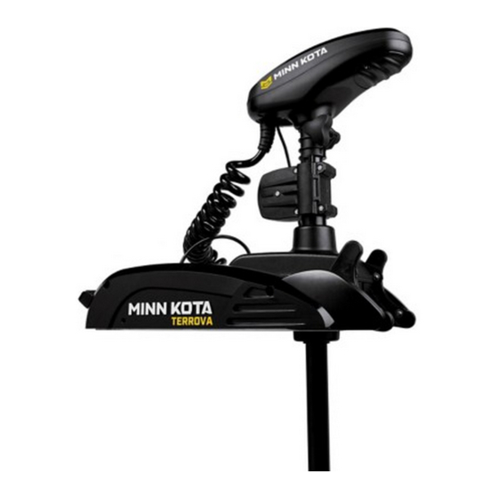
MINN KOTA i-Pilot Link User Manual
Integrated wireless gps trolling system
Hide thumbs
Also See for i-Pilot Link:
- Owner's manual (140 pages) ,
- User manual (72 pages) ,
- Installation manual (13 pages)
Advertisement
Table of Contents
Advertisement
Table of Contents

Subscribe to Our Youtube Channel
Summary of Contents for MINN KOTA i-Pilot Link
- Page 1 INTEGRATED WIRELESS GPS TROLLING SYSTEM USER MANUAL...
- Page 2 Introduction ........................Warranty and Warnings ....................Installation ........................Parts list ..........................Preparing for Installation ......................Installation of i-Pilot link Controller ..................Verifying Installation ....................... Getting Started ......................... Knowing Your Remote ......................Knowing Your i-Pilot link Controller ..................system startup ........................
- Page 3 Safety and Cautions while using Link You are responsible for the safe and prudent operation of your vessel. We have designed i-Pilot link to be an accurate and reliable tool that will enhance boat operation and improve your ability to catch fish. This product does not relieve you from the responsibility for safe operation of your boat.
- Page 4 Center or factory, labor to haul out, remove, re-install or re-rig products removed for warranty service, or any other similar items are the sole and exclusive responsibility of the purchaser. i-Pilot link systems purchased outside of the u.s. (or parts of such systems) must be returned prepaid with proof of purchase (including the date of purchase and serial number) to any authorized Minn Kota service Center in the country of purchase.
- Page 5 HuMMInbIRd WaRnInGs WaRnInG! This device should not be used as a navigational aid to prevent collision, grounding, boat damage, or personal injury. When the boat is moving, water depth may change too quickly to allow time for you to react. always operate the boat at very slow speeds if you suspect shallow water or submerged objects.
- Page 6 X 5/8 THd* (ss 2370817 lanYaRd,RMT w/CaRabeeneR 2224704 InseRT-PluG, blK, i-PIloT lInK 2376312 TIe WRaP,blaCK,uV ResIsT. nYlon 2994909 baG assY, i-PIloT lInK, PoWeR 2373241 Cable, usb ReMoTe CHaRGeR 2375900 adaPTeR, usb PoWeR PoRT 2377156 Manual-Cd, i-PIloT lInK 2377155 Manual QCK Ref, i-PIloT lInK...
- Page 7 PaCK 2374637 o-RInG, baTTeRY seal 2376421 dooR, baTTeRY 2383442 sCReW-3MM X .5 PPH MaCHIne 2994908 baG assY, i-PIloT lInK, V2 2372100 sCReW-#8-18 X 5/8 THd* (ss 2370817 lanYaRd,RMT w/CaRabeeneR 2376716 PluG, sTRaIn RelIef V2/sP 2332104 sCReW-1/4-20 X 5/8 s/s 2376312 TIe WRaP,blaCK,uV ResIsT.
-
Page 8: Preparing For Installation
To help with future service work or ordering replacement parts, please refer to the information box in the notes section located on the back pages of this manual. before installing i-Pilot link on your motor, make sure the trolling motor is properly installed on your boat. find a clean and dry location for performing the installation. - Page 9 * i-Pilot Link will override all CoPilot functionality. CoPilot remotes will not function with i-Pilot Link. * The Terrova foot pedal is fully functional and supported when i-Pilot Link is installed correctly. 1. Remove all power to the trolling motor.
- Page 10 5. Route the ethernet cable through the grommet hole and through the center of the coil cord. (figure 5) 6. Plug the i-Pilot link controller connector into the accessory connector as shown. (figure 6) be careful to orient connector properly prior to pushing together. The plug will click twice when pushing it together and the yellow end will be fully covered when installed properly.
- Page 11 8. Place the i-Pilot link controller where the control box cover was installed and secure with supplied #8 screws. do not over tighten screws. (figure 9) 9. i-Pilot link is now installed on the motor. skip ahead to page 22 to verify the installation. FIGURE 8 FIGURE 9 mi nn kot a m ot or s .
- Page 12 INSTALLATION i-Pilot Link Installation on PowerDrive V2 and Riptide SP *Note: Once i-Pilot Link is installed in a PowerDrive V2 or Riptide SP motor, the foot pedal cannot be used again unless i-Pilot Link is fully uninstalled. 1. Remove all power to the trolling motor FIGURE 10 2.
- Page 13 INSTALLATION 4. If the trolling motor has AutoPilot, it must be removed as follows: a. disconnect all six AutoPilot connectors from AutoPilot controller, using a needle-nose pliers and a utility knife to remove any heat shrink insulation that may exist. (figure 13) b.
- Page 14 Sonar Ground b. The motor power wires must be routed as shown. Wire (figure 16) 7. Route the i-Pilot link controller cable through the grommet hole and through the center of the coil cord (figure 17). Power Wires AutoPilot Wires...
- Page 15 IMPORTANT: Pull on each wire to make sure it is secured properly. Loose wires can cause damage to i-Pilot Link Controller and the entire motor. FIGURE 18 Insert AutoPilot wires into terminal holders. AutoPilot connectors must be placed onto holders exactly as shown.
- Page 16 INSTALLATION 9. Install new grommet supplied with i-Pilot link by snapping it into the hole located in front of the coil cord strain relief. The i-Pilot link controller cable must be placed in the pass-through slot of the grommet. (figure 22) 10.
- Page 17 INSTALLATION 14. Remove center housing by pushing in on both sides and lifting up at the same time. This will expose the main control board and wiring. (figure 27) 15. The steering motor cable passes through the top of the center housing removed in step 14.
- Page 18 (figure 29) 17. Tighten the cable strain relief as shown. The i-Pilot link controller steering cable should slide freely through the strain relief when installed properly. (figures 30 and 31)


Need help?
Do you have a question about the i-Pilot Link and is the answer not in the manual?
Questions and answers