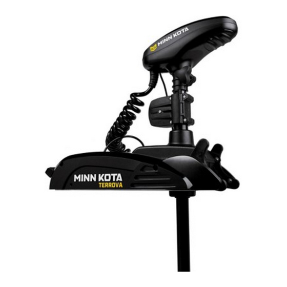
MINN KOTA i-Pilot Link Installation Manual
For trolling motors
Hide thumbs
Also See for i-Pilot Link:
- Owner's manual (140 pages) ,
- User manual (72 pages) ,
- Specifications (5 pages)
Advertisement
Quick Links
Advertisement

Subscribe to Our Youtube Channel
Summary of Contents for MINN KOTA i-Pilot Link
- Page 1 InstallatIon GuIde...
- Page 2 X 5/8 tHd* (ss 2370817 LaNYard,rMt w/CaraBINer 2224704 INsert-PLUG, BLK, i-PILot LINK 2376312 tIe wraP,BLaCK,Uv resIst.NYLoN 2994909 BaG assY, i-PILot LINK, Power 2373241 CaBLe, UsB reMote CHarGer 2375900 adaPter, UsB Power Port 2377156 MaNUaL-Cd, i-PILot LINK 2377155 MaNUaL QCK reF, i-PILot LINK...
- Page 3 BatterY, LIPo PaCK 2374637 o-rING, BatterY seaL 2376421 door, BatterY 2383442 sCrew-3MM X .5 PPH MaCHINe 2994908 BaG assY, i-PILot LINK, v2 2372100 sCrew-#8-18 X 5/8 tHd* (ss 2370817 LaNYard,rMt w/CaraBINer 2376716 PLUG, straIN reLIeF v2/sP 2332104 sCrew-1/4-20 X 5/8 s/s 2376312 tIe wraP,BLaCK,Uv resIst.NYLoN...
- Page 4 FIGUre 3 read through the entire installation process before performing the installation. If you need help or need further instruction on installing i-Pilot Link, please call Minn Kota technical service at 1-800-227-6433 to talk to a customer service representative. Humminbird Fishfinder Depending on your Humminbird model and system configuration, you may need to pur- chase additional cables, as shown below.
- Page 5 (Figure 9) when pushing it together and the yellow 9. i-Pilot Link is now installed on the mo- end will be fully covered when installed tor. skip ahead to page 22 to verify the properly.
- Page 6 4. If the trolling motor has AutoPilot, it PowerDrive V2 & Riptide SP must be removed as follows: *Note: once i-Pilot Link is installed in a Pow- a. disconnect all six AutoPilot erdrive v2 or riptide sP motor, the foot pedal...
- Page 7 Link Controller and the en- (Figure 16) AutoPilot wires tire motor. (AutoPilot Motors only) 7. route the i-Pilot Link control- AutoPilot connectors must be ler cable through the grommet placed onto holders exactly as hole and through the center of shown.
- Page 8 INSTALLATION GuIde 9. Install new grommet supplied with 14. remove center housing by pushing in i-Pilot Link by snapping it into the hole on both sides and lifting up at the same located in front of the coil cord strain time.
- Page 9 16. Loosen the cable strain relief that 18. slide four pieces of heat is secured to the base of the motor shrink insulation over and install the i-Pilot Link controller each side of the wires steering cable into the open strain that were disconnected relief slot.
- Page 10 HEAT SHRINK! connector. FIGUre 33 21. reinstall center hous- 25. i-Pilot Link is now installed ing over control board on the motor. skip ahead by pushing it down until to the next section to the side fingers lock into verify the installation.
- Page 11 The i-Pilot Link can be connected directly to the Humminbird Fishfinder or to the It is important to verify your i-Pilot Link installation prior to going on the water. If this Humminbird ethernet switch (optional). If you purchase the ethernet switch, install it cannot be done, it is highly recommended that system verification be done in an open using the instructions in the ethernet accessory Guide.
- Page 12 All equipment should be connected and powered before you turn on the Fishfinder. when the i-Pilot Link is detected, i-Pilot Link Connected will display briefly on the screen. You can also confirm the installation connections using the following instructions.
- Page 13 Consumer & Technical Service Johnson Outdoors Marine Electronics, Inc. PO Box 8129 121 Power Drive Mankato, MN 56001 Phone (800) 227-6433 Fax (800) 527-4464 minnkotamotors.com A Johnson Outdoors Company ©2012 Johnson Outdoors Marine Electroincs, Inc. All rights reserved. Conforms to 89/336/EEC (EMC) under standards EN 55022A, EN 50082-2 since 1996 LN V9677264 WARNING: This product contains chemical(s) known to the state of California to cause cancer and/or reproductive toxicity.


Need help?
Do you have a question about the i-Pilot Link and is the answer not in the manual?
Questions and answers