Mitsubishi Electric AE-200A Instruction Book
Air conditioning control system
Hide thumbs
Also See for AE-200A:
- Instruction book (192 pages) ,
- Service handbook (108 pages) ,
- Installation manual (40 pages)
Table of Contents
Advertisement
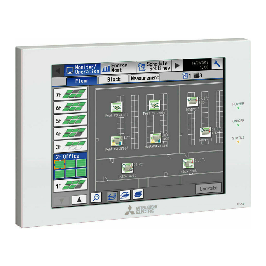
Air Conditioning Control System
Centralized Controller
AE-200A/AE-50A
AE-200E/AE-50E
Before installing the controller, please read this Instruction Book carefully to ensure proper operation.
Retain this manual for future reference.
Contents
1. Safety precautions ..............................................................2
1-1. General precautions ...................................................................2
1-2. Precautions for relocating or repairing the unit ...........................3
1-3. Additional precautions .................................................................3
2. Introduction .........................................................................4
2-1. Terms used in this manual ..........................................................4
2-2. Required licenses .......................................................................4
2-3. "Group" and "Block" definitions ...................................................4
2-4. Main and Sub system controllers (M-NET) .................................5
2-5. Controller interface .....................................................................6
2-6. Number of connectable units ......................................................7
2-7. Product features .........................................................................7
3. Basic operations ...............................................................10
3-1. Monitor/Operation .....................................................................10
3-2. Energy Management ................................................................27
3-3. Schedule ...................................................................................36
3-4. Status List .................................................................................48
3-5. Malfunction Log ........................................................................51
3-6. Error code list ............................................................................52
4. Practical operations ..........................................................55
4-1. Maintenance .............................................................................55
5. Initial startup settings ........................................................61
5-1. Initial startup setting procedures ...............................................61
5-2. Initial Settings ...........................................................................66
5-3. Function1 ..................................................................................91
5-4. Function2 ..................................................................................94
5-5. User Information .......................................................................99
6. Maintenance ...................................................................102
6-1. Backing up settings data .........................................................102
6-2. Importing settings data ...........................................................103
6-3. Software Update .....................................................................104
7. Specifications ..................................................................105
Instruction Book
Ver. 7.10
Advertisement
Table of Contents

Related Manuals for Mitsubishi Electric AE-200A


Summary of Contents for Mitsubishi Electric AE-200A
-
Page 1: Table Of Contents
Air Conditioning Control System Centralized Controller AE-200A/AE-50A AE-200E/AE-50E Instruction Book Contents 1. Safety precautions ..............2 1-1. General precautions ..............2 1-2. Precautions for relocating or repairing the unit ......3 1-3. Additional precautions ..............3 2. Introduction .................4 2-1. Terms used in this manual ............4 2-2. -
Page 2: Safety Precautions
1. Safety precautions ►Thoroughly read the following safety precautions prior to installation. ►Observe these precautions carefully to ensure safety. ►After reading this manual, pass the manual on to the end user to retain for future reference. ►The user should keep this manual for future reference and refer to it as necessary. This manual should be made available to those who repair or relocate the units. -
Page 3: Precautions For Relocating Or Repairing The Unit
To reduce the risk of injury, electric shock, or malfunction, avoid contact with the sharp edges of certain parts. Consult your dealer for the proper disposal of the controller. Improper disposal will pose a risk of environmental pollution. 1-2. Precautions for relocating or repairing the unit The controller must be repaired or moved only by qualified personnel. -
Page 4: Introduction
Any connected air conditioning systems can be operated or monitored on the AE-200A/AE-50A/AE-200E/AE-50E’s LCD or the Web browser. Each AE-200A/AE-50A/AE-200E/AE-50E can control up to a total of 50 indoor units and other equipment. By connecting AE-200A/AE-200E (main controller) and AE-50A/AE-50E (sub controllers), up to 200 indoor units and other equipment can be controlled. -
Page 5: Main And Sub System Controllers (M-Net)
2-4. Main and Sub system controllers (M-NET) Each group can be controlled by a Main system controller or a Sub system controller. AE-200/AE-50 is exclusively for use as a Main system controller and cannot be used as a Sub system controller. Main system controller Main system controller refers to a system controller that controls all other system controllers including the units they control. -
Page 6: Controller Interface
2-5. Controller interface Important ● Before using the controller, remove the protective sheet on the cover to avoid the sheet from sticking to the touch panel and causing malfunctions. ● Use the supplied L-shaped driver to remove or attach the cover. Power LAN1 USB port... -
Page 7: Number Of Connectable Units
(2 speeds) can be changed. Schedule (Available/Not Avail.) The scheduled operations can be enabled or disabled. Operation Hold (AE-200A/AE-50A only) The Hold function can be enabled or disabled. Prohibition of local remote Some operations or settings from the local remote controllers can be controller operation prohibited. - Page 8 System View and indoor units) can be checked. The following settings can be made: [Time Master/Sub], [Schedule: Advanced Season setting], [Hold type] (AE-200A/AE-50A only), and [Old model compatibility mode]. AI and PI controllers, temperature sensor, humidity sensor, and Function1 Measurement metering device can be registered.
- Page 9 Function Description Backing up settings data The settings data can be stored to a USB memory device. Backed-up settings data can be restored from a USB memory Importing settings data device. The operation data, such as apportioning parameters and power Maintenance CSV output consumption, can be output to a USB memory device.
-
Page 10: Basic Operations
3. Basic operations 3-1. Monitor/Operation This section explains how to monitor and operate the unit groups. 3-1-1. Screen sequence [Floor] display (zoomed-in) [Floor] display (zoomed-out) Touch [ Touch [ Select a group and touch [Operate]. Touch [Floor]. Touch [Block]. Touch [OK] or [Block] display Operation settings screen [Cancel]. - Page 11 *11 The “Starting up” icon will stay when the unit cannot be recognized after startup. Check for proper connection of the air conditioning unit and proper group settings. *12 The Hold function can be used on the AE-200A/AE-50A, but not on the AE-200E/AE-50E. [2] LOSSNAY unit (ventilator) group...
- Page 12 [3] Air To Water (PWFY) unit group and HWHP (CAHV) unit group Error Schedule set Schedule disabled Water temperature Energy-saving ON HOLD ON display *1 The “Energy-saving ON” icon will appear while the Peak Cut control is performed on the Air To Water (PWFY) unit group. This icon will not appear for the HWHP (CAHV) unit groups.
- Page 13 3-1-3. Checking the operation conditions This section explains how to display the operation conditions of units. [1] [Floor] display Touch [Monitor/Operation] in the menu bar, and then touch [Floor]. Note: The unit groups that are under the control of both AE-200 and AE-50 can be displayed. Weekly schedule number Floor selection Number of units in error...
- Page 14 Item Description Floor selection Select a floor you want to monitor. Area selection Select an area of the selected floor you want to monitor. Group name The name of the group will appear. Indoor unit return air temperature will appear. Note: The temperature shown may be different from the actual room temperature.
- Page 15 [2] [Block] display Touch [Monitor/Operation] in the menu bar, and then touch [Block]. Weekly schedule number Block name Number of units in error Block selection Group icons The icon indicates the Number of units whose operation condition of the filter sign is turned on group.
- Page 16 [3] [Measurement] display Touch [Monitor/Operation] in the menu bar, and then touch [Measurement]. The measurement data of the temperature sensors, humidity sensors, and metering devices will appear. Note: Measurement settings on the [Measurement] screen under the [Function1] menu are required to display the measurement data on this screen.
- Page 17 [4] [HWHP] display Touch [Monitor/Operation] in the menu bar, and then touch [HWHP]. The operation status of each HWHP (CAHV) unit group will appear. Note: The [Controller] setting will appear when the [System Exp] setting on the [Unit Info.] screen is set to [Expand]. Switch the [Controller] setting between [AE200], [AE1], [AE2], and [AE3] to display the information for each AE-200 and AE-50 individually.
- Page 18 [5] [AHC] display Touch [Monitor/Operation] in the menu bar, and then touch [AHC]. The status of input and output ports of each Advanced HVAC CONTROLLER (AHC) can be monitored. Note: The [Controller] setting will appear when the [System Exp] setting on the [Unit Info.] screen is set to [Expand]. Switch the [Controller] setting between [AE200], [AE1], [AE2], and [AE3] to display the information for each AE-200 and AE-50 individually.
- Page 19 Item Description The number of units that are currently in error will appear. Touching “ ” will bring up the Number of units in error [Malfunction] screen. (See section 3-4-1 “Malfunction List”.) *1 The item will not appear if the number of units is “0.” WT07190X01...
- Page 20 3-1-4. Selecting the icons of the groups to be operated On the [Floor] or [Block] display under the [Monitor/Operation] menu, select the icon(s) of the group(s) to be operated as explained below, and then touch [Operate] to bring up the operation settings screen. [1] Selecting group icons (1) Selecting a group On the [Floor] or [Block] display, touch the icon(s) of the...
- Page 21 (4) Selecting all groups in the selected block On the [Block] display, touch the block(s) you want to Block icon operate. The selected block and group icons will appear with an orange frame. Touch again to deselect. To cancel all group selections, touch the “Deselect-all” button.
- Page 22 3-1-5. Operation settings screen On the screen under the [Monitor/Operation] menu, selecting the group icon and touching [Operate] will bring up the operation settings screen for the selected group. The current operation conditions will appear. Change necessary operation settings, and then touch [OK] to save the settings. Touch [Cancel] to return to the previous screen without making any changes.
- Page 23 [2] LOSSNAY unit group Refer to section 3-1-6 for details about the setting items. Floor name or block name Group icon Group name ON/OFF Ventilation mode Prohibit Remote Controller Filter Sign Cancel Touch to return to the Schedule previous screen without making any changes.
- Page 24 [4] HWHP (CAHV) unit group Refer to section 3-1-6 for details about the setting items. Group icon Group name Set temperature ON/OFF Operation mode Fan Mode Prohibit Remote Controller Cancel Touch to return to the Schedule previous screen without making any changes. Hold Touch to reflect the changes made.
- Page 25 Operation mode HWHP (CAHV) unit: Heating, Heating ECO, Hot Water, Anti-freeze Note: Only the operation modes available for the unit model will appear. Note: The Setback mode can be selected on the AE-200A/AE-50A, but not on the AE-200E/AE-50E. Touch to adjust the set temperature.
- Page 26 Note: [Hold type] can be specified on the [Advanced] screen. Note: The Hold function can be used on the AE-200A/AE-50A, but not on the AE-200E/AE-50E. Touch [Reset] to switch between resetting and not resetting the filter sign after cleaning the filter.
-
Page 27: Energy Management
3-2. Energy Management 3-2-1. Energy Use Status On the [Energy Use Status] screen, the energy-control-related status, such as electric energy consumption, operation time, and outdoor temperature, can be displayed in a graph. Operators can check the detailed status of given indoor units by specifying the date to display the data per group, block, or unit address. Also, the status of other indoor units can be displayed at the same time for comparison. - Page 28 Item Description Select [AE200] to display the data for AE-200, and select [AE1], [AE2], or [AE3] to display the Controller data for each AE-50. Select a block name, group name, or address number to display its data. Target Note: The selectable items vary, depending on the item selected in the [Display range] field. Specify a date to display the data.
- Page 29 Item Description Select an item to display its data in the line graph. Note: The selectable items vary, depending on the items selected in the [Display range] and [Display target] fields. Display items for line graph Display range Display target Display item Address Group...
- Page 30 3-2-2. Ranking On the Ranking screen, the rankings in electric energy consumption and the fan operation time of given indoor units can be displayed per block, group, and unit in descending order in the bar graph. Touch [Energy Mgmt] in the menu bar, and then touch [Ranking]. Note: “Energy Management License Pack”...
- Page 31 Item Description Specify a date to display the data in the ranking graph. Note: When [Day] is selected as a Date range, specify “yyyy/mm/dd” from the current month or the last 24 months. When [Month] is selected as a Date range, specify “yyyy/mm” from the current month or the last 24 months.
- Page 32 3-2-3. Target Value Setting This section explains how to set the target electric energy consumption values for the entire system for the current year, each month, each day of the week, and each block. The set values will be displayed in the graph on the [Energy Use Status] screen (see section 3-2-1) and the [Ranking] screen (see section 3-2-2).
- Page 33 2nd page Monthly target electric energy Usage ratio for each month Total of the usage ratios Touch to switch between the pages. 3rd page Usage ratio for each day of the week Total of the usage ratios Touch to go to the previous page. Item Description Enter the annual target electric energy consumption value.
- Page 34 (3) Touch [OK] to go back to the previous screen. Note: If the total of the usage ratios for each month and each day of the week are not 100%, the [OK] button cannot be touched. (4) Touch [Edit] on the right, and set the target usage ratios of the electric energy for each block to automatically calculate the annual target electric energy for each block.
- Page 35 3-2-4. Peakcut Control Status This section explains how to check the Peakcut control status. Touch [Energy Mgmt] in the menu bar, and then touch [Peakcut Control Status]. The average electric power consumption (kW) and the control level will appear in the graph. Note: The [Controller] setting will appear when the [System Exp] setting on the [Unit Info.] screen is set to [Expand].
-
Page 36: Schedule
3-3. Schedule Weekly (5 types), annual (5 types), and current day scheduling are available. Schedules can be set for each group, each floor, each block, or all groups. Important ● When one or more AE-50 controllers are connected, the schedule settings must be made with the AE-50 properly connected to ensure proper settings. - Page 37 Note: When the schedules overlap, schedule with the highest priority will run as shown below. Priority High Today’s schedule Schedules can be set for the current day without modifying the weekly or annual schedules. Annual schedule Different schedules can be set for public holidays or summer vacation.
- Page 38 3-3-1. Weekly Schedule Touch [Schedule Settings] in the menu bar, and then touch [Weekly1], [Weekly2], [Weekly3], [Weekly4], or [Weekly5]. On the Weekly Schedule settings screen, schedules can be set for each day of the week. Note: When today’s schedule and weekly schedule are set for the same day, today’s schedule settings take precedence over weekly schedule settings.
- Page 39 (3) A [Schedule Settings] screen will appear. To create a schedule for the given block from scratch, touch [New settings] and touch [OK]. To create a schedule based on the existing setting of another group, touch [Based on the following group settings], select the name of the group whose schedule is to be based on, and touch [OK].
- Page 40 [3] Setting the contents of the schedule (1) Touch the row of the schedule to be set in the “Contents of Schedule” section to display the schedule settings screen. Set the start time to apply to the schedule, set the operations to be scheduled, and then touch [OK]. To copy the schedule settings between groups, see [6] below.
- Page 41 Note: When setting a schedule for a block or all groups, all operation modes are available for selection, but the available operation modes depend on the unit model. The units will not operate in the selected mode not supported by the units. Note: About Optimized Start function Cool ON 24ºC...
- Page 42 [5] Setting the date periods (1) Touch the “Season Settings” button on the [Floor] or [Block] display. Note: If the [Schedule: Season setting] setting on the [Advanced] screen is set to [Not Available], the “Season Settings” button will not appear, and seasonal settings cannot be made.
- Page 43 [7] Copying a schedule to another day of the week Paste (1) To copy the schedule settings of a day to the schedule Copy settings for another day of the week, select the day whose schedule settings are to be copied, touch [Copy], select the day to which the copied schedule settings are to be pasted, and touch [Paste].
- Page 44 3-3-2. Annual Schedule Touch [Schedule Settings] in the menu bar, and then touch [Annual]. On the Annual Schedule settings screen, schedules can be set for public holidays or summer vacation. Up to five operation patterns (Pattern A through E) can be set for the 24 months including the current month, and total of 50 days can be allocated to the patterns.
- Page 45 [3] Setting the contents of the schedule (1) Touch the row of the schedule to be set in the “Contents of Schedule” section to display the schedule settings screen. Set the start time to apply to the schedule, set the operations to be scheduled, and then touch [OK]. (Refer to section 3-3-1 [3] for details.) To copy the schedule settings between patterns, see [7] below.
- Page 46 [7] Copying a schedule to another pattern Paste (1) To copy the schedule settings of a pattern to the Copy schedule settings for another pattern, select the pattern whose schedule settings are to be copied, touch [Copy], select the pattern to which the copied schedule settings are to be pasted, and touch [Paste].
- Page 47 3-3-3. Today’s Schedule Touch [Schedule Settings] in the menu bar, and then touch [Today]. On the Today’s Schedule settings screen, schedules can be set for the current day without modifying the weekly or annual schedules. Note: Set the [Schedule] setting on the operation settings screen to [Available] to enable the scheduled events. (Refer to section 3-1-5 “Operation settings screen”...
-
Page 48: Status List
3-4. Status List 3-4-1. Malfunction List Touch [Status List] in the menu bar, and then touch [Malfunction]. A list of units that are currently malfunctioning will appear. Note: The [Controller] setting will appear when the [System Exp] setting on the [Unit Info.] screen is set to [Expand]. Switch the [Controller] setting between [AE200], [AE1], [AE2], and [AE3] to display the list for each AE-200 and AE-50 individually. - Page 49 Types of units in error and the units that will stop when errors are reset Types of units in error and the units that will stop Units in error Units that will stop AE-200 (AE-50) None Outdoor unit All indoor units that are connected to the outdoor unit in error Indoor unit Indoor unit in error and all other indoor units in the same group ME (MA) remote controller...
- Page 50 3-4-2. Filter Sign List A list of units whose filter sign is turned on can be displayed. Touch [Status List] in the menu bar, and then touch [Filter Sign]. Note: The [Controller] setting will appear when the [System Exp] setting on the [Unit Info.] screen is set to [Expand]. Switch the [Controller] setting between [AE200], [AE1], [AE2], and [AE3] to display the list for each AE-200 and AE-50 individually.
-
Page 51: Malfunction Log
3-5. Malfunction Log 3-5-1. Unit Error/Communication Error Touch [Log] in the menu bar, and then touch [Unit Error] to display unit errors, or touch [Communication Error] to display M-NET communication errors. Note: The [Controller] setting will appear when the [System Exp] setting on the [Unit Info.] screen is set to [Expand]. Switch the [Controller] setting between [AE200], [AE1], [AE2], and [AE3] to display the log for each AE-200 and AE-50 individually. -
Page 52: Error Code List
3-6. Error code list Error codes and their definitions are shown below. If an error occurs, note the error code and consult your dealer. (A) indicates A-control units. 3-6-1. M-NET errors 0100 Equipment abnormality 01*0 Equipment abnormality (PAC-YG66DCA) in system * 01** Equipment abnormality in system ** 0403... - Page 53 4100 Electric system not operate due to overcurrent shut-off 4101 Electric system not operate due to overcurrent protection 4102 Electric system not operate due to open phase /Open phase (T phase) (A) 4103 Electric system not operate due to reversed phase/open phase 4104 Electric system not operate due to electric leak 4105...
- Page 54 6800 Communication error - Other communication errors 6801 Communication error - V-control communication error 6810 Communication error - UR communication error 6811 Communication error - UR communication synchronism not recover 6812 Communication error - UR communication hardware error 6813 Communication error - UR communication status bit detection error 6820 Other communication errors 6821...
-
Page 55: Practical Operations
4. Practical operations 4-1. Maintenance 4-1-1. CSV output The operation data, such as charge parameters and power consumption, can be output in a CSV format. Touch [Maintenance] in the menu bar, and then touch [CSV output]. Note: A separate license may be required to use the CSV output function. Only valid buttons can be selected on the screen. Note: Use a USB memory device that meets the following conditions. - Page 56 Item Description ■ File name (without connection to an AE-50 controller) “ChargeParameter”_[yyyy]-[mm]-[dd]“A”[Indoor unit address]-[Time period (1–5)].csv (with connection to one or more AE-50 controllers) “ChargeParameter”_[yyyy]-[mm]-[dd]“A”[AE-50 No. ][Indoor unit address]-[Time period (1–5)].csv *1 “AE1,” “AE2,” or “AE3” Note: The date will appear in the format that has been set on the [Unit Info.] screen. Note: Time periods 1 through 5 can only be set from TG-2000A.
- Page 57 Item Description ■ File name (without connection to an AE-50 controller) “ChargeParameter”_[yyyy]-[mm]-[dd]“MCPA”[MCP address]-[Time period (1–5)].csv (with connection to one or more AE-50 controllers) “ChargeParameter”_[yyyy]-[mm]-[dd]“MCPA”[AE-50 No. ]-[MCP address]-[Time period (1–5)].csv *1 “AE1,” “AE2,” or “AE3” Note: The date will appear in the format that has been set on the [Unit Info.] screen. Note: Time periods 1 through 5 can only be set from TG-2000A.
- Page 58 Item Description ■ File format Item Format File Type Data range Start date + “–” + End date (without connection to an AE-50 controller) “MCP” + MCP address + “–” + Time period (1–5) MCP (PI controller) (with connection to one or more AE-50 controllers) address “MCP”...
- Page 59 4-1-2. Touch Panel Calibration Touch [Maintenance] in the menu bar, and then touch [Touch Panel Calibration]. Start calibration (1) Touch [Start calibration]. (2) Touch the white squares in the order they appear, White dot starting from the top left corner. The white squares will change to gray when touched.
- Page 60 4-1-3. Cleaning the touch panel (1) On the Login window, touch the “Touch-panel-cleaning” button. Touch-panel-cleaning (2) Clean the touch panel with a soft dry cloth, a well-wrung cloth that has been soaked in water with mild detergent, or a cloth dampened with ethanol. Note: Do not use acidic, alkaline, or organic solvents.
-
Page 61: Initial Startup Settings
5. Initial startup settings 5-1. Initial startup setting procedures 5-1-1. AE-200 initial start-up for a system without connection to an AE-50 controller (1) After the power is turned on, a language selection screen will appear. Select the language to be used for display, and then touch [OK]. Note: It will take approximately one minute for the display to appear after the power is turned on. - Page 62 (5) Make the following settings, as required. ● Interlock settings (See section 5-2-8 “Interlocked LOSSNAY”.) ● Block settings (See section 5-2-9 “Blocks”.) ● Floor layout settings (See section 5-2-10 “Floor Layout”.) (6) Measurement settings must be made to use temperature sensors, humidity sensors, and metering devices.
- Page 63 5-1-2. AE-200 initial start up for a system with connection to one or more AE-50 controllers [1] Settings on the AE-50 (1) After the power is turned on to the AE-50, a language selection screen will appear. Select the language to be used for display, and then touch [OK]. Note: It will take approximately one minute for the display to appear after the power is turned on.
- Page 64 (2) Touch the [Unit Info.] tab. Referring to section 5-2-5, make necessary basic settings, and then touch [Save Settings]. Note: Make sure to set the [System Exp] setting for the AE-200 to [Expand]. (3) Touch the right triangle button to display the [Network] tab, and touch it.
- Page 65 (7) Measurement settings must be made to use temperature sensors, humidity sensors, and metering devices. Touch [Function1] in the menu bar, and then touch [Measurement]. Referring to section 5-3-1, select [AE200], [AE1], [AE2], or [AE3] in the [Controller] section, make measurement settings for each AE-200/AE-50, and then touch [Save Settings] on each settings screen.
-
Page 66: Initial Settings
5-2. Initial Settings 5-2-1. Logging in to the Initial Settings menu (1) Touch [ ] to display the login window. (2) Enter the user name and the password on the keyboard screen (See [1] “Keyboard screen”), and touch [Login]. [Initial Settings] menu screen will appear. The table below shows the default user names, passwords, and functions that are available for maintenance users and building managers. - Page 67 [1] Keyboard screen Arrow The entered characters will appear here. Touch to move the cursor. Delete Touch to delete one character to the left of the cursor. Touch to display the keyboard for entering capital Cancel alphabetic characters. Touch to undo the changes made and return to the previous screen.
- Page 68 5-2-2. Locking the screen Locking the screen prevents unauthorized users from accessing. (1) To activate the screen lock function, set the [Screen lock] setting to [Use] on the [Unit Info.] screen under the [Initial Settings] menu. If the screen lock function is activated, the screen locks when the backlight turns off (after three minutes of not touching the screen).
- Page 69 5-2-3. Date and time Touch [Initial Settings] in the menu bar, and then touch [Date and time]. Set the current date and time, and then touch [Save Settings]. Note: The date and time settings may not be accessible if logged in as a building manager. Note: The date and time settings made on this screen will be reflected on all the units in the M-NET system, all connected AE-50 units, and the AE-200 units whose [Time Master/Sub] setting is set to [Sub].
- Page 70 Note ● Message that will appear when the date and time have been reset If the power supply is cut off for a long time due to power failure or other reasons, the date and time will be reset, and the following popup message will appear when the power is turned on next.
- Page 71 5-2-4. License registration for optional functions Touch [Initial Settings] in the menu bar, and then touch [License]. Please ask your dealer for more details on the optional functions and how to purchase a license number. Note: The current date and time settings are required for license registration. Refer to section 5-2-3 “Date and time” for date and time settings.
- Page 72 5-2-5. Unit Information Touch [Initial Settings] in the menu bar, and then touch [Unit Info.]. Make necessary basic system settings such as unit settings, display format, and sound/brightness settings, and then touch [Save Settings]. Note: The Unit Information settings may not be accessible if logged in as a building manager. Display Format Unit Information Set the screen display items.
- Page 73 [3] Display Format (1) In the [Occupancy] section, make the Show/Hide setting for the occupancy/vacancy status that is detected by the built-in occupancy sensor on the ME remote controller (North America: PAR-U01MEDU, Europe: PAR- U02MEDA). Select [Hide] not to display the occupancy/vacancy status on the [Floor] or [Block] display. Select [ ] (blue) to display the occupancy icon when the sensor on the remote controller detects occupancy.
- Page 74 5-2-6. Network Touch [Initial Settings] in the menu bar, and then touch [Network]. Make necessary basic system settings such as LAN settings, M-NET settings, and external input settings for each AE-200 and AE-50, and then touch [Save Settings]. A message will appear asking whether or not to restart the controller.
- Page 75 [1] LAN Settings LAN1 settings vary depending on whether the AE-200/AE-50 is connected to a dedicated LAN or an existing LAN. See the sections below for how to set the AE-200/AE-50 IP addresses, subnet mask, and gateway addresses. Although the settings for LAN1 and LAN2 will appear on the screen, only the settings for LAN1 is required. Before making the settings, make sure that the LAN is connected to LAN1 port.
- Page 76 (2) LAN1 settings for connecting the AE-200/AE-50 to an existing LAN (1) When connecting the AE-200/AE-50 to an existing LAN, consult the system administrator to decide the IP addresses, subnet mask, and gateway addresses. (3) LAN2 settings for connecting the AE-200/AE-50 to a dedicated LAN (1) Change the LAN2 IP address only when the LAN1 IP address is required to be set to [192.168.2.1].
- Page 77 5-2-7. Groups Touch [Initial Settings] in the menu bar, and then touch [Groups]. Register the groups of air conditioning units, LOSSNAY units (ventilators), Air To Water (PWFY) units, AHC, HWHP (CAHV) units, or general equipment to be connected to the AE-200/AE-50, and then touch [Save Settings]. Note: Some settings may not be accessible if logged in as a building manager.
- Page 78 [2] Registering air conditioners, Air To Water (PWFY) units, LOSSNAY units, or HWHP (CAHV) units to a group (1) To register air conditioners, Air To Water (PWFY) units, LOSSNAY units, and HWHP (CAHV) units to each group, touch the “Unit selection” button under the target group name.
- Page 79 [4] Registering system controllers to a group (1) To register system controllers to a group, touch the “System controller registration” button under the target group name. A screen to select the units will appear. Select the address numbers of the system controllers to be registered.
- Page 80 [6] Registering general equipment to a group (1) To register general equipment to a group, touch the “Unit selection” button under the target group name. A screen to select the units will appear. Select [General Equipment (via PAC-YG66DCA)] in the [Model] section, and select the unit address of the DIDO controller (PAC-YG66DCA) that is connected to the general equipment to be registered.
- Page 81 5-2-8. Interlocked LOSSNAY The ON/OFF status of the LOSSNAY unit can be interlocked with the operation of indoor units. Touch [Initial Settings] in the menu bar, and then touch [Interlock]. Set the interlocking conditions for each AE-200 and AE-50, and then touch [Save Settings]. Note: The Interlocked LOSSNAY settings may not be accessible if logged in as a building manager.
- Page 82 5-2-9. Blocks By making block settings, multiple groups in a given block can be collectively monitored or operated. Touch [Initial Settings] in the menu bar, and then touch [Blocks]. Register the groups to each block, and then touch [Save Settings]. Note: Some settings may not be accessible if logged in as a building manager.
- Page 83 5-2-10. Floor Layout The floor layout on the [Floor] display under the [Monitor/Operation] menu can be changed, and the display position of the groups on the floor can be changed. Touch [Initial Settings] in the menu bar, and then touch [Floor Layout]. All unit groups that are under the control of both AE-200 and AE-50 can be displayed on the Floor Layout screen of the AE-200.
- Page 84 The display range of the area on the [Floor Layout] screen vary, depending on the selected floor layout. Floor layout Display area Floor layout Display area (3) Touch the “Floor level name” button to display the Floor level name keyboard. Enter the floor level name in 3 alphanumeric Floor name or symbol characters or less.
- Page 85 [2] Restrictions on the floor plan files to be read File size 1890 (width) × 900 (height) dots for each floor plan File format Note: Files that contain extension data (metadata such as XMP) cannot be read. Floor File name Floor File name floor_01.gif...
- Page 86 [3] Moving a group to other areas (1) On the [Floor Layout] screen, touch the group icon to be moved. The selected group icon will appear with an orange frame. Note: When the “Unassigned groups” button is touched, groups that have not been assigned to any area will appear in the order of their group numbers.
- Page 87 [4] Moving a group within the area Note: It is recommended to use a commercially available touch pen. (1) On the [Floor Layout] screen, touch the group icon to be moved. The selected group icon will appear with an orange frame. (2) Touch and hold the group icon for one second.
- Page 88 5-2-11. System View Refrigerant system information (connection information of outdoor and indoor units) can be checked for each AE-200 and AE-50. Touch [Initial Settings] in the menu bar, and then touch [System View]. Note: This screen shows the information of the units that have been registered to a group and have started up successfully. Note: The [Controller] setting will appear when the [System Exp] setting on the [Unit Info.] screen is set to [Expand].
- Page 89 5-2-12. Advanced settings Touch [Initial Settings] in the menu bar, and then touch [Advanced]. Make necessary settings, and then touch [Save Settings]. Note: The Advanced settings may not be accessible if logged in as a building manager. Time Master/Sub Old model compatibility Hold type mode Schedule: Season setting...
- Page 90 If the [Hold type] is set to [Normal], the [Hold] setting can be cancelled from AE-200/AE-50, other system controllers, or remote controllers. Note: The Hold function can be used on the AE-200A/AE-50A, but not on the AE-200E/AE-50E. Note: The Hold function cannot be used on general equipments.
-
Page 91: Function1
5-3. Function1 5-3-1. Measurement Measurement settings must be made to use temperature sensors, humidity sensors, and metering devices. Touch [Function1] in the menu bar, and then touch [Measurement]. Set the measurement settings for each AE-200 and AE-50, and then touch [Save Settings]. Note: The measurement settings may not be accessible if logged in as a building manager. - Page 92 (3) Touch the “Sensor name” button to display the keyboard. Enter the name of the sensor in 20 characters or less. Note: The following characters cannot be used: <, >, &, “, or ‘ (4) Touch the “Temperature or humidity sensor settings” Selection of temperature or humidity sensor icon button to display the sensor settings screen.
- Page 93 [2] Registering PI controllers and metering devices Follow the instructions below to make the system settings of the metering devices. Up to four metering devices can be connected to a PI controller (PAC-YG60MCA). Note: Although up to 15 PI controllers (PAC-YG60MCA) can be set for each AE-200/AE-50, the number of PI controllers in a system with connection to one or more AE-50 controllers must be 20 or less.
-
Page 94: Function2
5-4. Function2 5-4-1. External Temperature Interlock Based on the temperature difference between the set temperature and the outdoor temperature, the set temperature can be adjusted automatically. Making this control setting on the air conditioning unit at an entrance of a building prevents extreme temperature change from distressing our bodies and sending us into shock. - Page 95 (2) In the [Control levels] section, select a maximum temperature value for each group to be added to or sabtracted from the set temperature. For example, when [±4°C] (±8°F) is selected and the set temperature for the Cool or the Dry mode is set to 24°C (75°F), the set temperature will be adjusted to a maximum of 28°C (83°F) based on the temperature difference between the set temperature and the outdoor temperature.
- Page 96 When the External Temperature Interlock function is active, the set temperature will be adjusted as shown below. ■ “Cool” and “Dry” modes ■ Outdoor temperature Set temperature after being adjusted when [Control levels] is set to [±4°C] (±8°F) Set temperature Time Outdoor temperature conditions Set temperature after being adjusted...
- Page 97 5-4-2. Night Setback Control The Night Setback Control function (hereafter abbreviated as Setback Control) prevents indoor condensation by performing heating operation automatically when the room temperature goes outside of the specific range during the night. Touch [Function2] in the menu bar, and then touch [Setback]. Heating operation starts when a given group is stopped and the room temperature drops below the specified minimum temperature.
- Page 98 (2) Touch the “Temperature range” button to display the settings screen. Set the maximum and minimum temperatures for each group. For example, if [Control Time] is set to [01:00 - 05:00] and “Temperature range” is set to [12°C - --°C] ([53°F - --°F]), heating operation starts automatically when the room temperature drops below the set temperature 12°C (53°F) between 1:00 and 5:00.
-
Page 99: User Information
5-5. User Information 5-5-1. Maintenance User On the [Maintenance User] screen, the user names and passwords of maintenance users can be changed. Touch [User Info] in the menu bar, and then touch [Maintenance User]. Note: The Maintenance User settings are not be accessible if logged in as a building manager. Note: The Maintenance User settings are required for each AE-200/AE-50. - Page 100 5-5-2. Building Manager On the [Building Manager] screen, the user names and passwords of building managers can be changed, and the available functions for building managers can be limited. For example, you can allow building managers to change the group name settings when the tenant is changed, or disallow them to change the basic system settings such as unit settings or network settings.
- Page 101 Table Available Function List Function Content Date and time Refer to section 5-2-3 “Date and time” for details. Unit Info. Refer to section 5-2-5 “Unit Information” for details. Advanced Refer to section 5-2-12 “Advanced settings” for details. Network Refer to section 5-2-6 “Network” for details. Group Name Groups Refer to section 5-2-7 “Groups”...
-
Page 102: Maintenance
6. Maintenance 6-1. Backing up settings data The settings data can be exported to a USB memory as a backup. Touch [Maintenance] in the menu bar, and then touch [Backup]. Note: Use the USB memory device that meets the requirements described in section 4-1-1 “CSV output”. All settings Copy to USB Memory Touch to back up the... -
Page 103: Importing Settings Data
6-2. Importing settings data The exported data can be imported back to the AE-200/AE-50 to restore the previous settings after the controller replacement. Touch [Maintenance] in the menu bar, and then touch [Import]. All settings Read from USB Memory Touch to import the settings data. -
Page 104: Software Update
6-3. Software Update The software can be updated by reading the update file in the USB memory device. Touch [Maintenance] in the menu bar, and then touch [Update]. Note: The update is required on each AE-200/AE-50. Important ● The USB memory device may not be recognized if you insert and remove it within a short time. If this happens, reset the AE-200/AE-50. -
Page 105: Specifications
7. Specifications Item Specifications Rated input 100–240 VAC ± 10%; 0.3–0.2 A 50/60 Hz Single-phase Power supply Fuse 250 VAC 6.3 A Time-Lag type (IEC 60127-2S.S.5) No specifications M-NET power feeding capability * Only an MN converter can be connected. Operating temperature 0°C –... - Page 106 This equipment has been tested and found to comply with the limits for a Class B digital device, pursuant to Part 15 of the FCC Rules. These limits are designed to provide reasonable protection against harmful interference in a residential installation.
- Page 107 WT07190X01...
- Page 108 This product is designed and intended for use in the residential, commercial and light-industrial environment. The product at hand is based on the following EU regulations: • Low Voltage Directive 2006/95/EC • Electromagnetic Compatibility Directive 2004/108/EC • Restriction of Hazardous Substances 2011/65/EU Please be sure to put the contact address/telephone number on this manual before handing it to the customer.
Need help?
Do you have a question about the AE-200A and is the answer not in the manual?
Questions and answers