Eaton PowerXL DC1 Manual
Variable frequency drive
Hide thumbs
Also See for PowerXL DC1:
- Manual (238 pages) ,
- Installation manual (179 pages) ,
- Setup & troubleshooting (12 pages)
Table of Contents
Advertisement
Quick Links
Quick start guide for
frequency inverter
DC1 250
DC1 370
DC1 550
In this quick start guide not all chapters
of the original document are included.
The complete reference can be
downloaded at
www.geppert-band.com
GEPPERT-Band GmbH
Karl-Heinz-Beckurts-Str. 7
D-52428 Jülich
Germany
phone:
+49 - (0)2461 - 93 767 0
fax:
+49 - (0)2461 - 93 767 30
mail:
info@geppert-band.de
web:
www.geppert-band.com
Type DC1-122D3FN-A20N
Type DC1-122D3FN-A20N
Type DC1-124D3FN-A20N
.
Advertisement
Table of Contents

Related Manuals for Eaton PowerXL DC1


Summary of Contents for Eaton PowerXL DC1
- Page 1 Quick start guide for frequency inverter DC1 250 Type DC1-122D3FN-A20N DC1 370 Type DC1-122D3FN-A20N DC1 550 Type DC1-124D3FN-A20N In this quick start guide not all chapters of the original document are included. The complete reference can be downloaded at www.geppert-band.com GEPPERT-Band GmbH Karl-Heinz-Beckurts-Str.
- Page 2 Manual 12/13 MN04020003Z-EN PowerXL ™ Variable Frequency Drive...
- Page 3 All editions of this document other than those in German language are translations of the original operating manual. 1. edition 2012, publication date 10/12 2. edition 2013, publication date 12/13 © 2012 by Eaton Industries GmbH, 53105 Bonn Authors: Sven Stahlmann, Jörg Randermann, Philipp Hergarten Redaction: René...
- Page 4 Danger! Dangerous electrical voltage! Before commencing the installation • Disconnect the power supply of the device. • Wherever faults in the automation system may cause damage to persons or property, external measures must • Ensure that devices cannot be accidentally retriggered. be implemented to ensure a safe operating state in the event of a fault or malfunction (for example, by means of •...
-
Page 5: Table Of Contents
Mains voltage and frequency ............29 2.2.3 Voltage balance ................29 2.2.4 Total Harmonic Distortion (THD) ..........30 2.2.5 Idle power compensation devices ..........30 2.2.6 Mains chokes ................31 2.2.7 Sine filter ..................32 DC1 variable frequency drive 12/13 MN04020003Z-EN www.eaton.com... - Page 6 Checklist for commissioning............83 Operational hazard warnings............84 Commissioning with control signal terminals (default settings) .. 85 Commissioning with local controls (IP66) ........88 Commissioning with keypad............90 Commissioning with field bus / SmartWire-DT......92 DC1 variable frequency drive 12/13 MN04020003Z-EN www.eaton.com...
- Page 7 Connecting a thermistor............... 123 Fixed frequency setpoint values ..........124 7.4.1 Fixed frequency................124 7.4.2 Frequency jump ................125 Motor potentiometer..............127 Motor current monitoring............. 130 Autostart function ................ 132 Setpoint input via keypad ............. 133 DC1 variable frequency drive 12/13 MN04020003Z-EN www.eaton.com...
- Page 8 Server SDO Parameter ..............158 9.3.4 Manufacturer-specific objects............160 Error Messages ................163 10.1 Introduction.................. 163 10.2 Error Messages................163 10.2.1 Acknowledge error message (Reset)........... 163 10.2.2 Fault log ..................163 10.3 Error list..................165 DC1 variable frequency drive 12/13 MN04020003Z-EN www.eaton.com...
- Page 9 11.15 Braking resistances ..............212 11.15.1 DX-BR3-100.................. 212 11.16 Mains chokes ................215 11.17 Motor chokes ................217 11.18 Sine filter ..................219 11.19 List of parameters ................ 221 Alphabetical index ..............229 DC1 variable frequency drive 12/13 MN04020003Z-EN www.eaton.com...
-
Page 10: About This Manual
0.3 Writing conventions Symbols with the following meaning are used in this manual: ▶ Indicates instructions to be followed. 0.3.1 Hazard warnings of material damages NOTICE Warns about the possibility of material damage. DC1 variable frequency drive 12/13 MN04020003Z-EN www.eaton.com... -
Page 11: Hazard Warnings Of Personal Injury
→ All the specifications in this manual refer to the hardware and software versions documented in it. → More information on the devices described here can be found on the Internet under: www.eaton.eu/powerxl DC1 variable frequency drive 12/13 MN04020003Z-EN www.eaton.com... -
Page 12: Abbreviations
Protective earth EMC connection to PE for screened lines Parameter number Reverse run (anticlockwise rotation field active) Read Only (read access only) Read/Write (read/write access) SCCR Short Circuit Current Rating Underwriters Laboratories Default settings DC1 variable frequency drive 12/13 MN04020003Z-EN www.eaton.com... -
Page 13: Mains Supply Voltages
-17.222 °C (T × 9/5 + 32 Fahrenheit Speed 1 rpm 1 min Revolutions per minute Weight 1 lb 0.4536 kg 2.205 pound Flow rate 1 cfm 1.698 m /min 0.5889 cubic feed per minute DC1 variable frequency drive 12/13 MN04020003Z-EN www.eaton.com... -
Page 14: Dc1 Device Series
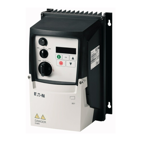
L1 /L L2 /N FW D PW R 9 10 11 IP20 degree of protection IP66 degree of protection, without IP66 degree of protection, with local local controls controls Figure 1: Designs, enclosure versions DC1 variable frequency drive 12/13 MN04020003Z-EN www.eaton.com... -
Page 15: System Overview
Integrable DX-BR… braking resistance (only for IP20, FS2 and FS3) d DXC-EXT-… expansion module e DX-NET-SWD3 SmartWire-DT interface (only in IP20) f DX-COM-STICK communication module and accessories (e. g. DX-CBL-… connection cable) g DE-KEY-… keypad (external) DC1 variable frequency drive 12/13 MN04020003Z-EN www.eaton.com... -
Page 16: Checking The Delivery
Open the packaging with adequate tools and inspect the contents immedi- ately after receipt in order to ensure that they are complete and undamaged. DC1 variable frequency drive 12/13 MN04020003Z-EN www.eaton.com... - Page 17 IL04020013Z for devices with an IP66 degree of protection • A data carrier (CD-ROM) containing documentation for the variable frequency drives L1 /L L2 /N 9 10 11 Figure 4: Equipment supplied DC1 variable frequency drive 12/13 MN04020003Z-EN www.eaton.com...
-
Page 18: Rated Operational Data
Read the manual (in this case MN04020003Z-EN) before making any electrical connections and commissioning. IP20/Open type Degree of protection of the housing: IP 20, UL (cUL) Open Type 25072012 Manufacturing date: 25.07.2012 DC1 variable frequency drive 12/13 MN04020003Z-EN www.eaton.com... -
Page 19: Key To Part Numbers
S = Single-phase mains connection / single-phase motor connection Device series DC1 = variable frequency drive, compact, Series 1 (D = Drives, C = Compact, 1 = Series) Figure 5: Key to part numbers 1) Please refer to manual MN04020004Z-EN DC1 variable frequency drive 12/13 MN04020003Z-EN www.eaton.com... - Page 20 IEC/EN 61800-3 in order to comply with the relevant limits concerning electromagnetic compatibility (EMC). → In accordance with IEC/EN 61800-3, an external radio interfer- ence suppression filter is required for DC1-…Nx-… models. DC1 variable frequency drive 12/13 MN04020003Z-EN www.eaton.com...
-
Page 21: Designations For The Elements In Variable Frequency Drives With An Ip20 Degree Of Protection
Cutout for mounting on mounting rail d Connection terminals in power section (motor feeder) e Control signal terminals (plug-in) f Communication interface (RJ45) g Operating unit with 5 control buttons and LED display h Info card DC1 variable frequency drive 12/13 MN04020003Z-EN www.eaton.com... -
Page 22: Designations For The Elements In Variable Frequency Drives With An Ip66 Degree Of Protection
Connection terminals in power section (mains side) and cableway for cable gland i Communication interface (RJ45) The info card and three additional knockouts for cable glands are found under the lower terminal cover. DC1 variable frequency drive 12/13 MN04020003Z-EN www.eaton.com... -
Page 23: Features
Braking chopper for external braking resistance (DC+ and BR connection only in FS2 and FS3 sizes) g Inverter. The IGBT based inverter converts the DC voltage of the DC link (U ) into a three-phase AC voltage (U ) with variable amplitude and frequency (f DC1 variable frequency drive 12/13 MN04020003Z-EN www.eaton.com... - Page 24 DC1-34…: 0.75 - 11 kW (400 V, 50 Hz) or 1 - 15 HP (460 V, 60 Hz) j Control section with operating unit and control buttons, seven-segment display, control voltage, plug-in control signal terminals k RJ45 interface for the computer and fieldbus connection (OP bus, Modbus RTU, CANopen) DC1 variable frequency drive 12/13 MN04020003Z-EN www.eaton.com...
-
Page 25: Selection Criteria
If necessary, for damp- ening and compensating the deviating current values, motor reactors or sine filters must be installed between the variable frequency drive and the motor. DC1 variable frequency drive 12/13 MN04020003Z-EN www.eaton.com... -
Page 26: Proper Use
(bypass). Observe the technical data and connection requirements. For additional information, refer to the equipment rating plate or label of the variable frequency drive and the documentation. Any other usage constitutes improper use. DC1 variable frequency drive 12/13 MN04020003Z-EN www.eaton.com... -
Page 27: Maintenance And Inspection
Relative average air humidity: < 95 %, non condensing (EN 50178), • To prevent damage to the RASP DC link capacitors, storage times longer than 12 months are not recommended (→ Section 1.12, „Charging the internal DC link capacitors“). DC1 variable frequency drive 12/13 MN04020003Z-EN www.eaton.com... -
Page 28: Charging The Internal Dc Link Capacitors
If some of the information printed on the rating plate is not legible, please state only the data which are clearly legible. Information concerning the guarantee can be found in the Terms and Conditions Eaton Industries GmbH. 24-hour hotline: +49 (0)1805 223 822 E-Mail: AfterSalesEGBonn@eaton.com DC1 variable frequency drive 12/13 MN04020003Z-EN www.eaton.com... - Page 29 (→ Table 37, page 221). The effective direction of a coupled machine will allow the motor to start. All emergency switching off functions and safety functions are in an appropriate condition. DC1 variable frequency drive 12/13 MN04020003Z-EN www.eaton.com...
- Page 30 DANGER Following a shutdown (fault, mains voltage off), the motor can start automatically (when the supply voltage is switched back on) if the automatic restart function has been enabled (→ parameters P-31). DC1 variable frequency drive 12/13 MN04020003Z-EN www.eaton.com...
- Page 31 You can skip this section if you want to set up the parameters directly for optimal operation of the variable frequency drive based on the motor data (rating plate) and the application. Following are a series of simplified connecting examples that use the default configuration: DC1 variable frequency drive 12/13 MN04020003Z-EN www.eaton.com...
- Page 32 Terminal 1: FWD = Clockwise rotating field (Forward Run) • Terminal 2: REV = Counterclockwise rotating field (Reverse Run) The FWD and REV control commands are interlocked (exclusive OR) and require a rising voltage edge. DC1 variable frequency drive 12/13 MN04020003Z-EN www.eaton.com...
- Page 33 Information on settings and the description of the parameters used here is provided in section “Drives control”, Page 105. +24 V STOP P-07 = 50 Hz ① P-03 = 5 s Figure 57: Start-Stop command with maximum setpoint value voltage, acceleration ramp 5 s DC1 variable frequency drive 12/13 MN04020003Z-EN www.eaton.com...
- Page 34 Setpoint value voltage +10 V (Output, maximum 10 mA) Frequency reference value f-Set (Input 0 – +10 V) ① Reference potential (0 V) ① Make sure that the enable contacts (FWD/REV) are open before switching on the mains voltage. DC1 variable frequency drive 12/13 MN04020003Z-EN www.eaton.com...
- Page 35 ① (0 - +10 V proportional voltage signal). The change in output frequency here is delayed based on the specified acceleration and deceleration ramps. When using the device's default settings, these times will be set to 5 seconds. DC1 variable frequency drive 12/13 MN04020003Z-EN www.eaton.com...
- Page 36 2 in order to get a start enable. Press the Stop pushbutton in order to get to the setpoint input display automatically. Use the ▲ and ▼ arrow keys to change the setpoint value. DC1 variable frequency drive 12/13 MN04020003Z-EN www.eaton.com...
- Page 37 When the REV operating direction is in effect, the frequency will have a minus sign. Minus sign for REV operating direction When the Stop pushbutton is pressed, the variable frequency drive will be stopped with the deceleration time configured in P-04. DC1 variable frequency drive 12/13 MN04020003Z-EN www.eaton.com...
- Page 38 → For more information, please refer to chapters 7 and 8. For more information on SmartWire-DT, please refer to manual MN04012009Z, "DX-NET-SWD. SmartWire-DT Interface Card for DC1 Variable Frequency Drives." DC1 variable frequency drive 12/13 MN04020003Z-EN www.eaton.com...
-
Page 39: Parameters
• Increase output frequency / motor speed if P-12 = 1 or P-12 = 2 • Decrement numeric value or parameter number • Reduce output frequency / motor speed if P-12 = 1 or P-12 = 2 DC1 variable frequency drive 12/13 MN04020003Z-EN www.eaton.com... -
Page 40: Shortcuts
When the specified supply voltage (L1/L, L2/N, L3 connection terminals) is applied, the DC1 variable frequency drive will automatically perform a self- test: The LED display will light up and, depending on the selected operating mode, will display Stop or the appropriate value. DC1 variable frequency drive 12/13 MN04020003Z-EN www.eaton.com... -
Page 41: Setting Parameters
5.2.3 Field bus/SmartWire DT A DC1 variable frequency drive's parameters can be configured via a field bus orSmartWire-DT. → For more information, please refer to chapters 7 and 8 and to manual MN04012009Z-EN. DC1 variable frequency drive 12/13 MN04020003Z-EN www.eaton.com... -
Page 42: List Of Parameters
P-14 will be shown. To access the extended parameter set, enter 101 (= WE and P-37) for parameter P-14. P-01 P-01 P-02 P-02 P-03 P-03 P-14 P-14 P-15 P-16 P-53 Figure 60: Parameter Access DC1 variable frequency drive 12/13 MN04020003Z-EN www.eaton.com... -
Page 43: Parameter Lock
"P-dEf" is shown on the display. → The fault log (P-13) and the monitor log will not be restored to their default settings when the parameters are reset! DC1 variable frequency drive 12/13 MN04020003Z-EN www.eaton.com... -
Page 44: I/0 Control
FWD switch position will drive DI1 and the REV switch position will drive DI2. → The FWD and REV designations refer to the default settings. The above functions may change if changes are made to the P-15 parameter. DC1 variable frequency drive 12/13 MN04020003Z-EN www.eaton.com... -
Page 45: Digital And Analog Inputs
DI3 can become AI2; AI1 can become DI4. The following tables show how parameter P-15 depends on parameter P-12. → For the button commands, please note that stop commands are run as N/C contact commands. DC1 variable frequency drive 12/13 MN04020003Z-EN www.eaton.com... - Page 46 Negative fixed frequencies are inverted it Run REV is selected. 1) FWD switch position only for IP66 degree of protection with local controls 2) REV switch position only for IP66 degree of protection with local controls 3) Button command DC1 variable frequency drive 12/13 MN04020003Z-EN www.eaton.com...
- Page 47 DI3. 1 = Enable 1) FWD switch position only for IP66 degree of protection with local controls 2) REV switch position only for IP66 degree of protection with local controls 3) Button command DC1 variable frequency drive 12/13 MN04020003Z-EN www.eaton.com...
- Page 48 Negative fixed frequencies are inverted it Run REV is selected. 1) FWD switch position only for IP66 degree of protection with local controls 2) REV switch position only for IP66 degree of protection with local controls 3) Button command DC1 variable frequency drive 12/13 MN04020003Z-EN www.eaton.com...
-
Page 49: Operational Data Indicator
(undervoltage does not count as a trip) – Not reset when mains power is switched off/on unless a trip occurred before the mains power was switched off. DC1 variable frequency drive 12/13 MN04020003Z-EN www.eaton.com... - Page 50 Control signal terminal 2 actuated (DI1) 0100 Control signal terminal 3 actuated (DI2) 0010 Control signal terminal 4 actuated (DI3) 0001 Control signal terminal 6 actuated (DI4) 0101 Control signal terminals 3 and 6 actuated (DI2 + DI4) DC1 variable frequency drive 12/13 MN04020003Z-EN www.eaton.com...
- Page 51 7-segment digital display assembly. → The values in the fault log (P-13) will not be deleted if the variable frequency drive is reset to its default settings! DC1 variable frequency drive 12/13 MN04020003Z-EN www.eaton.com...
- Page 52 The two dots on the right will flash. The oldest error message will be shown after you press the ▲ arrow key (Up) once more. Example: V-Volt (undervoltage message) The three dots on the right will flash. DC1 variable frequency drive 12/13 MN04020003Z-EN www.eaton.com...
- Page 53 • Mains undervoltage occurs during operation, check the power supply voltage. Overtemperature Heat sink overtemperature • Check the variable frequency drive's ambient air temperature. Check whether additional clear- ance or cooling is required. DC1 variable frequency drive 12/13 MN04020003Z-EN www.eaton.com...
- Page 54 • The motor pick-up control function did not deter- SPIn-F fault catching spinning motors) failed mine the motor speed. Thermistor fault Defective thermistor on heat sink • Please contact your closest Eaton representa- th-Frt tive. Data error Internal memory error • Parameter not stored; restore default settings. dAtA-F •...
- Page 55 0 - 30000 rpm Nominal speed of the motor 38, 110; (min AP040022, AP040014 P-11 ✓ 0.00 - 20.0 % Voltage amplification 114; AP040036 1) Depends on the variable frequency drive's rated power DC1 variable frequency drive 12/13 MN04020003Z-EN www.eaton.com...
- Page 56 5 = t20-4 20 - 4 mA signal 6 = r20-4 20 - 4 mA signal P-17 ✓ 8, 12, 16, 24, 32 Pulse frequency 1) Depends on the variable frequency drive's rated power DC1 variable frequency drive 12/13 MN04020003Z-EN www.eaton.com...
- Page 57 0.00 - 50.00 Hz Frequency skip 1, center 126; AP040026 P-28 – 0.00 - P-07 V V/Hz characteristic curve modification voltage 114; AP040036 P-29 – 0.00 - P-09 Hz V/Hz characteristic curve modification frequency 114; AP040036 DC1 variable frequency drive 12/13 MN04020003Z-EN www.eaton.com...
- Page 58 138, 153 1 - 63 Variable frequency drive slave address Modbus RTU baud rate 9.6 kBit/s 19.2 Kbit/s 38.4 kBit/s 57.6 kBit/s 115.2 kBit/s TimedOut 3000 138, 154 t 30 ms t 100 ms DC1 variable frequency drive 12/13 MN04020003Z-EN www.eaton.com...
- Page 59 5 = r 20-4 20 - 4 mA (≦ 3 mA → delay time 1) P-48 ✓ 0.1 - 25.0 s Standby-time Deactivated P-49 ✓ 0.0 - 100.0 % PI controller, feedback wakeup level DC1 variable frequency drive 12/13 MN04020003Z-EN www.eaton.com...
- Page 60 → Manual MN04012009Z No response: device keeps running Sets warning bit, Device keeps running Sets error bit: stop with ramp Sets error bit: stop with second ramp Sets error bit: switches power off DC1 variable frequency drive 12/13 MN04020003Z-EN www.eaton.com...
- Page 61 P00-18 – Control section firmware version Power section firmware version P00-19 – Serial number of variable frequency drive P00-20 – Variable frequency drive part no. Rated power of variable frequency drive Firmware Version DC1 variable frequency drive 12/13 MN04020003Z-EN www.eaton.com...
- Page 62 ....59 ......197 DC1 variable frequency drive 12/13 MN04020003Z-EN www.eaton.com...
- Page 63 Menu navigation (operating unit) ... . 94 MMX-COM-PC PC interface card ... 194 DC1 variable frequency drive 12/13 MN04020003Z-EN www.eaton.com...
- Page 64 ......9 PES (protective earth shielding) ....9 DC1 variable frequency drive 12/13 MN04020003Z-EN www.eaton.com...
- Page 65 ....... . . 25 DC1 variable frequency drive 12/13 MN04020003Z-EN www.eaton.com...
Need help?
Do you have a question about the PowerXL DC1 and is the answer not in the manual?
Questions and answers