Eaton PowerXL DC1 Installation Manual
Variable frequency drives
Hide thumbs
Also See for PowerXL DC1:
- Manual (238 pages) ,
- Setup & troubleshooting (12 pages) ,
- Communications manual (85 pages)

Related Manuals for Eaton PowerXL DC1


Summary of Contents for Eaton PowerXL DC1
- Page 1 Manual 04/16 MN04020003Z-EN PowerXL ™ Variable Frequency Drives Installation Manual...
- Page 2 1. edition 2012, publication date 10/12 2. edition 2013, publication date 12/13 3. edition 2016, publication date 04/16 © 2012 by Eaton Industries GmbH, 53105 Bonn Authors: Sven Stahlmann, Jörg Randermann, Philipp Hergarten Redaction: René Wiegand All rights reserved, also for the translation.
- Page 3 Danger! Dangerous electrical voltage! Before commencing the installation • Disconnect the power supply of the device. • Wherever faults in the automation system may cause damage to persons or property, external measures must • Ensure that devices cannot be accidentally retriggered. be implemented to ensure a safe operating state in the •...
-
Page 5: Table Of Contents
Electrical power network ............. 37 2.2.1 Mains terminal and configuration..........37 2.2.2 Mains voltage and frequency ............38 2.2.3 Voltage balance ................38 2.2.4 Total Harmonic Distortion (THD) ..........39 2.2.5 Reactive power compensation devices ........39 DC1 Variable Frequency Drive 04/16 MN04020003Z-EN www.eaton.com... - Page 6 3.5.5 EMC cable brackets ..............72 3.5.6 General installation diagram............74 Electrical Installation ..............75 3.6.1 Connection to power section............76 3.6.2 Connection on control section ............. 86 3.6.3 Thermistor connection ..............95 DC1 Variable Frequency Drive 04/16 MN04020003Z-EN www.eaton.com...
- Page 7 DC1-34…device series..............138 Dimensions .................. 140 6.3.1 Frame sizes FS1 to FS3 in IP20 ........... 140 6.3.2 Frame size FS4 in IP20..............141 6.3.3 Frame sizes FS1 to FS3 in IP66 ........... 142 DC1 Variable Frequency Drive 04/16 MN04020003Z-EN www.eaton.com...
- Page 8 Device-specific accessories ............163 7.1.1 DXC-EXT-IO… coupling module........... 164 7.1.2 DXC-EXT-2RO output expansion..........166 7.1.3 DXC-EXT-2RO1AO output expansion .......... 168 7.1.4 DXC-EXT-LOCSIM simulator............170 General accessories (List) ............171 Alphabetical index ..............173 DC1 Variable Frequency Drive 04/16 MN04020003Z-EN www.eaton.com...
-
Page 9: About This Manual
A separate manual – MN04020004Z-EN (“Parameter Manual”) – goes over how to configure the parameters for DC1 variable frequency drives and provides application examples as well. This manual is available on the Eaton website at: http://www.eaton.de/EN/EatonDE/ProdukteundLoesungen/Electrical/ Kundensupport/DownloadCenter/index.htm → Customer support → Download Center –... -
Page 10: Writing Conventions
→ All the specifications in this manual refer to the hardware and software versions documented in it. DC1 Variable Frequency Drive 04/16 MN04020003Z-EN www.eaton.com... -
Page 11: Documents With Additional Information
0.3 Documents with additional information → More information on the devices described here can be found on the Internet under: www.eaton.eu/powerxl as well as in EATON Download Center: http://www.eaton.de/EN/EatonDE/ProdukteundLoesungen/Electrical/ Kundensupport/DownloadCenter/index.htm In the Quick Search box, enter the document name (“MN04020003”, for example). -
Page 12: Mains Supply Voltages
-17.222 °C (T × 9/5 + 32 Speed Revolutions per minute 1 rpm 1 min Weight pound 1 lb 0.4536 kg 2.205 Flow rate cubic feed per minute 1 cfm 1.698 m /min 0.5889 DC1 Variable Frequency Drive 04/16 MN04020003Z-EN www.eaton.com... -
Page 13: Dc1 Device Series
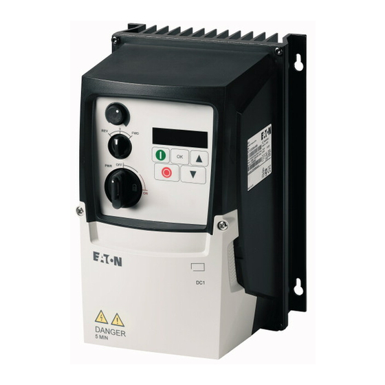
FW D PW R L1/L L2/N 9 10 11 DC+ BR IP20 degree of IP66 degree of protection IP66 degree of protection, with local protection controls Figure 1: Designs and enclosure versions DC1 Variable Frequency Drive 04/16 MN04020003Z-EN www.eaton.com... -
Page 14: System Overview
DX-LN… mains choke, DX-LM3-… motor choke, DX-SIN3-… sine filter d DX-BR… braking resistance e DXC-EXT-… expansion module f DX-NET-SWD3 SmartWire-DT interface g DX-COM-STICK communication module and accessories (e. g. DX-CBL-… connection cable) h DE-KEY-… keypad (external) DC1 Variable Frequency Drive 04/16 MN04020003Z-EN www.eaton.com... -
Page 15: Checking The Delivery
IL04020013Z for devices with an IP66 degree of protection L1 /L L2 /N 9 10 11 Figure 3: Equipment supplied (example: devices with IP20 / IP66 degree of protection with instruction leaflet) DC1 Variable Frequency Drive 04/16 MN04020003Z-EN www.eaton.com... -
Page 16: Rated Operational Data
Figure 4: Nameplate location ) is a simplified version that can be The nameplate on top (nameplate used to clearly identify the device if the main nameplate (nameplate is blocked by other devices. DC1 Variable Frequency Drive 04/16 MN04020003Z-EN www.eaton.com... - Page 17 Manufacturing date: 07-25-2012 Max amb. 50 °C Maximum permissible ambient air temperature (50 °C) variable frequency drive is an electrical apparatus. Read the manual (in this case MN04020003Z-EN) before making any electrical connections and commissioning. DC1 Variable Frequency Drive 04/16 MN04020003Z-EN www.eaton.com...
-
Page 18: Key To Part Numbers
S = Single-phase mains connection / single-phase motor Device series DC1 = variable frequency drive, compact, Series 1 (D = Drives, C = Compact, 1 = Series) Figure 5: Key to part numbers 1) Please refer to manual MN04020004Z-EN DC1 Variable Frequency Drive 04/16 MN04020003Z-EN www.eaton.com... - Page 19 6S = Degree of protection IP66 / NEMA 4X with switches (mains switch, enable/phase sequence, potentiometer) for local control N = basic device 1) See following note → In accordance with IEC/EN 61800-3, an external radio interference suppression filter is required for DC1-…Nx-… models. DC1 Variable Frequency Drive 04/16 MN04020003Z-EN www.eaton.com...
-
Page 20: Features
✓ DC1-1D5D8NN-A20N 1-1/2 – – IP20 ✓ DC1-1D5D8NN-A66N 1-1/2 – – IP66 ✓ ✓ DC1-1D5D8NN-A6SN 1-1/2 – IP66 1) As per IEC standards 2) As per UL 61800-5-1, Table DVE.1, March 6, 2015 DC1 Variable Frequency Drive 04/16 MN04020003Z-EN www.eaton.com... - Page 21 ✓ DC1-127D0NB-A6SN – IP66 ✓ ✓ ✓ DC1-127D0FB-A6SN IP66 ✓ DC1-12011NB-A20N 10.5 – – IP20 ✓ ✓ DC1-12011FB-A20N 10.5 – IP20 ✓ DC1-12011NB-A66N 10.5 – – IP66_x ✓ ✓ DC1-12011FB-A66N 10.5 – IP66_x DC1 Variable Frequency Drive 04/16 MN04020003Z-EN www.eaton.com...
- Page 22 5) Rated operational current at switching frequencies of up to 8 kHz and ambient temperatures of up to +40 °C 6) For UL conformity: Rated operational current at ambient temperatures of up to +45 °C over a period of 24 hours DC1 Variable Frequency Drive 04/16 MN04020003Z-EN www.eaton.com...
- Page 23 DC1-32011FB-A6SN 10.5 IP66 ✓ DC1-32018NB-A20N – – IP20 ✓ ✓ DC1-32018FB-A20N – IP20 ✓ DC1-32018NB-A66N – – IP66 ✓ ✓ DC1-32018FB-A66N – IP66 ✓ ✓ DC1-32018NB-A6SN – IP66 ✓ ✓ ✓ DC1-32018FB-A6SN IP66 DC1 Variable Frequency Drive 04/16 MN04020003Z-EN www.eaton.com...
- Page 24 5) Rated operational current at switching frequencies of up to 8 kHz and ambient temperatures of up to +40 °C 6) For UL conformity: Rated operational current at ambient temperatures of up to +45 °C over a period of 24 hours DC1 Variable Frequency Drive 04/16 MN04020003Z-EN www.eaton.com...
- Page 25 DC1-345D8FB-A20N – IP20 ✓ DC1-345D8NB-A66N – – IP66 ✓ ✓ DC1-345D8FB-A66N – IP66 ✓ ✓ DC1-345D8NB-A6SN – IP66 ✓ ✓ ✓ DC1-345D8FB-A6SN IP66 ✓ DC1-349D5NB-A20N – – IP20 ✓ ✓ DC1-349D5FB-A20N – IP20 DC1 Variable Frequency Drive 04/16 MN04020003Z-EN www.eaton.com...
- Page 26 4) Rated operational current at switching frequencies of up to 8 kHz and ambient temperatures of up to +50 °C 5) Rated operational current at switching frequencies of up to 8 kHz and ambient temperatures of up to +40 °C DC1 Variable Frequency Drive 04/16 MN04020003Z-EN www.eaton.com...
-
Page 27: Description
Cutout for mounting on mounting rail d Connection terminals in power section (motor feeder) e Control terminals (plug-in) f Communication interface (RJ45) g Keypad with 5 control buttons and LED display h Info card DC1 Variable Frequency Drive 04/16 MN04020003Z-EN www.eaton.com... -
Page 28: Ip66 Degree Of Protection (Fs1 To Fs3)
Cover for connection terminals, featuring info cards The info cards are found on the inside of the lower cover ⑩, which features three additional knockouts for cable glands leading to the control section. DC1 Variable Frequency Drive 04/16 MN04020003Z-EN www.eaton.com... -
Page 29: Voltage Categories
Motor: 0.37 - 4 kW (230 V, 50 Hz), 1/2 - 5 HP (230 V, 60 Hz) Motor FS1, FS2, FS3 L1/L L2/N 230 V (U = 1 ~ 230 V) 3 ∼ EMC Filter Brake Chopper (FS2, FS3) Figure 9: DC1-12… DC1 Variable Frequency Drive 04/16 MN04020003Z-EN www.eaton.com... - Page 30 FS1, FS2, FS3, FS4 L1/L 400 V (U = 3 ~ 400 V) L2/N 460 V (U = 3 ~ 480 V) 3 ∼ EMC Filter Brake Chopper (FS2, FS3, FS4) Figure 11: DC1-34… DC1 Variable Frequency Drive 04/16 MN04020003Z-EN www.eaton.com...
-
Page 31: Selection Criteria
DC1-34…: 3-phase main terminal, rated operating voltage: 400 V • DC1-…2D2…: 2.2 A – The variable frequency drive’s rated operational current (output current) guarantees that the motor will be supplied with the required rated operational current (1.9 A). DC1 Variable Frequency Drive 04/16 MN04020003Z-EN www.eaton.com... - Page 32 It may be necessary to install motor chokes or sine filters between the variable frequency drive and the motor in order to dampen and compensate for deviating current values. DC1 Variable Frequency Drive 04/16 MN04020003Z-EN www.eaton.com...
-
Page 33: Output Reduction (Derating)
(double modulation). For more information on the subject of derating, please refer to Application Note AP040038EN, “DC1 Variable Frequency Drives – Dependency of the output current on switching frequency and ambient temperature”. ftp://ftp.moeller.net/DRIVES/POWERXL/01_APPLICATION_NOTE/ Deutsch/DC1/AP040038DE_DC1_Derating.pdf DC1 Variable Frequency Drive 04/16 MN04020003Z-EN www.eaton.com... - Page 34 14 A - 35 % - 10 % - 12.5 % = (14 x 0.65 x 0.9 x 0.875) A = approx. 7.2 A The DC1-34014FB-A6SN variable frequency drive meets the necessary operating conditions. DC1 Variable Frequency Drive 04/16 MN04020003Z-EN www.eaton.com...
-
Page 35: Proper Use
Always observe the technical data and connection conditions! For additional information, refer to the equipment nameplate or label at the variable frequency drive and the documentation. Any other use will be considered to be an improper use of the device. DC1 Variable Frequency Drive 04/16 MN04020003Z-EN www.eaton.com... -
Page 36: Maintenance And Inspection
To prevent damage to the variable speed starter’s internal DC link capacitors, it is not recommended to store the variable frequency drive for more than 12 months (→ Section 1.12, “Charging the internal DC link capacitors“). DC1 Variable Frequency Drive 04/16 MN04020003Z-EN www.eaton.com... -
Page 37: Charging The Internal Dc Link Capacitors
Information concerning the guarantee can be found in the Terms and Conditions Eaton Industries GmbH. Break-Down Service Please contact your local office: http://www.eaton.eu/aftersales Hotline After Sales Service +49 (0) 180 5 223822 (de, en) AfterSalesEGBonn@eaton.com DC1 Variable Frequency Drive 04/16 MN04020003Z-EN www.eaton.com... - Page 38 1 DC1 device series 1.13 Service and warranty DC1 Variable Frequency Drive 04/16 MN04020003Z-EN www.eaton.com...
-
Page 39: Engineering
All applicable laws and local standards must be complied with when planning and carrying out the installation. Not following the recommendations provided may result in problems what will not be covered by the warranty. DC1 Variable Frequency Drive 04/16 MN04020003Z-EN www.eaton.com... - Page 40 (Temperature, motor speed) g Load system: Driven system equipment (process, speed, torque) ⑥ ϑ ⑦ M, n Figure 13: Magnet system example (overall system as its own system or as part of a larger system) DC1 Variable Frequency Drive 04/16 MN04020003Z-EN www.eaton.com...
-
Page 41: Electrical Power Network
EMC- and Low Voltage Directive. Good earthing measures are a prerequisite for the effective Use of further measures such as screen earth kit or filters here. Without respective grounding measures, further steps are superfluous. DC1 Variable Frequency Drive 04/16 MN04020003Z-EN www.eaton.com... -
Page 42: Mains Voltage And Frequency
→ For the rated mains contactors for DC1 variable frequency drives, please refer to → Section 2.5, “Mains chokes“, page 42. DC1 Variable Frequency Drive 04/16 MN04020003Z-EN www.eaton.com... -
Page 43: Total Harmonic Distortion (Thd)
→ Section 6.2, “Specific rated operational data“, page 133 provides the leakage currents for the individual models. → → Section 3.5, “EMC installation“, page 66 goes over the EMC requirements for the motor cables. DC1 Variable Frequency Drive 04/16 MN04020003Z-EN www.eaton.com... -
Page 44: Safety And Switching
The fuses will protect the supply cable in the event of a short-circuit, limit any damage to the variable frequency drive, and prevent damage to upstream devices in the event of a short-circuit in the variable frequency drive. DC1 Variable Frequency Drive 04/16 MN04020003Z-EN www.eaton.com... -
Page 45: Residual Current Circuit-Breaker (Rcd)
1.25 times higher input current. → For the rated mains contactors for DC1 variable frequency drives, please refer to → Section 6.6, “Mains contactors“, page 148. DC1 Variable Frequency Drive 04/16 MN04020003Z-EN www.eaton.com... -
Page 46: Mains Chokes
96 % of the mains voltage U → For the rated mains contactors for DC1 variable frequency drives, please refer to → Section 2.5, “Mains chokes“, page 42. DC1 Variable Frequency Drive 04/16 MN04020003Z-EN www.eaton.com... -
Page 47: Radio Interference Suppression Filter
In the case of power drive systems (PDS) with variable frequency drives, electromagnetic compatibility (EMC) measures must already be taken into account during the engineering stage, as making changes during assembly and installation and retroactively fixing things will be more expensive. DC1 Variable Frequency Drive 04/16 MN04020003Z-EN www.eaton.com... -
Page 48: Braking Resistances
DC link voltage of approximately 780 V DC and then back off at 756 V DC. During this stage, the braking transistor and the brake resistor will be active continuously. DC1 Variable Frequency Drive 04/16 MN04020003Z-EN www.eaton.com... - Page 49 • (at least 30 %), e.g., for elevators, downhill conveyors, winders, centrifuges, flywheel motors, and large fans. Motor Mains PEAK Brems Brems Figure 16: Braking cycle, fast motor stop with external brake resistor DC1 Variable Frequency Drive 04/16 MN04020003Z-EN www.eaton.com...
- Page 50 Use brake resistors with the recommended R resistance Brec values for the DC1 variable frequency drives’ ratings. → For the rated braking resistances for DC1 variable frequency drives, please refer to → Section 2.7, “Braking resistances“, page 44. DC1 Variable Frequency Drive 04/16 MN04020003Z-EN www.eaton.com...
-
Page 51: Motor Chokes
For the rated motor chokes for DC1 variable frequency drives, please refer to → Section 2.8, “Motor chokes“, page 47. For more information and technical data on DX-LM3… motor chokes, please refer to instruction leaflet IL00906003Z. DC1 Variable Frequency Drive 04/16 MN04020003Z-EN www.eaton.com... -
Page 52: Sine Filter
) to a value as low as 2 kHz (= P-17 setting, 4 kHz, double modulation) → Only sine filters that allow this minimum switching frequency of 2 kHz during operation should be used with DC1 variable frequency drives. DC1 Variable Frequency Drive 04/16 MN04020003Z-EN www.eaton.com... -
Page 53: Switching To The Output Side
(as with DOL starting). → Vacuum contactors are not suitable for switching at low frequencies and should not be used at the output of DC1 variable frequency drives. DC1 Variable Frequency Drive 04/16 MN04020003Z-EN www.eaton.com... -
Page 54: Switch-Disconnectors
EN 60204. Eaton T0…/MSB/…, P1…/MSB/…, and P3…/MSB/… enclosed switch- disconnectors are designed for local installation with an IP65 degree of protection. The internal screening plate ensures that screened motor cables can be easily connected in a way that meets EMC requirements. -
Page 55: Bypass Circuit
When the motor is being switched off, the output (U, V, W) of variable frequency drive T1 must be disabled (the FWD/REV enable signal must be switched off) before the contacts at S1 are opened. DC1 Variable Frequency Drive 04/16 MN04020003Z-EN www.eaton.com... -
Page 56: Connecting Motors In Parallel
In applications with motors that will be connected and disconnected, we recommend using a motor choke or a sine filter. DC1 Variable Frequency Drive 04/16 MN04020003Z-EN www.eaton.com... - Page 57 F1, F2, F3, …: Overload relay (bimetallic relay or PKE) U1 V1 W1 U1 V1 W1 U1 V1 W1 ˜ ˜ ˜ Figure 19: Example: Parallel connection of several motors to one variable frequency drive DC1 Variable Frequency Drive 04/16 MN04020003Z-EN www.eaton.com...
-
Page 58: Three-Phase Motor
(in order to ensure that the motor will be protected). • When running tests or commissioning a system with significantly lower motor outputs, the motor’s rated operational current must be adjusted using parameter P-08 ("rated motor current"). DC1 Variable Frequency Drive 04/16 MN04020003Z-EN www.eaton.com... -
Page 59: Circuit Types With Three-Phase Motors
230 V; output voltage: three-phase 230 V → DC1-124D3… Motor connection DC1 variable according to according to frequency drive U1 (-U2) T1 (-T4) V1 (-V2) T2 (-T5) W1 (-W2) T3 (-T6) DC1 Variable Frequency Drive 04/16 MN04020003Z-EN www.eaton.com... -
Page 60: Single-Phase Ac Motors
Temperature sensors in the motor windings (thermistor, Thermo-Click) must not be connected directly to the variable frequency drive, but instead must be connected through a relay approved for the hazardous location (e.g. EMT6). DC1 Variable Frequency Drive 04/16 MN04020003Z-EN www.eaton.com... -
Page 61: Installation
Environments with mechanical vibration and impact loads that go beyond the requirements in EN 50178. • Areas in which the variable frequency drive takes care of safety functions that must guarantee machine and personnel protection. DC1 Variable Frequency Drive 04/16 MN04020003Z-EN www.eaton.com... -
Page 62: Mounting
(e.g., on a metal plate). Figure 22: Surface mounting on metal plate IP66 DC1 variable frequency drives must be installed as required by the local conditions for this degree of protection. DC1 Variable Frequency Drive 04/16 MN04020003Z-EN www.eaton.com... -
Page 63: Mounting Position
1 2 3 4 5 6 7 8 9 10 11 Figure 24: Clearances for air cooling (left: IP20; right: IP66) → The variable frequency drives can be mounted side by side without any lateral clearance between them. DC1 Variable Frequency Drive 04/16 MN04020003Z-EN www.eaton.com... - Page 64 1) ft 3 /min = CFM (cubic foot per minute) 2) For UL conformity, the maximum permissible ambient air temperature over a period of 24 hours is limited to +45 °C for the DC1-127D0…, DC1-32011…, and DC1-32018… variable frequency drives. DC1 Variable Frequency Drive 04/16 MN04020003Z-EN www.eaton.com...
- Page 65 FS1, …, FS4 with DX-NET- 50 mm ( 1.97 inch) SWD3 and SWD4-8SF2-5 Figure 26: Minimum required clearance in front of the ① variable frequency drive when installed in an enclosure (control panel) DC1 Variable Frequency Drive 04/16 MN04020003Z-EN www.eaton.com...
-
Page 66: Fixing
NEMA 0 3.94 10.04 8.85 IP66_x NEMA 4X 7.78 1.2 - 1.5 10.62 - 13.27 IP20 NEMA 0 4.92 15.75 35.4 1 in = 1’’ = 25.4 mm; 1 mm = 0.0394 in DC1 Variable Frequency Drive 04/16 MN04020003Z-EN www.eaton.com... - Page 67 ▶ To do this, place the variable frequency drive on the mounting rail from above [1] and press it down until it snaps into place [2]. Figure 29: Fixing on a mounting rail DC1 Variable Frequency Drive 04/16 MN04020003Z-EN www.eaton.com...
- Page 68 A flat-bladed screwdriver (blade width 5 mm) is recommended for pushing down the clip. f 5 mm (f 0.197“) Figure 30: Dismantling from mounting rails DC1 Variable Frequency Drive 04/16 MN04020003Z-EN www.eaton.com...
-
Page 69: Ip66 / Nema4X Degree Of Protection
Figure 33: DC1-…-A6SN with padlock ▶ Push on the center of the switch in order to open the opening for ⌀ the padlock. ⌀ = 5 mm → 2 x (⌀ = 0.20" → 2 x) DC1 Variable Frequency Drive 04/16 MN04020003Z-EN www.eaton.com... -
Page 70: Emc Installation
→ Do not make connections to painted surfaces (electrolytic oxidation, yellow chromated). → Install the variable frequency drive as directly as possible (without spacers) on a metal plate (mounting plate). DC1 Variable Frequency Drive 04/16 MN04020003Z-EN www.eaton.com... - Page 71 Analog signal cables (measured values, setpoints, and correction values) must be routed inside screened conduit. Figure 35: Separate routing a Power cable: mains voltage, motor connection b Control and signal lines, fieldbus connections DC1 Variable Frequency Drive 04/16 MN04020003Z-EN www.eaton.com...
-
Page 72: Earthing
(e.g., beam, ceiling joist), a ground rod in the ground, or a mains earth bus must meet the requirements set forth in the applicable national and regional industrial safety regulations and/or regulations for electrical systems. DC1 Variable Frequency Drive 04/16 MN04020003Z-EN www.eaton.com... -
Page 73: Internal Filters (Emc And Var Screws)
≧ 40 mm (≧ 1.57") ⏚ EM C L2 L3 9 10 11 ⏚ EM C D C+ B R D C- Figure 37: Two EMC screws on devices with a frame size of FS4 DC1 Variable Frequency Drive 04/16 MN04020003Z-EN www.eaton.com... - Page 74 VAR screw. The screw must be screwed back in after the high potential tests are DC1 Variable Frequency Drive 04/16 MN04020003Z-EN www.eaton.com...
-
Page 75: Screen Earth Kit
(depending on the EMC environment). → Control and signal lines (analog, digital) should always be grounded on one end, in the immediate vicinity of the supply voltage source (PES). DC1 Variable Frequency Drive 04/16 MN04020003Z-EN www.eaton.com... -
Page 76: Emc Cable Brackets
Control cables, motor connection, external braking resistance DX-EMC-MNT-3N Mains connection DX-EMC-MNT-3M Control cables, motor connection, external braking resistance → We recommend connecting the DX-EMC-MNT-… cable brackets to the variable frequency drive before installing it. DC1 Variable Frequency Drive 04/16 MN04020003Z-EN www.eaton.com... - Page 77 Connection example DX-EMC-MNT ... N FS1, FS2: = 4 x M4 FS3: = 4 x M5 1.3 Nm (11.5 lb-in) DX-EMC-MNT ... M Figure 39: EMC cable brackets (example: FS2 frame size) DC1 Variable Frequency Drive 04/16 MN04020003Z-EN www.eaton.com...
-
Page 78: General Installation Diagram
Cable routing: Do not route power cables and control cables parallel to each other in a single cable duct. If they need to be routed in parallel, they should be in separate metal cable ducts (in order to meet EMC requirements). DC1 Variable Frequency Drive 04/16 MN04020003Z-EN www.eaton.com... -
Page 79: Electrical Installation
(5) minutes after the supply voltage has been switched off (intermediate circuit capacitor discharging time). Pay attention to hazard warnings! → Complete the following steps with the specified tools and without using force. DC1 Variable Frequency Drive 04/16 MN04020003Z-EN www.eaton.com... -
Page 80: Connection To Power Section
The number and the arrangement of the connection terminals used depend on the variable frequency drive’s size and model. NOTICE The variable frequency drive must always be connected with ground potential via a grounding conductor (PE). DC1 Variable Frequency Drive 04/16 MN04020003Z-EN www.eaton.com... - Page 81 DC+: Positive DC link connection if using an external DC power supply, DC link coupling, or braking chopper. The terminal’s plastic cover can be removed if necessary. BR: Terminal for brake resistor (braking chopper output). The terminal’s plastic cover can be removed if necessary. DC1 Variable Frequency Drive 04/16 MN04020003Z-EN www.eaton.com...
- Page 82 The terminals’ plastic cover can be removed if necessary. DC+ , BR: Connection for external brake resistors (BR = braking chopper output) The terminals’ plastic cover can be removed if necessary. DC1 Variable Frequency Drive 04/16 MN04020003Z-EN www.eaton.com...
- Page 83 (90 degrees) so that they are in a vertical position [1]. Once the latches are released, you can lift the cover off [2]. PZ 2 Control ③ Figure 42: Removing the lower housing cover DC1 Variable Frequency Drive 04/16 MN04020003Z-EN www.eaton.com...
- Page 84 + , BR: Connection for external brake resistors (BR = Output Brake Chopper) The terminals’ plastic cover can be removed if necessary. Terminal + has the same function as terminal DC+ in devices with an IP20 degree of protection. DC1 Variable Frequency Drive 04/16 MN04020003Z-EN www.eaton.com...
- Page 85 Maximum terminal Tightening moment size capacity mm 2 lb-in 8.85 0.39 8.85 0.39 8.85 10 - 11 0.39 - 0.43 PE connection: Ring terminal with a diameter of 6.3 mm (0.25") ⌀ DC1 Variable Frequency Drive 04/16 MN04020003Z-EN www.eaton.com...
- Page 86 Screened, four-wire cable is recommended for the motor cables. The green- yellow conductor in these cables must be used to connect the motor’s and variable frequency drive’s PE terminals, minimizing the loads on the cable screen (high equalizing currents). DC1 Variable Frequency Drive 04/16 MN04020003Z-EN www.eaton.com...
- Page 87 In the case of units with a frame size of FS1, FS2, or FS3, the screened motor cable can also be connected using an EMC cable bracket (DX-EMC-MNT…M) → Section 3.5.5, “EMC cable brackets“, page 72. DC1 Variable Frequency Drive 04/16 MN04020003Z-EN www.eaton.com...
- Page 88 Due to EMC reasons, you should use an metallic EMC cable gland in the knockout on the right in order to connect the motor cable screen across a large area and ground it. ② Motor ① Mains Figure 48: Installing the cable glands DC1 Variable Frequency Drive 04/16 MN04020003Z-EN www.eaton.com...
- Page 89 PE terminal. 1 2 3 4 5 6 7 8 9 10 11 ⏚ L1/N L2/N ⏚ Figure 49: Grounding the EMC cable gland Figure 50: Example: diagram of EMC gland assembly DC1 Variable Frequency Drive 04/16 MN04020003Z-EN www.eaton.com...
-
Page 90: Connection On Control Section
When using more than one control voltage, we recommend using separate cables. Example 24 V DC at control signal terminals 1, 2, 3, 4, 6, and 8 and 110 or 230 V AC at control signal terminals 10 and 11. DC1 Variable Frequency Drive 04/16 MN04020003Z-EN www.eaton.com... - Page 91 0 V = connection terminal 7 – Relay 1, N/O Maximum switching load: 250 V AC/6 A or 30 V DC/5 A Relay 1, N/O Maximum switching load: 250 V AC/6 A or 30 V DC/5 A DC1 Variable Frequency Drive 04/16 MN04020003Z-EN www.eaton.com...
- Page 92 The control cables should be screened and twisted for the external connection. The screening is applied on one side in the proximity of the variable frequency drive (PES). Figure 53: Screen termination at one end (PES) close to the variable frequency drive DC1 Variable Frequency Drive 04/16 MN04020003Z-EN www.eaton.com...
- Page 93 It is used as an analog output (AO) in the default configuration that comes with the variable frequency drive when it is delivered. Figure 54: Control signal terminals (D = digital / A = analog) DC1 Variable Frequency Drive 04/16 MN04020003Z-EN www.eaton.com...
- Page 94 (DI1 to DI4) and integrate them directly into control circuits with 110 V / 230 V. Values of 80 to 110/230 V AC will be recognized as a high signal, → Section 7.1.1, “DXC-EXT-IO… coupling module“, page 164. DC1 Variable Frequency Drive 04/16 MN04020003Z-EN www.eaton.com...
- Page 95 4 - 20 mA or 20 - 4 mA with open-circuit monitoring (< 3 mA). → Control terminals 7 and 9 are the common 0 V reference potential for all analog and digital input signals. DC1 Variable Frequency Drive 04/16 MN04020003Z-EN www.eaton.com...
- Page 96 30 V DC, max. 5 A We recommend connecting the loads connected to the relay contact as follows: 250 V ∼ : 6 A 30 V ⎓ : 5 A Varistor RC filter Diode DC1 Variable Frequency Drive 04/16 MN04020003Z-EN www.eaton.com...
- Page 97 DC1, DE11 Variable frequency drives” • MN04012009: “PowerXL™ – DX-NET-SWD Interface card SmartWire-DT for Variable Frequency Drives DC1” → DC1 variable frequency drives do not have an internal bus termination resistor. Use DX-CBL-TERM or EASY-NT-R if necessary. DC1 Variable Frequency Drive 04/16 MN04020003Z-EN www.eaton.com...
- Page 98 When the device is set to its default settings, the setpoint value can be set using the potentiometer. Meanwhile, the REV – 0 – FWD selector switch can be used to set the drive’s operating direction (counterclockwise rotating field mode – STOP – clockwise rotating field mode). DC1 Variable Frequency Drive 04/16 MN04020003Z-EN www.eaton.com...
-
Page 99: Thermistor Connection
The tripping range must fall within a resistance value range of approximately 2.5 - 3 kΩ, while the reset range must fall within a range of 1.9 - 1 kΩ. DC1 Variable Frequency Drive 04/16 MN04020003Z-EN www.eaton.com... -
Page 100: Block Diagrams
3 Installation 3.7 Block diagrams 3.7 Block diagrams The following block diagrams show all the connection terminals on a DC1 variable frequency drive and their functions when in their default settings. DC1 Variable Frequency Drive 04/16 MN04020003Z-EN www.eaton.com... -
Page 101: Dc1-1D
DC1-1D… variable frequency drives do not feature an internal radio interference suppression filter. An external radio interference suppression filter is required for operation as per EN 61800-3, → Section 6.8, “Radio interference suppression filter“, page 153. DC1 Variable Frequency Drive 04/16 MN04020003Z-EN www.eaton.com... -
Page 102: Dc1-12
Brake resistor DX-BR3-100 can be inserted underneath the heat sink into the enclosure and electronically protected against overloads (P-34 = 1). DC1-12xxxN…: without radio interference suppression filter DC1-12xxxF…: with built-in radio interference suppression filter DC1 Variable Frequency Drive 04/16 MN04020003Z-EN www.eaton.com... -
Page 103: Dc1-32
Brake resistor DX-BR3-100 can be inserted underneath the heat sink into the enclosure and electronically protected against overloads (P-34 = 1). DC1-32xxxN…, DC1-34xxxN…: without radio interference suppression filter DC1-32xxxF…, DC1-34xxxF…: with built-in radio interference suppression filter DC1 Variable Frequency Drive 04/16 MN04020003Z-EN www.eaton.com... -
Page 104: Dc1-32
Variable frequency drive with three-phase mains supply voltage and three- phase motor connection The two EMC screws connect the mains-side capacitors in the internal radio interference suppression filter and the Y class capacitors to the earthing (PE). DC1 Variable Frequency Drive 04/16 MN04020003Z-EN www.eaton.com... -
Page 105: Dc1-1D
DC link. When there is a power supply of 1 AC 110 - 115 V, a motor voltage of up to 3 AC 230 V will be output. DC1 Variable Frequency Drive 04/16 MN04020003Z-EN www.eaton.com... - Page 106 (IP66). In this case, the connection to the variable frequency drive will require a screened cable with a screen braid that is terminated at both ends to the protective earth (PES) across a large area. DC1 Variable Frequency Drive 04/16 MN04020003Z-EN www.eaton.com...
-
Page 107: Dc1-1D
DC1-1D variable frequency drives do not have an internal radio interference suppression filter. An external radio interference suppression filter is required for operation as per EN 61800-3, → Section 6.8, “Radio interference suppression filter“, page 153. DC1 Variable Frequency Drive 04/16 MN04020003Z-EN www.eaton.com... -
Page 108: Dc1-12
(FWD = Clockwise rotating field, REV = Counterclockwise rotating field) Mains switch (PWR = Power) Frame sizes FS2 and FS3 with connection for external brake resistors DC1-12xxxN…: without radio interference suppression filter DC1-12xxxF…: with built-in radio interference suppression filter DC1 Variable Frequency Drive 04/16 MN04020003Z-EN www.eaton.com... -
Page 109: Dc1-12
Variable frequency drive with IP66 degree of protection, local controls, single-phase mains supply voltage, and three-phase motor connection Frame sizes FS2 and FS3 with connection for external brake resistors DC1-12xxxN…: without radio interference suppression filter DC1-12xxxF…: with built-in radio interference suppression filter DC1 Variable Frequency Drive 04/16 MN04020003Z-EN www.eaton.com... -
Page 110: Dc1-32
Operating direction (FWD = Clockwise rotating field, REV = Counterclockwise rotating field) Mains switch (PWR = Power) Frame sizes FS2 and FS3 with connection for external brake resistors DC1-12xxxN…: without radio interference suppression filter DC1-12xxxF…: with built-in radio interference suppression filter DC1 Variable Frequency Drive 04/16 MN04020003Z-EN www.eaton.com... -
Page 111: Dc1-32
3 AC 230/400/460 V Figure 70: Block diagram DC1-32…-A66N, DC1-34…-A66N Frame sizes FS2 and FS3 with connection for external brake resistors DC1-32xxxN…: without radio interference suppression filter DC1-32xxxF…: with built-in radio interference suppression filter DC1 Variable Frequency Drive 04/16 MN04020003Z-EN www.eaton.com... -
Page 112: Insulation Testing
1000 V. The insulation resistance must be greater than 1 MΩ. → Consider the notes from the motor manufacturer in testing the insulation resistance. DC1 Variable Frequency Drive 04/16 MN04020003Z-EN www.eaton.com... -
Page 113: Protection Against Electric Shock
41.1 or within 5 seconds – depending on the applicable scenario – as per IEC/HD 60364-41 (DIN VDE 0100-410; VDE 0100-410):2007-06). DC1 Variable Frequency Drive 04/16 MN04020003Z-EN www.eaton.com... - Page 114 3 Installation 3.9 Protection against electric shock DC1 Variable Frequency Drive 04/16 MN04020003Z-EN www.eaton.com...
-
Page 115: Operation
( → MN04020004Z). The effective direction of a coupled machine will allow the motor to start. All emergency switching off functions and safety functions are in an appropriate condition. DC1 Variable Frequency Drive 04/16 MN04020003Z-EN www.eaton.com... -
Page 116: Operational Hazard Warnings
DANGER Following a shutdown (fault, mains voltage off), the motor can start automatically (when the supply voltage is switched back on) if the automatic restart function has been enabled (→ parameters P-31). DC1 Variable Frequency Drive 04/16 MN04020003Z-EN www.eaton.com... - Page 117 If motors are to be operated with frequencies higher than the standard 50 or 60 Hz, then these operating ranges must be approved by the motor manufacturer. The motors could be damaged otherwise. DC1 Variable Frequency Drive 04/16 MN04020003Z-EN www.eaton.com...
-
Page 118: Commissioning With Control Terminals (Default Settings)
The FWD and REV control commands are interlocked (exclusive OR) and require a rising voltage edge. The frequency is shown with a minus sign with a start release with a left rotating field (REV). DC1 Variable Frequency Drive 04/16 MN04020003Z-EN www.eaton.com... - Page 119 This will cause the motor to coast to a stop – see below. +24 V STOP P-07 = 50 Hz ① P-03 = 5 s Figure 71: Start-Stop command with maximum setpoint value voltage, acceleration ramp 5 s DC1 Variable Frequency Drive 04/16 MN04020003Z-EN www.eaton.com...
-
Page 120: Commissioning With Local Controls
. Output frequency changes will be delayed based on the specified acceleration and deceleration times. When using the device’s default settings, these times will be set to 5 seconds. DC1 Variable Frequency Drive 04/16 MN04020003Z-EN www.eaton.com... - Page 121 In the other (removing air, REV via DI2 and DI3), the fan is run with the speed configured as a set value in parameter P-20 (default setting = 15 Hz). DC1 Variable Frequency Drive 04/16 MN04020003Z-EN www.eaton.com...
-
Page 122: Handling The Keypad
DC1 variable frequency drive, the corresponding setting needs to be enabled in parameter P-12 (“Local process data source”) regardless of which keypad type or model is being used (integrated DX-KEY-LED or external DX-KEY-OLED). DC1 Variable Frequency Drive 04/16 MN04020003Z-EN www.eaton.com... - Page 123 Note: 1) P-12 = 1 (one operating direction) or P-12 = 2 (two operating directions); The operating direction will be reversed when the START button is pressed. 2) Only if P-12 = 2 DC1 Variable Frequency Drive 04/16 MN04020003Z-EN www.eaton.com...
-
Page 124: Adjust Parameters
→ All parameters will be restored to their default settings. The display will show P-dEF Resetting after a fault Press the STOP button to reset a fault message. The display will show StoP DC1 Variable Frequency Drive 04/16 MN04020003Z-EN www.eaton.com... -
Page 125: Extended Parameter Set
The extended parameter set (default setting for P-37 = 101) contains parameters P-01 to P-59. Additional parameters P-60 to P-68 can be configured for specific applications. The corresponding password is 201 in parameter P-37 (value of P-37 + 100). DC1 Variable Frequency Drive 04/16 MN04020003Z-EN www.eaton.com... -
Page 126: Help Leaflets
P-08 I Motor P-07 P-03 acc [s] Motor P-01 [Hz] 10 11 P-11 Boost 0 -10 V 4.7 kΩ P-02 f [Hz] P-09 f [Hz] Motor 20 mA Figure 74: Help cards DC1 Variable Frequency Drive 04/16 MN04020003Z-EN www.eaton.com... - Page 127 Rated motor frequency (50 Hz) at the rated motor Motor Freq voltage (P-07) P-11 Zero Frequency Voltage is used to increase the applied motor Boost Volt voltage at low output frequency, in order to improve low speed and starting torque. DC1 Variable Frequency Drive 04/16 MN04020003Z-EN www.eaton.com...
- Page 128 (1.9 A with 400 V). The motor protection function will be adjusted so as to match the motor being used Press the OK button and hold it down for about two seconds to confirm. DC1 Variable Frequency Drive 04/16 MN04020003Z-EN www.eaton.com...
-
Page 129: Error Messages
7-segment digital display assembly. → The values in the fault log (P-13) will not be deleted if the variable frequency drive is reset to its default settings! DC1 Variable Frequency Drive 04/16 MN04020003Z-EN www.eaton.com... - Page 130 The three dots on the right will flash. OK button pressed quickly → Jumps back to P-13 parameter display. OK button held down for about two seconds → Jumps back to the Stop operating state. DC1 Variable Frequency Drive 04/16 MN04020003Z-EN www.eaton.com...
-
Page 131: Fault List
If the error message still appears, the device needs to be replaced. Before commissioning the new device, check the system for short-circuits or ground faults that could have caused the device to fail. DC1 Variable Frequency Drive 04/16 MN04020003Z-EN www.eaton.com... - Page 132 • Change the parameter values (again) and save them once more. • If the message appears again, please contact your nearest Eaton sales branch. The analog input’s input current does not fall within the specified range. 4-20 F •...
-
Page 133: Technical Data
Fast transient burst (EFT/B, EN 61000-4-4: 2004) ±1, at 5 kHz, control signal terminal ±2, at 5 kHz, motor connection terminals, single-phase mains connection terminals ±4, at 5 kHz, three-phase mains connection terminals DC1 Variable Frequency Drive 04/16 MN04020003Z-EN www.eaton.com... - Page 134 TN and TT earthing systems with directly earthed network) neutral point. IT earthing systems with PCM insulation monitoring relays only. Operation on phase-earthed networks is only permissible up to a maximum phase-earth voltage of 300 V AC. DC1 Variable Frequency Drive 04/16 MN04020003Z-EN www.eaton.com...
- Page 135 Motor pick-up control function (for catching spinning motors) only for sizes FS2 to FS4 Brake chopper only for sizes FS2 to FS4 Braking current during continuous operation 100 (I Maximum braking current 150 for 60 s DC1 Variable Frequency Drive 04/16 MN04020003Z-EN www.eaton.com...
- Page 136 Digital/analog output (DO/AO) Quantity 1 (digital/analog) Output voltage V DC V DC 0 - 10 Current carrying capacity DO < 20 AO resolution 12 bits Interface (RJ45) OP bus, Modbus RTU, CANopen, (RS485) DC1 Variable Frequency Drive 04/16 MN04020003Z-EN www.eaton.com...
-
Page 137: Specific Rated Operational Data
D C 1 - 3 2 0 4 6 … Rated operational current (046 ≙ 46 A) DC1 device series (32 = three-phase mains connection, 230 V) (34 = three-phase mains connection, 400 V DC1 Variable Frequency Drive 04/16 MN04020003Z-EN www.eaton.com... -
Page 138: Dc1-1D
< 1 < 1 < 1 without motor η Efficiency 0.95 0.95 0.95 Heat dissipation at I (150 %) 18.5 37.5 ✓ ✓ fan, built-in – Size 1) Not with IP66 degree of protection DC1 Variable Frequency Drive 04/16 MN04020003Z-EN www.eaton.com... -
Page 139: Dc1-12
2.49 2.49 < 1 (PE), Without motor η Efficiency 0.95 0.94 0.96 0.96 0.95 0.96 Heat dissipation at I (150 %) 18.5 45.75 103.4 ✓ ✓ ✓ ✓ ✓ fan, built-in – Size DC1 Variable Frequency Drive 04/16 MN04020003Z-EN www.eaton.com... -
Page 140: Dc1-32
< 1 < 1 < 1 < 1 (PE), Without motor η Efficiency 0.96 0.95 0.96 0.96 Heat dissipation at I (150 %) 14.8 39.75 61.5 61.5 ✓ ✓ ✓ fan, built-in – Size DC1 Variable Frequency Drive 04/16 MN04020003Z-EN www.eaton.com... - Page 141 Maximum leakage current to earth < 1 < 1 2.49 2.49 2.49 (PE), Without motor η Efficiency 0.96 0.96 0.97 0.97 0.96 Heat dissipation at I (150 %) 90.2 ✓ ✓ ✓ ✓ ✓ fan, built-in Size DC1 Variable Frequency Drive 04/16 MN04020003Z-EN www.eaton.com...
-
Page 142: Dc1-34
< 1 < 1 < 1 (PE), Without motor η Efficiency 0.92 0.95 0.95 0.95 0.97 Heat dissipation at I (150 %) 33.75 66.5 66.5 101.2 ✓ ✓ ✓ ✓ ✓ fan, built-in Size DC1 Variable Frequency Drive 04/16 MN04020003Z-EN www.eaton.com... - Page 143 < 1 < 1 2.49 2.49 2.49 2.49 (PE), Without motor η Efficiency 0.96 0.97 0.97 0.97 0.97 0.96 Heat dissipation at I (150 %) ✓ ✓ ✓ ✓ ✓ ✓ fan, built-in Size DC1 Variable Frequency Drive 04/16 MN04020003Z-EN www.eaton.com...
-
Page 144: Dimensions
(2,43) (4.21) (2.95) (9.09) (8.46) (0.31) (5.98) (0.2) (0.25) (0.47) (5,73) (5.16) (3.94) (10.75) (10.04) (0.33) (6.89) (0.2) (0.25) (0.47) (8,82) 1 in = 1’’ = 25.4 mm, 1 mm = 0.0394 in DC1 Variable Frequency Drive 04/16 MN04020003Z-EN www.eaton.com... -
Page 145: Frame Size Fs4 In Ip20
BR DC- 125 mm (4.92") 4 mm (0.16") 173 mm (6.81") 211 mm (8.31") Figure 77: Dimensions and weight for DC1 with frame size of FS4 and IP20 (NEMA 0) degree of protection DC1 Variable Frequency Drive 04/16 MN04020003Z-EN www.eaton.com... -
Page 146: Frame Sizes Fs1 To Fs3 In Ip66
(7.4) (6.93) (10.12) (7.87) (1.1) (7.56) (0.14) (0.16) (0.33) (11.02) 197.5 (8.27) (7.78) (12.2) (9.92) (1.3) (9.21) (0.14) (0.16) (0.33) (18.08) 1 in = 1’’ = 25.4 mm, 1 mm = 0.0394 in DC1 Variable Frequency Drive 04/16 MN04020003Z-EN www.eaton.com... -
Page 147: Cable Cross-Sections
Supply voltage (50/60 Hz) U 200 (-10 %) - 240 (+10 %) V 230 V AC, three-phase / U 230 V AC, three-phase DC1-322D3… DC1-324D3… DC1-327D0NN… DC1-327D0NB… DC1-327D0FB… DC1-32011… 12.1 10.5 DC1-32018… 20.9 DC1-32024… 26.4 DC1-32030… 33.3 DC1 Variable Frequency Drive 04/16 MN04020003Z-EN www.eaton.com... - Page 148 = Thousands of circular mils (1 kcmil = 0.5067 mm²) 2) Maximum motor cable length: 200 m When using screened motor cables with a length greater than 100 m (up to 200 m), a motor choke must be used (dv/dt limiting). DC1 Variable Frequency Drive 04/16 MN04020003Z-EN www.eaton.com...
-
Page 149: Fuses
6 Technical Data 6.5 Fuses 6.5 Fuses The Eaton circuit-breakers and fuses listed below are examples and can be used without additional measures. If you use other circuit-breakers and/or fuses, make sure to take their protection characteristic and operational voltage into account. When using other circuit-breakers, it may be necessary to also use fuses depending on the circuit-breaker’s model, design, and... - Page 150 16D27 LPJ-15SP DC1-32011… 12.1 FAZ-B16/3 PKM0-16 16D27 17.5 LPJ-17½SP DC1-32018… 20.9 FAZ-B32/3 PKM0-32 35D33 LPJ-30SP DC1-32024… 26.4 FAZ-B40/3 PKZM4-40 35D33 LPJ-35SP DC1-32030… 33.3 FAZ-B40/3 PKZM4-40 50D33 LPJ-45SP DC1-32046… 50.1 FAZ-B63/3 PKZM4-63 63D33 LPJ-70SP DC1 Variable Frequency Drive 04/16 MN04020003Z-EN www.eaton.com...
- Page 151 PKM0-25 25D33 LPJ-25SP DC1-34018… 21.2 FAZ-B32/3 PKM0-32 35D33 LPJ-30SP DC1-34024… 27.5 FAZ-B40/3 PKZM4-40 40D33 LPJ-35SP DC1-34030… 34.2 FAZ-B40/3 PKZM4-40 40D33 LPJ-45SP DC1-34039… 44.1 FAZ-B50/3 PKZM4-50 50D33 LPJ-45SP DC1-34046… 51.9 FAZ-B63/3 PKZM4-63 63D33 LPJ-70SP DC1 Variable Frequency Drive 04/16 MN04020003Z-EN www.eaton.com...
-
Page 152: Mains Contactors
(AC-1) at the specified ambient air temperature. NOTICE The inching operation is not permissible via the mains contactor (Pause time 30 s between switching of and on). P1DILEM DILEM P1DILEM Figure 79: Mains contactor at single-phase connection (DC1-12…) DC1 Variable Frequency Drive 04/16 MN04020003Z-EN www.eaton.com... - Page 153 DILEM-… DC1-324D3… DILEM-… DILEM-… DC1-327D0NN… DILEM-… DILEM-… DC1-327D0NB… DILEM-… DILEM-… DC1-327D0FB… DILEM-… DILEM-… DC1-32011… 12.1 DILEM-… DILEM-… DC1-32018… 20.9 DILM7-… DILM7-… DC1-32024… 26.4 DILM17-… DILM17-… DC1-32030… 33.3 DILM17-… DILM17-… DC1-32046… 50.1 DILM40-… DILM40-… DC1 Variable Frequency Drive 04/16 MN04020003Z-EN www.eaton.com...
- Page 154 DILEM-… DILEM-… DC1-345D8… DILEM-… DILEM-… DC1-349D5… 11.5 DILEM-… DILEM-… DC1-34014… 17.2 DILEM-… DILEM-… DC1-34018… 21.2 DILM7-… DILM7-… DC1-34024… 27.5 DILM17-… DILM17-… DC1-34030… 34.2 DILM17-… DILM17-… DC1-34039… 44.1 DILM40-… DILM25-… DC1-34046… 51.9 DILM40-… DILM40-… DC1 Variable Frequency Drive 04/16 MN04020003Z-EN www.eaton.com...
-
Page 155: Mains Chokes
200 (-10 %) - 240 (+10 %) V 230 V AC, single-phase / U 230 V AC, three-phase DC1-122D3… DX-LN1-006 DX-LN1-006 DC1-124D3… DX-LN1-009 DX-LN1-009 DC1-127D0… 12.9 DX-LN1-018 17.1 DX-LN1-013 DC1-12011… 19.2 DX-LN1-024 22.8 DX-LN1-024 DC1-12015… 29.2 DX-LN1-032 30.4 DX-LN1-032 DC1 Variable Frequency Drive 04/16 MN04020003Z-EN www.eaton.com... - Page 156 DX-LN3-010 DC1-349D5… 11.5 DX-LN3-016 15.2 DX-LN3-016 DC1-34014… 17.2 DX-LN3-025 23.7 DX-LN3-025 DC1-34018… 21.2 DX-LN3-025 23.7 DX-LN3-025 DC1-34024… 27.5 DX-LN3-040 DX-LN3-040 DC1-34030… 34.2 DX-LN3-040 DX-LN3-040 DC1-34039… 44.1 DX-LN3-050 47.5 DX-LN3-050 DC1-34046… 51.9 DX-LN3-060 DX-LN3-060 DC1 Variable Frequency Drive 04/16 MN04020003Z-EN www.eaton.com...
-
Page 157: Radio Interference Suppression Filter
The maximum motor cable lengths for the C1, C2, and C3 interference categories listed below are standardized recommended values. They apply to the adjustable switching frequencies (f ) of 4 to 24/32 kHz (parameter P-17) in the corresponding ratings. DC1 Variable Frequency Drive 04/16 MN04020003Z-EN www.eaton.com... - Page 158 200 (-10 %) - 240 (+10 %) V 230 V AC, single-phase / U 230 V AC, three-phase DC1-122D3NN-A20N DX-EMC12-014-FS1 DC1-124D3NN-A20N DX-EMC12-014-FS1 DC1-127D0NN-A20N 12.9 DX-EMC12-014-FS1 DC1-127D0NB-A20N 12.9 DX-EMC12-025-FS2 DC1-12011NB-A20N 19.2 DX-EMC12-025-FS2 DC1-12015NB-A20N 29.2 DX-EMC12-031-FS3 DC1 Variable Frequency Drive 04/16 MN04020003Z-EN www.eaton.com...
- Page 159 DX-EMC34-008-FS1-L DX-EMC34-008 DX-EMC34-008-L DC1-327D0NN-A20N DX-EMC34-016 DX-EMC34-016-L DC1-327D0NB-A20N DX-EMC34-011-FS2 DX-EMC34-011-FS2-L DX-EMC34-016 DX-EMC34-016-L DC1-32011NB-A20N 12.1 DX-EMC34-016 DX-EMC34-016-L DC1-32018NB-A20N 20.9 DX-EMC34-025-FS3 DX-EMC34-025-FS3-L DX-EMC34-030 DX-EMC34-030-L DC1-32024NB-A20N 26.4 DX-EMC34-030 DX-EMC34-030-L DC1-32030NB-A20N 33.3 DX-EMC34-042 DX-EMC34-042-L DC1-32046NB-A20N 50.1 DX-EMC34-055 DX-EMC34-055-L DC1 Variable Frequency Drive 04/16 MN04020003Z-EN www.eaton.com...
- Page 160 DC1-345D8NB-A20N DX-EMC34-011-FS2 DX-EMC34-011-FS2-L DX-EMC34-008 DX-EMC34-008-L DC1-349D5NB-A20N 11.5 DX-EMC34-016 DX-EMC34-016-L DC1-34014NB-A20N 17.2 DX-EMC34-030 DX-EMC34-030-L DC1-34018NB-A20N 21.2 DX-EMC34-030 DX-EMC34-030-L DC1-34024NB-A20N 27.5 DX-EMC34-030 DX-EMC34-030-L DC1-34030NB-A20N 34.2 DX-EMC34-042 DX-EMC34-042-L DC1-34039NB-A20N 44.1 DX-EMC34-055 DX-EMC34-055-L DC1-34046NB-A20N 51.9 DX-EMC34-055 DX-EMC34-055-L DC1 Variable Frequency Drive 04/16 MN04020003Z-EN www.eaton.com...
-
Page 161: Braking Resistances
(centrifugal pumps, fans). • High duty: High load with long braking duration and high duty factor (at least 30 %), e.g., for elevators, downhill conveyors, winders, centrifuges, flywheel motors, and large fans. DC1 Variable Frequency Drive 04/16 MN04020003Z-EN www.eaton.com... - Page 162 (heat sink overtemperature, display: O- t). → For more information and technical data on the DX-BR… brake resistors listed here, please refer to the corresponding instruction leaflet for the individual designs: IL04012024Z, IL04011ZU, IL04014ZU, IL04015ZU, and IL04021ZU. DC1 Variable Frequency Drive 04/16 MN04020003Z-EN www.eaton.com...
- Page 163 Table 31: Braking resistance – DC1 voltage class 230 V Device Type Resistance value Braking resistance (Low duty) Braking resistance (High duty) Type Type Bmin Brec Brec Brems Brec Brems Ω Ω Ω Ω Mains voltage 115 V Supply voltage (50/60 Hz) U 110 (-10 %) - 115 (+10 %) V 115 V AC, single-phase / U 230 V AC, three-phase (internal voltage doubler)
- Page 164 Device Type Resistance value Braking resistance (Low duty) Braking resistance (High duty) Type Type Bmin Brec Brec Brems Brec Brems Ω Ω Ω Ω Mains voltage 400 V Supply voltage (50/60 Hz) U 380 (-10 %) - 480 (+10 %) V 400 V AC, three-phase / U 400 V AC, three-phase DC1-344D1NB-A20N...
-
Page 165: Motor Chokes
DX-LM3-035 33.3 DX-LM3-035 DC1-32030… DX-LM3-035 33.3 DX-LM3-035 DC1-32046… DX-LM3-050 47.5 DX-LM3-050 switching frequency ≤ 12 kHz (rms) → DC1 variable frequency drive setting: ≤ 24 kHz 1) f in parameter P-17 (double modulation) DC1 Variable Frequency Drive 04/16 MN04020003Z-EN www.eaton.com... - Page 166 ≤ 12 kHz (rms) → DC1 variable frequency drive setting: ≤ 24 kHz 1) f in parameter P-17 (double modulation) For more information and technical data on DX-LM3… motor chokes, please refer to instruction leaflet IL00906003Z. DC1 Variable Frequency Drive 04/16 MN04020003Z-EN www.eaton.com...
-
Page 167: Accessories
Figure 85: connecting DXC… to the control signal terminals on the DC1 → The control signal terminals on the DC1 variable frequency drive are plug-in terminals. They can be screwed onto the expansion module in order to cover the pins (protection against contact). DC1 Variable Frequency Drive 04/16 MN04020003Z-EN www.eaton.com... -
Page 168: Dxc-Ext-Io
WE = The analog value on terminal 6 will be used as the frequency reference value (AI) P-15 = 2 Terminal 12 and 13 digital input active (DI4) P-18 = 0 RUN (WE) DC1 Variable Frequency Drive 04/16 MN04020003Z-EN www.eaton.com... - Page 169 Dangerous voltage! Expansion modules DXC-EXT-IO110 and DXC-EXT-IO230 must not be placed into operation until all mounting and installation work has been completed. Any other use will be considered to be an inappropriate use. DC1 Variable Frequency Drive 04/16 MN04020003Z-EN www.eaton.com...
-
Page 170: Dxc-Ext-2Ro Output Expansion
DANGER Dangerous voltage! Expansion module DXC-EXT-2RO1AO must not be placed into operation until all mounting and installation work has been completed. Any other use will be considered to be an inappropriate use. DC1 Variable Frequency Drive 04/16 MN04020003Z-EN www.eaton.com... - Page 171 Parameter P-25 must be set to a value between 0 and 7 in order for the output to function as a digital output. If the parameter is set to a value greater than 7, relay output K2 will not work properly. DC1 Variable Frequency Drive 04/16 MN04020003Z-EN www.eaton.com...
-
Page 172: Dxc-Ext-2Ro1Ao Output Expansion
For detailed instructions on how to install the module, please refer to instruction leaflet IL04012014Z. NOTICE Internal relay K1 is looped with the expansion module, meaning it can only conduct a lower current ( 1 A). DC1 Variable Frequency Drive 04/16 MN04020003Z-EN www.eaton.com... - Page 173 READY and RUN messages: Green indicator light, for example 10/11 closed → Error message (not READY): • Red indicator light, for example → P-18 can also be used to select operating messages for the DC1 variable frequency drive’s internal relay (RO1). DC1 Variable Frequency Drive 04/16 MN04020003Z-EN www.eaton.com...
-
Page 174: Dxc-Ext-Locsim Simulator
8 and 9 as per the output frequency (0 - 50 Hz). NOTICE Manual operation! As per IEC 60449, only extra-low voltage should be connected to internal relay K1 via control signal terminals 10 and 11 ( 50 V AC, 120 V DC). DC1 Variable Frequency Drive 04/16 MN04020003Z-EN www.eaton.com... -
Page 175: General Accessories (List)
RJ45, 8-pin, splitter, 1 socket, 1 plug, integrated bus IL 040026ZU termination resistor for CANopen and Modbus drivesConnect PC parameter configuration software for variable frequency MN040003 drives, with integrated oscilloscope function, drive control function, and function block creation for DA1 DC1 Variable Frequency Drive 04/16 MN04020003Z-EN www.eaton.com... - Page 176 7 Accessories 7.2 General accessories (List) DC1 Variable Frequency Drive 04/16 MN04020003Z-EN www.eaton.com...
-
Page 177: Alphabetical Index
Delta circuit ......55 DC1 Variable Frequency Drive 04/16 MN04020003Z-EN www.eaton.com... - Page 178 ....... . 58 ......87 DC1 Variable Frequency Drive 04/16 MN04020003Z-EN www.eaton.com...
- Page 179 ....... . . 33 DC1 Variable Frequency Drive 04/16 MN04020003Z-EN www.eaton.com...
Need help?
Do you have a question about the PowerXL DC1 and is the answer not in the manual?
Questions and answers