Eaton PowerXL DC1 Series Manual
Variable frequency drive
Hide thumbs
Also See for PowerXL DC1 Series:
- Manual (194 pages) ,
- Installation manual (179 pages) ,
- Setup & troubleshooting (12 pages)
Table of Contents
Advertisement
Quick Links
Advertisement
Table of Contents

Subscribe to Our Youtube Channel
Related Manuals for Eaton PowerXL DC1 Series


Summary of Contents for Eaton PowerXL DC1 Series
- Page 1 DATASHEET EATON IDT DC1-34030FB-A20CE1 OTHER SYMBOLS: RGB ELEKTRONIKA AGACIAK CIACIEK SPÓŁKA JAWNA Jana Dlugosza 2-6 Street 51-162 Wrocław www.rgbelektronika.pl Poland biuro@rgbelektronika.pl +48 71 325 15 05 www.rgbautomatyka.pl www.rgbautomatyka.pl www.rgbelektronika.pl...
- Page 2 YOUR PARTNER IN MAINTENANCE Repair this product with RGB ELEKTRONIKA ORDER A DIAGNOSIS LINEAR ENCODERS SYSTEMS INDUSTRIAL COMPUTERS ENCODERS CONTROLS SERVO AMPLIFIERS MOTORS MACHINES OUR SERVICES POWER SUPPLIERS OPERATOR SERVO PANELS DRIVERS At our premises in Wrocław, we have a fully equipped servicing facility. Here we perform all the repair works and test each later sold unit.
- Page 3 Manual 12/13 MN04020003Z-EN PowerXL ™ Variable Frequency Drive...
- Page 4 All editions of this document other than those in German language are translations of the original operating manual. 1. edition 2012, publication date 10/12 2. edition 2013, publication date 12/13 © 2012 by Eaton Industries GmbH, 53105 Bonn Authors: Sven Stahlmann, Jörg Randermann, Philipp Hergarten Redaction: René...
- Page 5 Danger! Dangerous electrical voltage! Before commencing the installation • Disconnect the power supply of the device. • Wherever faults in the automation system may cause damage to persons or property, external measures must • Ensure that devices cannot be accidentally retriggered. be implemented to ensure a safe operating state in the event of a fault or malfunction (for example, by means of •...
-
Page 7: Table Of Contents
Mains voltage and frequency ............29 2.2.3 Voltage balance ................29 2.2.4 Total Harmonic Distortion (THD) ..........30 2.2.5 Idle power compensation devices ..........30 2.2.6 Mains chokes ................31 2.2.7 Sine filter ..................32 DC1 variable frequency drive 12/13 MN04020003Z-EN www.eaton.com... - Page 8 Checklist for commissioning............83 Operational hazard warnings............84 Commissioning with control signal terminals (default settings) .. 85 Commissioning with local controls (IP66) ........88 Commissioning with keypad............90 Commissioning with field bus / SmartWire-DT......92 DC1 variable frequency drive 12/13 MN04020003Z-EN www.eaton.com...
- Page 9 Connecting a thermistor............... 123 Fixed frequency setpoint values ..........124 7.4.1 Fixed frequency................124 7.4.2 Frequency jump ................125 Motor potentiometer..............127 Motor current monitoring............. 130 Autostart function ................ 132 Setpoint input via keypad ............. 133 DC1 variable frequency drive 12/13 MN04020003Z-EN www.eaton.com...
- Page 10 Server SDO Parameter ..............158 9.3.4 Manufacturer-specific objects............160 Error Messages ................163 10.1 Introduction.................. 163 10.2 Error Messages................163 10.2.1 Acknowledge error message (Reset)........... 163 10.2.2 Fault log ..................163 10.3 Error list..................165 DC1 variable frequency drive 12/13 MN04020003Z-EN www.eaton.com...
- Page 11 11.15 Braking resistances ..............212 11.15.1 DX-BR3-100.................. 212 11.16 Mains chokes ................215 11.17 Motor chokes ................217 11.18 Sine filter ..................219 11.19 List of parameters ................ 221 Alphabetical index ..............229 DC1 variable frequency drive 12/13 MN04020003Z-EN www.eaton.com...
- Page 12 DC1 variable frequency drive 12/13 MN04020003Z-EN www.eaton.com...
-
Page 13: About This Manual
0.3 Writing conventions Symbols with the following meaning are used in this manual: ▶ Indicates instructions to be followed. 0.3.1 Hazard warnings of material damages NOTICE Warns about the possibility of material damage. DC1 variable frequency drive 12/13 MN04020003Z-EN www.eaton.com... -
Page 14: Hazard Warnings Of Personal Injury
→ All the specifications in this manual refer to the hardware and software versions documented in it. → More information on the devices described here can be found on the Internet under: www.eaton.eu/powerxl DC1 variable frequency drive 12/13 MN04020003Z-EN www.eaton.com... -
Page 15: Abbreviations
Protective earth EMC connection to PE for screened lines Parameter number Reverse run (anticlockwise rotation field active) Read Only (read access only) Read/Write (read/write access) SCCR Short Circuit Current Rating Underwriters Laboratories Default settings DC1 variable frequency drive 12/13 MN04020003Z-EN www.eaton.com... -
Page 16: Mains Supply Voltages
-17.222 °C (T × 9/5 + 32 Fahrenheit Speed 1 rpm 1 min Revolutions per minute Weight 1 lb 0.4536 kg 2.205 pound Flow rate 1 cfm 1.698 m /min 0.5889 cubic feed per minute DC1 variable frequency drive 12/13 MN04020003Z-EN www.eaton.com... -
Page 17: Dc1 Device Series
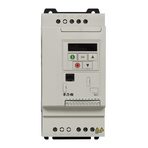
L1 /L L2 /N FW D PW R 9 10 11 IP20 degree of protection IP66 degree of protection, without IP66 degree of protection, with local local controls controls Figure 1: Designs, enclosure versions DC1 variable frequency drive 12/13 MN04020003Z-EN www.eaton.com... -
Page 18: System Overview
Integrable DX-BR… braking resistance (only for IP20, FS2 and FS3) d DXC-EXT-… expansion module e DX-NET-SWD3 SmartWire-DT interface (only in IP20) f DX-COM-STICK communication module and accessories (e. g. DX-CBL-… connection cable) g DE-KEY-… keypad (external) DC1 variable frequency drive 12/13 MN04020003Z-EN www.eaton.com... -
Page 19: Checking The Delivery
Open the packaging with adequate tools and inspect the contents immedi- ately after receipt in order to ensure that they are complete and undamaged. DC1 variable frequency drive 12/13 MN04020003Z-EN www.eaton.com... - Page 20 IL04020013Z for devices with an IP66 degree of protection • A data carrier (CD-ROM) containing documentation for the variable frequency drives L1 /L L2 /N 9 10 11 Figure 4: Equipment supplied DC1 variable frequency drive 12/13 MN04020003Z-EN www.eaton.com...
-
Page 21: Rated Operational Data
Read the manual (in this case MN04020003Z-EN) before making any electrical connections and commissioning. IP20/Open type Degree of protection of the housing: IP 20, UL (cUL) Open Type 25072012 Manufacturing date: 25.07.2012 DC1 variable frequency drive 12/13 MN04020003Z-EN www.eaton.com... -
Page 22: Key To Part Numbers
S = Single-phase mains connection / single-phase motor connection Device series DC1 = variable frequency drive, compact, Series 1 (D = Drives, C = Compact, 1 = Series) Figure 5: Key to part numbers 1) Please refer to manual MN04020004Z-EN DC1 variable frequency drive 12/13 MN04020003Z-EN www.eaton.com... - Page 23 IEC/EN 61800-3 in order to comply with the relevant limits concerning electromagnetic compatibility (EMC). → In accordance with IEC/EN 61800-3, an external radio interfer- ence suppression filter is required for DC1-…Nx-… models. DC1 variable frequency drive 12/13 MN04020003Z-EN www.eaton.com...
-
Page 24: Designations For The Elements In Variable Frequency Drives With An Ip20 Degree Of Protection
Cutout for mounting on mounting rail d Connection terminals in power section (motor feeder) e Control signal terminals (plug-in) f Communication interface (RJ45) g Operating unit with 5 control buttons and LED display h Info card DC1 variable frequency drive 12/13 MN04020003Z-EN www.eaton.com... -
Page 25: Designations For The Elements In Variable Frequency Drives With An Ip66 Degree Of Protection
Connection terminals in power section (mains side) and cableway for cable gland i Communication interface (RJ45) The info card and three additional knockouts for cable glands are found under the lower terminal cover. DC1 variable frequency drive 12/13 MN04020003Z-EN www.eaton.com... -
Page 26: Features
Braking chopper for external braking resistance (DC+ and BR connection only in FS2 and FS3 sizes) g Inverter. The IGBT based inverter converts the DC voltage of the DC link (U ) into a three-phase AC voltage (U ) with variable amplitude and frequency (f DC1 variable frequency drive 12/13 MN04020003Z-EN www.eaton.com... - Page 27 DC1-34…: 0.75 - 11 kW (400 V, 50 Hz) or 1 - 15 HP (460 V, 60 Hz) j Control section with operating unit and control buttons, seven-segment display, control voltage, plug-in control signal terminals k RJ45 interface for the computer and fieldbus connection (OP bus, Modbus RTU, CANopen) DC1 variable frequency drive 12/13 MN04020003Z-EN www.eaton.com...
-
Page 28: Selection Criteria
If necessary, for damp- ening and compensating the deviating current values, motor reactors or sine filters must be installed between the variable frequency drive and the motor. DC1 variable frequency drive 12/13 MN04020003Z-EN www.eaton.com... -
Page 29: Proper Use
(bypass). Observe the technical data and connection requirements. For additional information, refer to the equipment rating plate or label of the variable frequency drive and the documentation. Any other usage constitutes improper use. DC1 variable frequency drive 12/13 MN04020003Z-EN www.eaton.com... -
Page 30: Maintenance And Inspection
Relative average air humidity: < 95 %, non condensing (EN 50178), • To prevent damage to the RASP DC link capacitors, storage times longer than 12 months are not recommended (→ Section 1.12, „Charging the internal DC link capacitors“). DC1 variable frequency drive 12/13 MN04020003Z-EN www.eaton.com... -
Page 31: Charging The Internal Dc Link Capacitors
If some of the information printed on the rating plate is not legible, please state only the data which are clearly legible. Information concerning the guarantee can be found in the Terms and Conditions Eaton Industries GmbH. 24-hour hotline: +49 (0)1805 223 822 E-Mail: AfterSalesEGBonn@eaton.com DC1 variable frequency drive 12/13 MN04020003Z-EN www.eaton.com... - Page 32 1 DC1 device series 1.13 Service and warranty DC1 variable frequency drive 12/13 MN04020003Z-EN www.eaton.com...
-
Page 33: Engineering
Motor protection; Thermistor overload relay for machine protection i Cable lengths, motor cables, shielding (EMC) j Motor and application, parallel operation of multiple motors on a variable frequency drive, bypass circuit; DC braking k Braking resistance; dynamic braking DC1 variable frequency drive 12/13 MN04020003Z-EN www.eaton.com... -
Page 34: Electrical Power Network
If a DC1 variable frequency drive is connected to a corner-grounded system or to an IT system (ungrounded, insulated), the internal radio interference suppression filter must be disconnected (by unscrewing the screw marked EMC – in DC1-…-A20N only). DC1 variable frequency drive 12/13 MN04020003Z-EN www.eaton.com... -
Page 35: Mains Voltage And Frequency
In variable frequency drives powered with a three-phase power supply, these unbal- ances may cause the diodes in the mains rectifier to be loaded unevenly, resulting in premature diode failure. DC1 variable frequency drive 12/13 MN04020003Z-EN www.eaton.com... -
Page 36: Total Harmonic Distortion (Thd)
In the project planning for the connection of variable frequency drives to AC supply systems with undefined circumstances, consider using main chokes. DC1 variable frequency drive 12/13 MN04020003Z-EN www.eaton.com... -
Page 37: Mains Chokes
) of the variable frequency drive. The mains chokes recommended for DC1 variable frequency drives are listed in the annex (→ Table 32 and → Table 33) (→ Section 11.16, „Mains chokes“, page 215). DC1 variable frequency drive 12/13 MN04020003Z-EN www.eaton.com... -
Page 38: Sine Filter
Require more space inside the control panel NOTICE sine filters must only be used with permanently set pulse frequencies. → For more information on sine filters, please refer to → Section 11.18, „Sine filter“, page 219. DC1 variable frequency drive 12/13 MN04020003Z-EN www.eaton.com... -
Page 39: Safety And Switching
The specified minimum PE conductor cross-sections (EN 50178, VDE 0160) must be maintained. A completely (360°) screened low impedance cable on the motor side is required. The length of the motor cable depends on the RFI class and the environment. DC1 variable frequency drive 12/13 MN04020003Z-EN www.eaton.com... -
Page 40: Residual Current Circuit-Breaker (Rcd)
• height of the pulse frequency (switching frequency of the inverter), • design of the radio interference suppression filter • grounding measures at the site of the motor. DC1 variable frequency drive 12/13 MN04020003Z-EN www.eaton.com... -
Page 41: Mains Contactors
Measures must be taken to remove or minimize emission in the associated environment. He must also utilize means to increase the interference immu- nity of the devices of the system. DC1 variable frequency drive 12/13 MN04020003Z-EN www.eaton.com... - Page 42 The required EMC measures should be taken into account in the engineering phase. Improvements and modifications during mounting and installation or even at the installation site involve additional and even considerably higher costs. DC1 variable frequency drive 12/13 MN04020003Z-EN www.eaton.com...
-
Page 43: Motor
In order to reduce the amount of current distortion, a motor choke should be used at the variable frequency drive's output (→ Table 34, page 218 and → Table 35, page 218). DC1 variable frequency drive 12/13 MN04020003Z-EN www.eaton.com... -
Page 44: Circuit Types With Three-Phase Motors
0,75 KW 1410 mi n 50 Hz Figure 14: Example of a motor rating plate V1 W1 V1 W1 W2 U2 W2 U2 Figure 15: Configuration types: Star-connected circuit (left), Delta circuit (right) DC1 variable frequency drive 12/13 MN04020003Z-EN www.eaton.com... -
Page 45: 87-Hz Characteristic Curve
Figure 16: V/Hz characteristic curve for the rating plate of the motor from → Figure 14 a Star connection: 400 V, 50 Hz b Delta circuit: 230 V, 50 Hz c Delta connection: 400 V, 87 Hz DC1 variable frequency drive 12/13 MN04020003Z-EN www.eaton.com... -
Page 46: Connecting Ex Motors
Temperature monitors in the motor windings (thermistor, Thermo-Click) must not be connected directly to the variable frequency drive, but instead must be connected through a relay approved for the hazardous location (e.g. EMT6). DC1 variable frequency drive 12/13 MN04020003Z-EN www.eaton.com... -
Page 47: Installation
The filters must be main- tained and cleaned if necessary. • An appropriate enclosed control panel (without ventilation openings) must be used in environments containing large percentages or amounts of humidity, salt, or chemicals. DC1 variable frequency drive 12/13 MN04020003Z-EN www.eaton.com... -
Page 48: Mounting Position
1 2 3 4 5 6 7 8 9 10 11 Figure 18: Clearances for air cooling (left: IP20; right: IP66) → The variable frequency drives can be mounted side by side without any lateral clearance between them. DC1 variable frequency drive 12/13 MN04020003Z-EN www.eaton.com... - Page 49 +50 °C, an installation altitude of up to 1,000 m, and a pulse frequency of up to 8 kHz. → Typical heat loss makes up about 3% of the operational load conditions. DC1 variable frequency drive 12/13 MN04020003Z-EN www.eaton.com...
-
Page 50: Fixing
183. → Use screws with a washer and split washer with the permis- sible tightening torque of 1 Nm in order to protect the enclosure while safely and reliably mounting the device. DC1 variable frequency drive 12/13 MN04020003Z-EN www.eaton.com... - Page 51 3 Installation 3.2 Mounting Figure 21: Mounting dimensions Figure 22: Mounting preparation ▶ First fit the screws at the specified positions, mount the variable frequency drive and then fully tighten all screws. DC1 variable frequency drive 12/13 MN04020003Z-EN www.eaton.com...
- Page 52 (15 mm) preferably. ▶ To do this, place the variable frequency drive on the mounting rail from above [1] and press it down until it snaps into place [2]. Figure 24: Fixing on mounting rails DC1 variable frequency drive 12/13 MN04020003Z-EN www.eaton.com...
- Page 53 A flat-bladed screwdriver (blade width 5 mm) is recommended for pushing down the clip. f 5 mm (f 0.197“) Figure 25: Dismantling from mounting rails DC1 variable frequency drive 12/13 MN04020003Z-EN www.eaton.com...
-
Page 54: Installing Cable Glands (Ip66)
Figure 26: Punching out the knockouts ▶ Remove the lower housing cover as shown. PZ 2 Figure 27: Removing the lower housing cover DC1 variable frequency drive 12/13 MN04020003Z-EN www.eaton.com... - Page 55 2 x PG 16 2 x M25 GHG9601955R0004 CAP189252 (10 - 18 mm) GHG9061941R0034 CAP189562 (6 - 13 mm) DKA13E 1) Part nos. for glands available from Cooper Crouse-Hinds GmbH provided as an example DC1 variable frequency drive 12/13 MN04020003Z-EN www.eaton.com...
- Page 56 PE. 1 2 3 4 5 6 7 8 9 10 11 ⏚ ⏚ L1/N L2/N Figure 29: Grounding the EMC cable gland Figure 30: Schematic diagram of EMC gland assembly DC1 variable frequency drive 12/13 MN04020003Z-EN www.eaton.com...
-
Page 57: Emc Installation
(anodized, yellow chromated). An overview of all EMC measures is provided in Figure 31 on Page 53. → Install the variable frequency drive as directly as possible (without spacers) on a metal plate (mounting plate). DC1 variable frequency drive 12/13 MN04020003Z-EN www.eaton.com... - Page 58 (90 degrees). → Never lay control- or signal cables in the same duct as power cables. Analog signal cables (measured, reference and correc- tion values) must be screened. DC1 variable frequency drive 12/13 MN04020003Z-EN www.eaton.com...
- Page 59 Mounting surfaces of variable frequency drive and cable screen must be free from paint. Cable screen of cables at variable frequency drive’s output with earth potential (PES) across large surface area Large-area cable screen contacts with motor. Large-area earth connection of all metallic parts. DC1 variable frequency drive 12/13 MN04020003Z-EN www.eaton.com...
- Page 60 W2 U2 W2 U2 W2 U2 (≧ 11.81“) ① Power: L1, L2, L3, N, PE, U, V, W, DC+, BR ② Control: 1, 2, … 11, Modbus, CANopen = 230 V = 400 V DC1 variable frequency drive 12/13 MN04020003Z-EN www.eaton.com...
-
Page 61: Emc Screw
In connections to isolated power sources (IT networks), the EMC screw should be removed. The earth fault monitors required for IT networks must be suitable for operation with power electronic devices (IEC 61557-8). DC1 variable frequency drive 12/13 MN04020003Z-EN www.eaton.com... -
Page 62: Screen Earth Kit
Avoid ground loops when installing multiple variable frequency drives in one control panel. Make sure that all metallic devices that are to be grounded have a broad area connection with the mounting plate. DC1 variable frequency drive 12/13 MN04020003Z-EN www.eaton.com... -
Page 63: Protective Earth
NOTICE The screw labeled VAR (→ Figure 33, page 55) must not be manipulated as long as the variable frequency drive is connected to the mains. DC1 variable frequency drive 12/13 MN04020003Z-EN www.eaton.com... -
Page 64: Electrical Installation
(5) minutes after the supply voltage has been switched off (intermediate circuit capacitor discharging time). Pay attention to hazard warnings! → Perform the steps below with the specified insulated tools and without using force. DC1 variable frequency drive 12/13 MN04020003Z-EN www.eaton.com... -
Page 65: Connection To Power Section
The number and the arrangement of the connection terminals used depend on the variable frequency drive's size and model. NOTICE The variable frequency drive must always be connected with ground potential via a grounding conductor (PE). DC1 variable frequency drive 12/13 MN04020003Z-EN www.eaton.com... - Page 66 • DC1-34… (400 V, 480 V) L1/L L2/N Motor connection for three-phase motors: ⏚ • DC1-1D… (230 V) • DC1-12… (230 V) • DC1-32… (230 V) • DC1-34… (400 V, 460 V) Optional: External braking resistance (R DC1 variable frequency drive 12/13 MN04020003Z-EN www.eaton.com...
- Page 67 • DC1-32… (230 V) • DC1-34… (400 V, 460 V) Optional: External braking resistance (R → Terminal + has the same function as terminal DC+ in devices with an IP20 degree of protection. DC1 variable frequency drive 12/13 MN04020003Z-EN www.eaton.com...
- Page 68 EMC interference, this twisted screen connection should be as short as possible (recommended value for the twisted cable screen: b ≧ 1/5 a). 15 mm (0.59’’) Figure 35: Screened motor connection cable DC1 variable frequency drive 12/13 MN04020003Z-EN www.eaton.com...
- Page 69 Connection examples Figure 36: Connection example DX-EMC-MNT ... N FS1, FS2: = 4 x M4 FS3: = 4 x M5 1.3 Nm (11.5 lb-in) DX-EMC-MNT ... M Figure 37: EMC mounting bracket DC1 variable frequency drive 12/13 MN04020003Z-EN www.eaton.com...
- Page 70 (PES) with a large area connection. Free or non-screened connection cables should not be any longer than about 300 mm. DC1 variable frequency drive 12/13 MN04020003Z-EN www.eaton.com...
- Page 71 Figure 40: Stripping lengths in the power section Frame size [mm] [in] 0.39 0.39 Mains = Electrical supply system Motor = Motor connection DC link = Internal DC link Brake resistor = Braking chopper DC1 variable frequency drive 12/13 MN04020003Z-EN www.eaton.com...
-
Page 72: Connection On Control Section
Figure 42: Connecting example with insulated control cable end and cable screen earthing (PES) → Prevent the screen from becoming unbraided, e.g. by pushing the split plastic sheath over the end of the screen or with a rubber grommet on the end of the screen. DC1 variable frequency drive 12/13 MN04020003Z-EN www.eaton.com... - Page 73 In the case of devices with an IP66 degree of protection and local controls (DC1-…-A6SN), the local controls (setpoint potentiometer and operating direction selector switch) will already be wired to the control signal terminal strip. DC1 variable frequency drive 12/13 MN04020003Z-EN www.eaton.com...
- Page 74 The terminal capacities and stripping lengths are listed in the following table. Table 8: Control signal terminal sizes and designs ft-lbs 0.2 - 2.5 0.2 - 1.5 24 - 12 0.4 x 2.5 DC1 variable frequency drive 12/13 MN04020003Z-EN www.eaton.com...
- Page 75 Maximum switching load: 250 V AC/6 A or 30 V DC/5 A → The control signal terminals' functions and electrical parameters can be changed with • Parameter, • DXC-EXT-… expansion modules (see annex) DC1 variable frequency drive 12/13 MN04020003Z-EN www.eaton.com...
- Page 76 Control signal terminal 8 can be used as a digital or as an analog output. It is used as an analog output (AO) in the default configuration that comes with the variable frequency drive when it is delivered. Figure 46: Control signal terminals (digital / analog) DC1 variable frequency drive 12/13 MN04020003Z-EN www.eaton.com...
- Page 77 The output signal is adjusted with parameter P-25 (→ Page 119). Figure 47: Analog output (AO) (connecting example) → Control signal terminals 7 and 9 are the common 0 V reference potential for all analog and digital input signals. DC1 variable frequency drive 12/13 MN04020003Z-EN www.eaton.com...
- Page 78 (DI1 to DI4) and integrate them directly into control circuits with 110 V / 230 V. Values of 80 to 110/230 V AC will be recognized as a high signal. DC1 variable frequency drive 12/13 MN04020003Z-EN www.eaton.com...
- Page 79 The relay function can be configured with parameter P-18 (→ Table 37, Page 223). The electrical connection specifications for control signal terminals 10 and 11 are: • 250 V AC, max. 6 A • 30 V DC, max. 5 A DC1 variable frequency drive 12/13 MN04020003Z-EN www.eaton.com...
- Page 80 (PIN 1) RS485 RJ45 9 10 11 Figure 50: RJ 45 interface → DC1 variable frequency drives do not have an internal bus termi- nation resistor. Use DX-CBL-TERM or EASY-NT-R if necessary. DC1 variable frequency drive 12/13 MN04020003Z-EN www.eaton.com...
-
Page 81: Block Diagrams
(→ Section 3.5.2, „Connection on control section“, page 66). The RJ45 interface used for field bus or OP bus communications is shown at the very right (→ Section 8.1.1, „Communications“, page 135). DC1 variable frequency drive 12/13 MN04020003Z-EN www.eaton.com... - Page 82 ① FS2 devices allow for the connection of braking resistances. → DC1-1D…Nx-… variable frequency drives do not have an internal radio interference suppression filter. An external radio interference suppression filter is required for operation in accordance with EN 61800-3. DC1 variable frequency drive 12/13 MN04020003Z-EN www.eaton.com...
- Page 83 ④ External braking resistances can be connected to devices with a size of FS2 or bigger → DC1-1D…Nx-A6SN variable frequency drives do not have an internal radio interference suppression filter. An external radio interference suppression filter is required for operation as per EN 61800-3. DC1 variable frequency drive 12/13 MN04020003Z-EN www.eaton.com...
- Page 84 3 AC 230 V Figure 53: DC1-12… block diagram Variable frequency drive with single-phase supply system voltage and three-phase motor connection ① FS2 and FS3 make it possible to connect external braking resistances. DC1 variable frequency drive 12/13 MN04020003Z-EN www.eaton.com...
- Page 85 FS2 and FS3 devices allow for the connection of external braking resistances. ① Setpoint potentiometer ② Operating direction selector switch ③ Mains transfer switch ④ External braking resistances can be connected to devices with a size of FS2 or bigger DC1 variable frequency drive 12/13 MN04020003Z-EN www.eaton.com...
- Page 86 3 AC 230/400/460 V Figure 55: DC1-32…, DC1-34… block diagram variable frequency drive with three-phase mains supply voltage and three-phase motor connection ① FS2 and FS3 make it possible to connect external braking resistances. DC1 variable frequency drive 12/13 MN04020003Z-EN www.eaton.com...
- Page 87 FS2 and FS3 devices allow for the connection of external braking resistances. ① Setpoint potentiometer ② Operating direction selector switch ③ Mains transfer switch ④ External braking resistances can be connected to devices with a size of FS2 or bigger DC1 variable frequency drive 12/13 MN04020003Z-EN www.eaton.com...
-
Page 88: Insulation Test
1000 V. The insulation resistance must be greater than 1 MΩ. → Consider the notes from the motor manufacturer in testing the insulation resistance. DC1 variable frequency drive 12/13 MN04020003Z-EN www.eaton.com... -
Page 89: Operation
(→ Table 37, page 221). The effective direction of a coupled machine will allow the motor to start. All emergency switching off functions and safety functions are in an appropriate condition. DC1 variable frequency drive 12/13 MN04020003Z-EN www.eaton.com... -
Page 90: Operational Hazard Warnings
DANGER Following a shutdown (fault, mains voltage off), the motor can start automatically (when the supply voltage is switched back on) if the automatic restart function has been enabled (→ parameters P-31). DC1 variable frequency drive 12/13 MN04020003Z-EN www.eaton.com... -
Page 91: Commissioning With Control Signal Terminals (Default Settings)
You can skip this section if you want to set up the parameters directly for optimal operation of the variable frequency drive based on the motor data (rating plate) and the application. Following are a series of simplified connecting examples that use the default configuration: DC1 variable frequency drive 12/13 MN04020003Z-EN www.eaton.com... - Page 92 Terminal 1: FWD = Clockwise rotating field (Forward Run) • Terminal 2: REV = Counterclockwise rotating field (Reverse Run) The FWD and REV control commands are interlocked (exclusive OR) and require a rising voltage edge. DC1 variable frequency drive 12/13 MN04020003Z-EN www.eaton.com...
- Page 93 Information on settings and the description of the parameters used here is provided in section “Drives control”, Page 105. +24 V STOP P-07 = 50 Hz ① P-03 = 5 s Figure 57: Start-Stop command with maximum setpoint value voltage, acceleration ramp 5 s DC1 variable frequency drive 12/13 MN04020003Z-EN www.eaton.com...
-
Page 94: Commissioning With Local Controls (Ip66)
Setpoint value voltage +10 V (Output, maximum 10 mA) Frequency reference value f-Set (Input 0 – +10 V) ① Reference potential (0 V) ① Make sure that the enable contacts (FWD/REV) are open before switching on the mains voltage. DC1 variable frequency drive 12/13 MN04020003Z-EN www.eaton.com... - Page 95 ① (0 - +10 V proportional voltage signal). The change in output frequency here is delayed based on the specified acceleration and deceleration ramps. When using the device's default settings, these times will be set to 5 seconds. DC1 variable frequency drive 12/13 MN04020003Z-EN www.eaton.com...
-
Page 96: Commissioning With Keypad
2 in order to get a start enable. Press the Stop pushbutton in order to get to the setpoint input display automatically. Use the ▲ and ▼ arrow keys to change the setpoint value. DC1 variable frequency drive 12/13 MN04020003Z-EN www.eaton.com... - Page 97 When the REV operating direction is in effect, the frequency will have a minus sign. Minus sign for REV operating direction When the Stop pushbutton is pressed, the variable frequency drive will be stopped with the deceleration time configured in P-04. DC1 variable frequency drive 12/13 MN04020003Z-EN www.eaton.com...
-
Page 98: Commissioning With Field Bus / Smartwire-Dt
→ For more information, please refer to chapters 7 and 8. For more information on SmartWire-DT, please refer to manual MN04012009Z, "DX-NET-SWD. SmartWire-DT Interface Card for DC1 Variable Frequency Drives." DC1 variable frequency drive 12/13 MN04020003Z-EN www.eaton.com... -
Page 99: Parameters
• Increase output frequency / motor speed if P-12 = 1 or P-12 = 2 • Decrement numeric value or parameter number • Reduce output frequency / motor speed if P-12 = 1 or P-12 = 2 DC1 variable frequency drive 12/13 MN04020003Z-EN www.eaton.com... -
Page 100: Shortcuts
When the specified supply voltage (L1/L, L2/N, L3 connection terminals) is applied, the DC1 variable frequency drive will automatically perform a self- test: The LED display will light up and, depending on the selected operating mode, will display Stop or the appropriate value. DC1 variable frequency drive 12/13 MN04020003Z-EN www.eaton.com... -
Page 101: Setting Parameters
5.2.3 Field bus/SmartWire DT A DC1 variable frequency drive's parameters can be configured via a field bus orSmartWire-DT. → For more information, please refer to chapters 7 and 8 and to manual MN04012009Z-EN. DC1 variable frequency drive 12/13 MN04020003Z-EN www.eaton.com... -
Page 102: List Of Parameters
P-14 will be shown. To access the extended parameter set, enter 101 (= WE and P-37) for parameter P-14. P-01 P-01 P-02 P-02 P-03 P-03 P-14 P-14 P-15 P-16 P-53 Figure 60: Parameter Access DC1 variable frequency drive 12/13 MN04020003Z-EN www.eaton.com... -
Page 103: Parameter Lock
"P-dEf" is shown on the display. → The fault log (P-13) and the monitor log will not be restored to their default settings when the parameters are reset! DC1 variable frequency drive 12/13 MN04020003Z-EN www.eaton.com... -
Page 104: I/0 Control
FWD switch position will drive DI1 and the REV switch position will drive DI2. → The FWD and REV designations refer to the default settings. The above functions may change if changes are made to the P-15 parameter. DC1 variable frequency drive 12/13 MN04020003Z-EN www.eaton.com... -
Page 105: Digital And Analog Inputs
DI3 can become AI2; AI1 can become DI4. The following tables show how parameter P-15 depends on parameter P-12. → For the button commands, please note that stop commands are run as N/C contact commands. DC1 variable frequency drive 12/13 MN04020003Z-EN www.eaton.com... - Page 106 Negative fixed frequencies are inverted it Run REV is selected. 1) FWD switch position only for IP66 degree of protection with local controls 2) REV switch position only for IP66 degree of protection with local controls 3) Button command DC1 variable frequency drive 12/13 MN04020003Z-EN www.eaton.com...
- Page 107 DI3. 1 = Enable 1) FWD switch position only for IP66 degree of protection with local controls 2) REV switch position only for IP66 degree of protection with local controls 3) Button command DC1 variable frequency drive 12/13 MN04020003Z-EN www.eaton.com...
- Page 108 Negative fixed frequencies are inverted it Run REV is selected. 1) FWD switch position only for IP66 degree of protection with local controls 2) REV switch position only for IP66 degree of protection with local controls 3) Button command DC1 variable frequency drive 12/13 MN04020003Z-EN www.eaton.com...
-
Page 109: Operational Data Indicator
(undervoltage does not count as a trip) – Not reset when mains power is switched off/on unless a trip occurred before the mains power was switched off. DC1 variable frequency drive 12/13 MN04020003Z-EN www.eaton.com... - Page 110 Control signal terminal 2 actuated (DI1) 0100 Control signal terminal 3 actuated (DI2) 0010 Control signal terminal 4 actuated (DI3) 0001 Control signal terminal 6 actuated (DI4) 0101 Control signal terminals 3 and 6 actuated (DI2 + DI4) DC1 variable frequency drive 12/13 MN04020003Z-EN www.eaton.com...
-
Page 111: Drives Control
In addition, an enable signal via DI1 and an enable setpoint via DI2 → If the control level changes, the inputs' mode of operation and function (P-15) via the control signal terminals will change. DC1 variable frequency drive 12/13 MN04020003Z-EN www.eaton.com... -
Page 112: Second Acceleration And Deceleration Time
Deceleration time (dec1) P-09 – 25 - 500 Hz Rated motor frequency (→ motor rating plate) 50.0 Note: This parameter value is also automatically applied as the cut-off frequency for the V/Hz characteristic curve. DC1 variable frequency drive 12/13 MN04020003Z-EN www.eaton.com... -
Page 113: Stop Function With Two Different Deceleration Times
DI1 and DI2 (control signal terminals 2 and 3) simultaneously. Access rights Value Description ro/rw P-04 ✓ 0.1 - 600 s Deceleration time (dec1) P-24 ✓ 0.1 - 25.0 s Second deceleration time (dec2) DC1 variable frequency drive 12/13 MN04020003Z-EN www.eaton.com... -
Page 114: Motor
4 A as per rating plate in Figure 64). See in the default settings. Required changes for electrically mapping the motor: P-07 = 230, P-08 = 4.0, P-09 = 50 DC1 variable frequency drive 12/13 MN04020003Z-EN www.eaton.com... -
Page 115: 87-Hz Characteristic Curve
(→ Motor rating plate) P-09 – 25 - 500 Hz Rated motor frequency 50.0 (→ Motor rating plate) Note: This parameter value is also automatically applied as the cut-off frequency for the V/Hz characteristic curve. DC1 variable frequency drive 12/13 MN04020003Z-EN www.eaton.com... - Page 116 All speed-related parameters (such as the minimum and maximum frequencies and the fixed frequencies) will also be shown in rpm. DC1 variable frequency drive 12/13 MN04020003Z-EN www.eaton.com...
-
Page 117: U/F Characteristic Curve
(nominal motor voltage) and P-09 (rated motor frequency). P-07 P-07 P-28 P-11 P-11 f [Hz] f [Hz] P-02 P-09 P-29 P-09 linear parameterizable P-28 = 0, P-29 = 0 P-28 > 0, P-29 > 0 Figure 66: U/f-characteristic curve DC1 variable frequency drive 12/13 MN04020003Z-EN www.eaton.com... -
Page 118: Speed Behavior Without Slip Compensation
In controlled operation (V/F characteristic curve), the variable frequency drive cannot compensate this load-related speed difference. The speed behavior of the motor corresponds to that of a motor in a constant AC supply system. Figure 67: Speed behavior Without slip compensation DC1 variable frequency drive 12/13 MN04020003Z-EN www.eaton.com... -
Page 119: Speed Behavior With Slip Compensation
The simple illustration shows that, as the load torque increases (①), the resulting speed reduction is compensated by an increase in the output frequency (②) (→ Figure 69). Figure 69: Speed behavior with slip compensation DC1 variable frequency drive 12/13 MN04020003Z-EN www.eaton.com... - Page 120 P-28 – 0.00 - P-07 V V/Hz characteristic curve modification voltage P-29 – 0.00 - P-09 Hz V/Hz characteristic curve modification frequency DC1 variable frequency drive 12/13 MN04020003Z-EN www.eaton.com...
-
Page 121: Braking
Nor for intermediate braking. NOTICE DC braking will cause increased motor heating. Accordingly, make sure to configure a braking torque that is as low as possible using the voltage amplification (P-11) and braking duration (P-32) parameters. DC1 variable frequency drive 12/13 MN04020003Z-EN www.eaton.com... -
Page 122: Regenerative Braking
② ③ ① ˜ Figure 70: Regenerative braking with external braking resistance a Machine flywheel mass b Inverter with brake chopper (braking transistor) c Braking resistance (R ) → Energy flow (braking torque) DC1 variable frequency drive 12/13 MN04020003Z-EN www.eaton.com... -
Page 123: Mechanical Brake (Actuation)
250 VAC / 6 A or 30 VDC / 5 A, P18 = 6 STOP P-05 = 2 [Hz] P-19 (FWD/REV) (P-18 = 6) ① ② Figure 71: External brake actuated via K1 a Brake, released b Brake activates and brakes the drive mechanically. DC1 variable frequency drive 12/13 MN04020003Z-EN www.eaton.com... - Page 124 Output current < limit value (P-19) P-19 ✓ K1-Limit value (relay) 100.0 P-02 - 200.0 % The adjustable limit value that is being used in connection with settings 4 to 7 of P-18 and P-25 DC1 variable frequency drive 12/13 MN04020003Z-EN www.eaton.com...
- Page 125 Activated P-34 ✓ Brake chopper activation (only with sizes FS2 and FS3) Locked Enabled with overload protection braking resistance (for integrable braking resistances) Enabled without overload protection braking resistance (for external braking resistances) DC1 variable frequency drive 12/13 MN04020003Z-EN www.eaton.com...
- Page 126 6 Drives control 6.4 Braking DC1 variable frequency drive 12/13 MN04020003Z-EN www.eaton.com...
-
Page 127: Applications
DI2 (control signal terminal 3): AI1/AI2 (change of setpoint source from AI1 to AI2) • AI1 (control signal terminal 6): analog setpoint value 1 • AI2 (control signal terminal 4): analog setpoint value 2 DC1 variable frequency drive 12/13 MN04020003Z-EN www.eaton.com... -
Page 128: Scaled Value Range (Ai1)
Analog input 1 will be scaled by this factor Example: For P-16 and a 0 -10 V signal and a scaling factor of 200.0%, a 5-V input will make the variable frequency drive run at the maximum frequency / speed (P-01). DC1 variable frequency drive 12/13 MN04020003Z-EN www.eaton.com... -
Page 129: External Fault (Ext)
P-15 = 7 Figure 75: Thermistor connection → The switching threshold for the external fault input is fixed and cannot be changed: Fault when ≧ 2.5 kΩ; reset fault when ≦ 1.9 kΩ DC1 variable frequency drive 12/13 MN04020003Z-EN www.eaton.com... -
Page 130: Fixed Frequency Setpoint Values
Figure 76: Example: fixed frequencies FF1 to FF4 Example P-12 = 0; P-15 = 9; P-21 = 20; P-22 = 30; P-23 = 40 Fixed frequency FF1 (P-20) FF2 (P-21) FF3 (P-22) FF4 (P-23) DC1 variable frequency drive 12/13 MN04020003Z-EN www.eaton.com... -
Page 131: Frequency Jump
①. 7.4.2 Frequency jump In systems with mechanical resonances, you can skip this frequency range for stationary operation. [Hz] ① ② Figure 78:Setting range for frequency masking a P-26 b P-27 DC1 variable frequency drive 12/13 MN04020003Z-EN www.eaton.com... - Page 132 If the frequency reference value applied to the variable frequency drive falls within the band, the output frequency will remain at the upper or lower limit of the band. DC1 variable frequency drive 12/13 MN04020003Z-EN www.eaton.com...
-
Page 133: Motor Potentiometer
P-04 (dec1) all the way to 0 Hz if a minimum frequency has not been set in P-02. → For more information, please refer to application note AP040042. DC1 variable frequency drive 12/13 MN04020003Z-EN www.eaton.com... - Page 134 (P-01). The frequency will not fall below the minimum frequency value unless the start enable (DI1) is switched off. [Hz] P-01 P-02 0 Hz DOWN START Figure 81: Motor potentiometer with f limit DC1 variable frequency drive 12/13 MN04020003Z-EN www.eaton.com...
- Page 135 The variable frequency drive will be started directly from the control signal terminals; the keypad's start and stop buttons will be ignored. The variable frequency drive will always start with the most recent operating frequency/speed (P-02). DC1 variable frequency drive 12/13 MN04020003Z-EN www.eaton.com...
-
Page 136: Motor Current Monitoring
Output frequency = frequency reference value Error message (variable frequency drive not ready) Output frequency ≧ limit value (P-19) Output current ≧ limit value (P-19) Output frequency < limit value (P-19) Output current < limit value (P-19) DC1 variable frequency drive 12/13 MN04020003Z-EN www.eaton.com... - Page 137 Output current < limit value (P-19) Analog output → 0 - 10 V DC (value 8, 9) Output frequency f-Out → 0 - 100 % f (P-01) Output current → 0 - 200 % I (P-08) DC1 variable frequency drive 12/13 MN04020003Z-EN www.eaton.com...
-
Page 138: Autostart Function
The variable frequency drive will start automatically twice. AVto-2 The variable frequency drive will start automatically three times. AVto-3 The variable frequency drive will start automatically four times. AVto-4 The variable frequency drive will start automatically five times. AVto-5 DC1 variable frequency drive 12/13 MN04020003Z-EN www.eaton.com... -
Page 139: Setpoint Input Via Keypad
Connect control signal terminal 1 to control signal terminal 2 in order to get a start enable. Press the STOP pushbutton in order to get to the setpoint input display automatically. Use the ▲ and ▼ arrow keys to change the setpoint value. DC1 variable frequency drive 12/13 MN04020003Z-EN www.eaton.com... - Page 140 When the REV operating direction is in effect, the frequency will have a minus sign. Minus sign for REV operating direction When the Stop pushbutton is pressed, the variable frequency drive will be stopped with the deceleration time configured in P-04. DC1 variable frequency drive 12/13 MN04020003Z-EN www.eaton.com...
-
Page 141: Modbus Rtu
(slaves) . Each variable frequency drive has a unique address on the network. Addresses are assigned individually to each DC1 variable frequency drive with the P-36 parameter and are independent of their physical connection (position) within the network. DC1 variable frequency drive 12/13 MN04020003Z-EN www.eaton.com... -
Page 142: Com Port
8.1.4 Modbus data format The data format is fixed for DC1 variable frequency drives and cannot be changed. • 1 start bit • 8 data bits • 1 stop bit • No parity DC1 variable frequency drive 12/13 MN04020003Z-EN www.eaton.com... -
Page 143: Modbus Parameters
If P-36 = 0, the function will be disabled. "t" at the beginning means: error message and coasting "r" at the beginning means: stop with second braking ramp time DC1 variable frequency drive 12/13 MN04020003Z-EN www.eaton.com... - Page 144 SmartWire-DT control – control will depend on the configuration in the event of a loss of communications; automatic switch to local control Control commands and setpoint values via SmartWire-DT In addition, an enable signal via DI1 and an enable setpoint via DI2 DC1 variable frequency drive 12/13 MN04020003Z-EN www.eaton.com...
-
Page 145: Operating Mode Modbus Rtu
Data (N x 1 Byte) CRC (2 Bytes) Figure 87: Data exchange between master and slave → The variable frequency drive (slave) only sends a response if it has received a request from the master beforehand. DC1 variable frequency drive 12/13 MN04020003Z-EN www.eaton.com... -
Page 146: Structure Of The Master Request
While receiving the frame, the slave performs a new calculation and compares the calculated value to the actual value in the CRC field. If both values are not identical, an error is set. DC1 variable frequency drive 12/13 MN04020003Z-EN www.eaton.com... -
Page 147: Structure Of The Slave Response
If the time interval between the messages is less than 3.5. characters. → The master must be programmed to repeat the request if it does not receive a response within a specified time. DC1 variable frequency drive 12/13 MN04020003Z-EN www.eaton.com... -
Page 148: Modbus: Register Mapping
The input process data is used to control the DC1 variable frequency drive. Designation Scaling Factor Unit Field bus command – Binary code Field bus speed reference value Reserved – – Modbus ramp time 0.01 DC1 variable frequency drive 12/13 MN04020003Z-EN www.eaton.com... - Page 149 Field bus speed reference value (ID 2) The permissible values fall within a range of P-02 (min. frequency) to P-01 (max. frequency). This value is scaled with a factor of 0.1 in the application. DC1 variable frequency drive 12/13 MN04020003Z-EN www.eaton.com...
- Page 150 The variable frequency drive operating time since min/s the last fault Status and fault word (ID 6) Information regarding the device status and error messages is specified in the status and fault word. Fault word Statusword DC1 variable frequency drive 12/13 MN04020003Z-EN www.eaton.com...
- Page 151 The current is specified with one decimal place. Example: 34 ≙ 3.4 A. Status DIs (ID 11) This value indicates the digital inputs' state. The lowest bit indicates the state of DI 1. DC1 variable frequency drive 12/13 MN04020003Z-EN www.eaton.com...
- Page 152 Specifies the software version of the control section with two decimal places. Power section software version (ID 16) Specifies the software version of the power section with two decimal places. Variable frequency drive recognition (ID 17) The device's unique serial number. DC1 variable frequency drive 12/13 MN04020003Z-EN www.eaton.com...
-
Page 153: Explanation Of Function Code
Slave response: 01 03 02 0000 B844 Register [hex] Name Slave address Function code (reading of holding registers) Number of consecutive data bytes (1 register = 2 byte) 0000 Content (2 byte) for register 6: 0 B844 DC1 variable frequency drive 12/13 MN04020003Z-EN www.eaton.com... - Page 154 1: The ID of the register for the writing operation is 1, since the master controller has an offset of +1. 0001 Content (2 byte) for register 0000 0000 0000 001 → RUN B844 → Function code 06 can be used for a broadcast. DC1 variable frequency drive 12/13 MN04020003Z-EN www.eaton.com...
-
Page 155: Canopen
Controller Area Network COB ID Communication Object Identifier CONST Constant variable (read access only) Electronic Data Sheets EMCY Emergency Object Network Management Process Data Object Read Only Memory Receive Service Data Object Transmit DC1 variable frequency drive 12/13 MN04020003Z-EN www.eaton.com... -
Page 156: System Overview
All of the variable frequency drive's parameters can be transferred with CANopen by using the appropriate SDOs/PDOs. DC1 variable frequency drive 12/13 MN04020003Z-EN www.eaton.com... -
Page 157: Com Port
RS485- Modbus RTU (A) RS485+ Modbus RTU (B) Figure 89: Configuration of the RJ45 interface → If you are using an easy network, keep in mind that CAN- and CAN+ need to be swapped. DC1 variable frequency drive 12/13 MN04020003Z-EN www.eaton.com... -
Page 158: Enable
Table 17: Maximum cable length and baud rate Baud Rate Maximum cable length 125 kbit/s 500 m 250 kBit/s M 250 500 kBit/s 100 m 800 kBit/s 50 m 1000 kBit/s 30 m DC1 variable frequency drive 12/13 MN04020003Z-EN www.eaton.com... -
Page 159: Set Canopen User Address
DI1 and an enable setpoint via DI2) P-36 – Serial communication configuration 1 - 63 Variable frequency drive slave address Modbus RTU baud rate 9.6 kBit/s 19.2 Kbit/s 38.4 kBit/s 57.6 kBit/s 115.2 kBit/s DC1 variable frequency drive 12/13 MN04020003Z-EN www.eaton.com... - Page 160 30 ms r 100 ms r 1000 ms r 3000 ms P-50 – Baud 0 = 125 kBit/s 0 - 3 Rate 1 = 250 kBit/s 2 = 500 kBit/s 3 = 1000 kBit/s DC1 variable frequency drive 12/13 MN04020003Z-EN www.eaton.com...
-
Page 161: Transmission Type
Transmissions will be sent directly if there is a specific change. Received data will be processed directly. → When the device is running with its default configuration, the value will be set to 254, "Asynchronous – manufacturer- specific." DC1 variable frequency drive 12/13 MN04020003Z-EN www.eaton.com... -
Page 162: Object List
The latest version of the EDS file will be included in the CD-ROM enclosed with every DC1 variable frequency drive. It can also be downloaded from Eaton's website at: http://www.eaton.com/moeller → Support The object dictionary contains all the objects corresponding to a CANopen module. -
Page 163: Communication-Specific Objects
1018 Identity Object UNSIGNED8 General device information Vendor ID UNSIGNED32 000001CA Manufacturer: Eaton Industries GmbH Product Code UNSIGNED32 Product Number Revision Number UNSIGNED32 1.01 version (Example) Serial Number UNSIGNED32 00000001 Serial number (Example) DC1 variable frequency drive 12/13 MN04020003Z-EN www.eaton.com... -
Page 164: Server Sdo Parameter
Number of Mapped Application UNSIGNED8 Highest subindex used Objects 1st Mapping Object UNSIGNED32 20000010 2nd Mapping Object UNSIGNED32 20010010 3rd Mapping Object UNSIGNED32 20030010 1601 Number of Mapped Application UNSIGNED8 Highest subindex used Objects DC1 variable frequency drive 12/13 MN04020003Z-EN www.eaton.com... - Page 165 Tx PDO 2 Number of Mapped Application UNSIGNED8 Highest subindex used Objects 1st Mapping Object UNSIGNED32 20110010 2nd Mapping Object UNSIGNED32 20120010 3rd Mapping Object UNSIGNED32 20130010 4th Mapping Object UNSIGNED32 20140010 DC1 variable frequency drive 12/13 MN04020003Z-EN www.eaton.com...
-
Page 166: Manufacturer-Specific Objects
UNSIGNED16 Current operating time in hours 2041 Current run minute/second UNSIGNED16 Current operating time in minutes/seconds 2065 P-01 DC1 variable frequency drive parameters 2066 P-02 … … … … 2095 P-49 2096 P-50 DC1 variable frequency drive 12/13 MN04020003Z-EN www.eaton.com... - Page 167 The frequency reference value is specified in hertz with a single decimal place. Example: ≙ 25.8 Hz User ramp time (Index 2003 The user ramp time is specified in seconds with two decimal places. DC1 variable frequency drive 12/13 MN04020003Z-EN www.eaton.com...
- Page 168 The frequency reference value is specified in hertz with a single decimal place. Example: ≙ 12.5 Hz Current (Index 200D The current is specified with one decimal place. Example: 34 ≙ 3.4 A DC1 variable frequency drive 12/13 MN04020003Z-EN www.eaton.com...
-
Page 169: Error Messages
7-segment digital display assembly. → The values in the fault log (P-13) will not be deleted if the variable frequency drive is reset to its default settings! DC1 variable frequency drive 12/13 MN04020003Z-EN www.eaton.com... - Page 170 The two dots on the right will flash. The oldest error message will be shown after you press the ▲ arrow key (Up) once more. Example: V-Volt (undervoltage message) The three dots on the right will flash. DC1 variable frequency drive 12/13 MN04020003Z-EN www.eaton.com...
-
Page 171: Error List
• Mains undervoltage occurs during operation, check the power supply voltage. Overtemperature Heat sink overtemperature • Check the variable frequency drive's ambient air temperature. Check whether additional clear- ance or cooling is required. DC1 variable frequency drive 12/13 MN04020003Z-EN www.eaton.com... - Page 172 • The motor pick-up control function did not deter- SPIn-F fault catching spinning motors) failed mine the motor speed. Thermistor fault Defective thermistor on heat sink • Please contact your closest Eaton representa- th-Frt tive. Data error Internal memory error • Parameter not stored; restore default settings. dAtA-F •...
-
Page 173: Annex
The motor output designates the respective active power output to the drive shaft of a normal, four pole, internally or externally ventilated alternating current asynchronous motor with 1.500 rpm at 50 Hz or 1.800 rpm at 60 Hz. DC1 variable frequency drive 12/13 MN04020003Z-EN www.eaton.com... -
Page 174: Features
2) (1500 rpm at 50 Hz, 1800 rpm at 60 Hz). 3) Keep motor specifications in mind (6 A = normalized rated value in accordance with UL 580 C). 4) In certain cases, only operation with a reduced motor load may be possible. DC1 variable frequency drive 12/13 MN04020003Z-EN www.eaton.com... - Page 175 N, F IP20, IP66 DC1-34024… 21.7 N, F IP20 1) The rated motor currents apply to normal internally and surface-cooled three-phase motors with 2) (1500 rpm at 50 Hz, 1800 rpm at 60 Hz). DC1 variable frequency drive 12/13 MN04020003Z-EN www.eaton.com...
-
Page 176: General Rated Operational Data
> 1000 with 1% load current reduction every 100 m, maximum 2000 with UL approval, maximum 4000 (without UL) Degree of protection IP20 (NEMA 0) / IP66 (NEMA 4X) Busbar tag shroud BGV A3 (VBG4, finger- and back-of-hand proof) DC1 variable frequency drive 12/13 MN04020003Z-EN www.eaton.com... - Page 177 Motor pick-up control function (for catching spinning motors) only for sizes FS2 and FS3 Brake chopper only for sizes FS2 and FS3 Braking current during continuous operation 100 (I Maximum braking current 150 for 60 s DC1 variable frequency drive 12/13 MN04020003Z-EN www.eaton.com...
- Page 178 5 (30 V AC) Digital/analog output (DO/AO) Count 1 (digital/analog) Output voltage V DC V DC 0 - 10 Current carrying capacity DO < 20 AO resolution 12-bits Interface (RJ45) OP bus, Modbus RTU, CANopen, (RS485) DC1 variable frequency drive 12/13 MN04020003Z-EN www.eaton.com...
-
Page 179: Technical Data
220 - 240 V, 60 Hz Apparent power Apparent power at rated operation 0.92 1.71 2.31 230 V Apparent power at rated operation 0.96 1.79 2.41 240 V 1) Not with IP66 degree of protection. DC1 variable frequency drive 12/13 MN04020003Z-EN www.eaton.com... - Page 180 24 V DC (max. 100 mA) Reference voltage 10 V DC (max. 10 mA) Note: With a pulse frequency of 4 kHz and an ambient temperature of +40 °C / +50 °C with IP20/NEMA 0 DC1 variable frequency drive 12/13 MN04020003Z-EN www.eaton.com...
-
Page 181: Dc1-12
220 - 240 V, 60 Hz Apparent power Apparent power at rated operation 0.92 1.71 2.79 2.79 4.18 5.98 230 V Apparent power at rated operation 0.96 1.79 2.91 2.91 4.36 6.24 240 V DC1 variable frequency drive 12/13 MN04020003Z-EN www.eaton.com... - Page 182 24 (max. 100 mA) Reference voltage V DC 10 (max. 10 mA) Note: With a pulse frequency of 4 kHz and an ambient temperature of +40 °C / +50 °C with IP20/NEMA 0 DC1 variable frequency drive 12/13 MN04020003Z-EN www.eaton.com...
-
Page 183: Dc1-32
220 - 240 V, 60 Hz Apparent power Apparent power at rated operation 0.92 1.71 2.79 2.79 4.18 7.17 230 V Apparent power at rated operation 0.96 1.79 2.91 2.91 4.36 7.48 240 V DC1 variable frequency drive 12/13 MN04020003Z-EN www.eaton.com... - Page 184 24 (max. 100 mA) Reference voltage V DC 10 (max. 10 mA) Note: With a pulse frequency of 4 kHz and an ambient temperature of +40 °C / +50 °C with IP20/NEMA 0 DC1 variable frequency drive 12/13 MN04020003Z-EN www.eaton.com...
-
Page 185: Dc1-34
0.75 at 440 - 480 V, 60 Hz Apparent power Apparent power at rated operation 1.52 2.84 2.84 4.02 6.58 400 V Apparent power at rated operation 1.83 3.41 3.41 4.82 480 V DC1 variable frequency drive 12/13 MN04020003Z-EN www.eaton.com... - Page 186 24 (max. 100 mA) Reference voltage V DC 10 (max. 10 mA) Note: With a pulse frequency of 4 kHz and an ambient temperature of +40 °C / +50 °C with IP20/NEMA 0 DC1 variable frequency drive 12/13 MN04020003Z-EN www.eaton.com...
-
Page 187: Dc1-34
440 - 480 V, 60 Hz Apparent power Apparent power at rated operation 9.67 12.47 16.63 400 V Apparent power at rated operation 11.64 14.96 19.95 480 V 1) Not with IP66 degree of protection. DC1 variable frequency drive 12/13 MN04020003Z-EN www.eaton.com... - Page 188 24 (max. 100 mA) Reference voltage V DC 10 (max. 10 mA) Note: With a pulse frequency of 4 kHz and an ambient temperature of +40 °C / +50 °C with IP20/NEMA 0 DC1 variable frequency drive 12/13 MN04020003Z-EN www.eaton.com...
-
Page 189: Dimensions And Frame Size
(0.47) Size FS2 (4.21) (2.95) (9.09) (8.46) (0.31) (5.98) (0.2) (0.25) (0.47) (5.16) (3.94) (10.75) (10.04) (0.33) (6.89) (0.2) (0.25) (0.47) 1 in = 1’’ = 25.4 mm, 1 mm = 0.0394 in DC1 variable frequency drive 12/13 MN04020003Z-EN www.eaton.com... - Page 190 (7.4) (6.93) (10.12) (7.87) (1.1) (7.56) (0.14) (0.16) (0.33) (11.02) 197.5 (8.27) (7.78) (12.2) (9.92) (1.3) (9.21) (0.14) (0.16) (0.33) (18.08) 1 in = 1’’ = 25.4 mm, 1 mm = 0.0394 in DC1 variable frequency drive 12/13 MN04020003Z-EN www.eaton.com...
-
Page 191: Variable Frequency Drives For Single-Phase Ac Motors
The curves in figure 95 below show how this function works. P-07 ① P-11 P-33 P-04 P-32 ① P-33 P-04 Figure 95: Startup behavior a Setpoint value DC1 variable frequency drive 12/13 MN04020003Z-EN www.eaton.com... - Page 192 The ideal boost time will be a few seconds longer than the time for the motor start. → For more information and technical data on DC1-S-… variable frequency drives, please refer to instructional leaflets IL04020014Z and IL040001ZU. DC1 variable frequency drive 12/13 MN04020003Z-EN www.eaton.com...
-
Page 193: Dx-Spl-Rj45-2Sl1Pl
(via a field bus). L1 /L L2 /N ① ② ③ 9 10 11 Figure 97: Connection a variable frequency drives b Splitter DX-SPL-RJ45-2SL1PL c RJ45 Cables DC1 variable frequency drive 12/13 MN04020003Z-EN www.eaton.com... -
Page 194: External Keypad
IP54 degree of protection can be achieved when they are installed. A network with 63 DC1 variable frequency drives can be controlled by a maximum of two keypads. DC1 variable frequency drive 12/13 MN04020003Z-EN www.eaton.com... - Page 195 2 (WE = 1). To control a DC1 variable frequency drive with the keypads, you will need to set the variable frequency drive address defined in parameter P-36. DC1 variable frequency drive 12/13 MN04020003Z-EN www.eaton.com...
-
Page 196: Dx-Key-Led
Use the arrow keys to set the variable frequency drive address you want (Adr-01, Adr-02 to Adr-63). Pressing the Stop + ▼ button combination again will save the address and load the data from the variable frequency drive. DC1 variable frequency drive 12/13 MN04020003Z-EN www.eaton.com... -
Page 197: Dx-Key-Oled
To set a display language, use the Start + ▲ button combination. After you use the combination, the display will show "Select Language." Use the arrow keys to switch to the language you want. Pressing the OK button will save the language setting you select. DC1 variable frequency drive 12/13 MN04020003Z-EN www.eaton.com... - Page 198 After pressing the OK button and holding it down for two seconds g Parameter name h Parameter number i Parameter value After pressing the OK button again j Parameter name k Parameter value l Parameter number m Maimum value n Minimum value DC1 variable frequency drive 12/13 MN04020003Z-EN www.eaton.com...
-
Page 199: Dx-Net-Swd3
Figure 105: SmartWire-DT Connection → For detailed instructions on how to install the module, please refer to instructional leaflet IL040009ZU. → For detailed instructions on how to use the DX-NET-SWD3 module, please refer to manual MN04012009Z-EN. DC1 variable frequency drive 12/13 MN04020003Z-EN www.eaton.com... -
Page 200: Pc-Interface Cards
DX-COM-STICK Bluetooth communication stick: Copies the parameters from the DX-COM-STICK device to the vari- able frequency drive. Copies the parameters from the variable frequency drive to the DX-COM-STICK Bluetooth communication stick. DC1 variable frequency drive 12/13 MN04020003Z-EN www.eaton.com... -
Page 201: Dx-Com-Pckit
DC1 variable frequency drive and a computer running a Windows operating system (point-to-point connection). → For more information on the DX-COM-PCKIT connection cable, please refer to manual MN040003EN, "drivesConnect · Param- eter Configuration Software for PowerXL™ Variable Frequency Drives." DC1 variable frequency drive 12/13 MN04020003Z-EN www.eaton.com... -
Page 202: Dx-Cbl-Pc1M5
DC1 variable frequency drive and a computer running a Windows operating system (point-to-point connection). → For more information on the DX-CBL-PC1M5 connection cable, please refer to manual MN040003EN, "drivesConnect · Param- eter Configuration Software for PowerXL™ Variable Frequency Drives." DC1 variable frequency drive 12/13 MN04020003Z-EN www.eaton.com... -
Page 203: Drivesconnect
The DXC-EXT-IO110 and DXC-EXT-IO230 expansion modules can be used to integrate the digital inputs on DC1 variable frequency drives directly into circuits with 110 VAC / 230 VAC. These inputs are galvanically isolated from the variable frequency drive. DC1 variable frequency drive 12/13 MN04020003Z-EN www.eaton.com... - Page 204 → The control signal terminals on the DC1 variable frequency drive are plug-in terminals. They can be screwed onto the expansion module in order to cover the pins (protection against contact). DC1 variable frequency drive 12/13 MN04020003Z-EN www.eaton.com...
- Page 205 WE = The analog value on terminal 6 will be used as the frequency reference value (AI) P-15 = 2 Terminal 12 and 13 digital input active (DI4) P-18 = 0 RUN (WE) DC1 variable frequency drive 12/13 MN04020003Z-EN www.eaton.com...
-
Page 206: Dxc-Ext-2Ro
For detailed instructions on how to install the module, please refer to instructional leaflet IL04012015Z. NOTICE Internal relay K1 is looped with the expansion module, meaning it can conduct a lower current (≦ 1 A). DC1 variable frequency drive 12/13 MN04020003Z-EN www.eaton.com... - Page 207 Parameter P-25 must be set to a value between 0 and 7 and function as a digital output. If it is set to a value greater than 7, the K2 relay output will not work properly. DC1 variable frequency drive 12/13 MN04020003Z-EN www.eaton.com...
-
Page 208: Dxc-Ext-2Ro1Ao
For detailed instructions on how to install the module, please refer to instructional leaflet IL04012014Z. NOTICE Internal relay K1 is looped with the expansion module, meaning it can conduct a lower current (≦ 1 A). DC1 variable frequency drive 12/13 MN04020003Z-EN www.eaton.com... - Page 209 Parameter P-25 must be set to a value between 0 and 7 and function as a digital output. If it is set to a value greater than 7, the K2 relay output will not work properly. DC1 variable frequency drive 12/13 MN04020003Z-EN www.eaton.com...
-
Page 210: Cables And Fuses
The length of the motor cable depends on the RFI class. NOTICE When selecting fuses and cables, make sure to always comply with all the regulations that apply at the installation site. DC1 variable frequency drive 12/13 MN04020003Z-EN www.eaton.com... - Page 211 3 x 10 3 x 2.5 3 x 12 DC1-34024… – 3 x 6 3 x 8 3 x 6 3 x 8 1) AWG = American Wire Gauge 2) UL fuse with AWG DC1 variable frequency drive 12/13 MN04020003Z-EN www.eaton.com...
- Page 212 DC1-34018… 3 AC 480 V +10 % FAZ-B25/3 PKM0-25 DC1-34024… 3 AC 480 V +10 % FAZ-B32/3 PKM0-32 1) Fuse UL-rated, class T 2) I = 10 kA 3) I = 50 kA DC1 variable frequency drive 12/13 MN04020003Z-EN www.eaton.com...
-
Page 213: Mains Contactors
→ Technical data on the mains contactors can be found in the main catalog HPL, Contactors DILEM and DILM 7. DILM12-XP1 P1DILEM DILM DILEM DILM12-XP1 P1DILEM Figure 115: Mains contactor at single-phase connection DC1 variable frequency drive 12/13 MN04020003Z-EN www.eaton.com... - Page 214 2) Maximum operating temperature +40 °C → For UL®-compliant installation and operation, the switchgear on the mains side must allow for an input current that is 1.25 times higher. The switchgear listed here meets this requirement. DC1 variable frequency drive 12/13 MN04020003Z-EN www.eaton.com...
-
Page 215: Emc Cable Brackets
1 x / mains connection DX-EMC-MNT-2M 3 x / control cables, motor connection, external braking resistance DX-EMC-MNT-3N 1 x / mains connection DX-EMC-MNT-3M 3 x / control cables, motor connection, external braking resistance DC1 variable frequency drive 12/13 MN04020003Z-EN www.eaton.com... -
Page 216: Radio Interference Suppression Filter
The rated value at 50 Hz with mains voltage fluctuations of ±10% is < 3.00 mA for DX-EMC1… devices and < 0.40 mA for DX-EMC3… devices. → For more information and technical data on the DX-EMC1… and DX-EMC3… radio interference suppression filters, please refer to instructional leaflet IL04012017ZU. DC1 variable frequency drive 12/13 MN04020003Z-EN www.eaton.com... - Page 217 DX-EMC34-008 DC1-349D5N… DX-EMC34-012 < 6 DC1-32011N… DX-EMC34-016 < 6 DC1-34014N… DX-EMC34-016 DC1-32018N… DX-EMC34-030 DC1-34018N… DX-EMC34-030 < 6.5 DC1-34024N… DX-EMC34-030 < 6.5 1) DX-EMC… external radio interference suppression filters have low leakage currents (I DC1 variable frequency drive 12/13 MN04020003Z-EN www.eaton.com...
-
Page 218: Braking Resistances
Figure 118: Braking resistance DX-BR3-100 → For detailed instructions on how to install the braking resistance, please refer to instructional leaflet IL0412024ZU. NOTICE Do not install braking resistance DX-BR-100 unless the system is de-energized first! DC1 variable frequency drive 12/13 MN04020003Z-EN www.eaton.com... - Page 219 6084 6084 DX-BR047-3K1 3100 12945 3100 12945 DX-BR050-0K8 3236 3236 DX-BR100-1K6 1600 6084 1600 6084 DX-BR047-5K1 5100 12945 5100 12945 DX-BR100-6K2 6200 6084 6200 6084 DX-BR047-9K2 9200 12945 9200 12945 Figure 119: Dimensions DC1 variable frequency drive 12/13 MN04020003Z-EN www.eaton.com...
- Page 220 – – – DX-BR047-5K1 – – – – – – – – – DX-BR100-6K2 – – – – – – – – – DX-BR047-9K2 – – – – – – – – – DC1 variable frequency drive 12/13 MN04020003Z-EN www.eaton.com...
-
Page 221: Mains Chokes
[m] Figure 121: Derating values for deviating installation altitudes and ambient air temperatures Further information and technical data on the mains chokes of the DX-LN… series is provided in instructional leaflet IL00906003Z. DC1 variable frequency drive 12/13 MN04020003Z-EN www.eaton.com... - Page 222 DC1-345D8… DC1-327D0… DX-LN3-010 50/60 ±10 % 550 +0 % DC1-349D5… DC1-32011… DX-LN3-016 50/60 ±10 % 550 +0 % DC1-34014… 14.6 DC1-32018… 18.8 DX-LN3-025 50/60 ±10 % 550 +0 % DC1-34018… 18.1 DC1-34024… 24.7 DC1 variable frequency drive 12/13 MN04020003Z-EN www.eaton.com...
-
Page 223: Motor Chokes
[m] Figure 123: Derating values for deviating installation altitudes and ambient air temperatures Further information and technical data on the motor chokes of the DX-LM3… series is provided in instruc- tional leaflet IL00906003Z. DC1 variable frequency drive 12/13 MN04020003Z-EN www.eaton.com... - Page 224 11.3 DC1-34018… DX-LM3-035 15.2 DC1-34024… DX-LM3-035 21.7 Notes: • Max. power supply (U ): 750 V ±0 % • Maximum permissible frequency: 200 Hz • Maximum permissible pulse frequency (f ): 12 kHz DC1 variable frequency drive 12/13 MN04020003Z-EN www.eaton.com...
-
Page 225: Sine Filter
[°C] h [m] Figure 126: Derating values for deviating installation altitudes and ambient air tempera- tures For more information and technical data regarding DX-SIN3… series sine filters, please consult instructional leaflet IL00906001Z. DC1 variable frequency drive 12/13 MN04020003Z-EN www.eaton.com... - Page 226 4 - 8 Note: Sine filter DX-SIN3… should only be operated with fixed pulse frequencies: • Range f at rated operating voltage U PWM1 • Range f at rated operating voltage U PWM2 DC1 variable frequency drive 12/13 MN04020003Z-EN www.eaton.com...
-
Page 227: List Of Parameters
0 - 30000 rpm Nominal speed of the motor 38, 110; (min AP040022, AP040014 P-11 ✓ 0.00 - 20.0 % Voltage amplification 114; AP040036 1) Depends on the variable frequency drive's rated power DC1 variable frequency drive 12/13 MN04020003Z-EN www.eaton.com... - Page 228 5 = t20-4 20 - 4 mA signal 6 = r20-4 20 - 4 mA signal P-17 ✓ 8, 12, 16, 24, 32 Pulse frequency 1) Depends on the variable frequency drive's rated power DC1 variable frequency drive 12/13 MN04020003Z-EN www.eaton.com...
- Page 229 0.00 - 50.00 Hz Frequency skip 1, center 126; AP040026 P-28 – 0.00 - P-07 V V/Hz characteristic curve modification voltage 114; AP040036 P-29 – 0.00 - P-09 Hz V/Hz characteristic curve modification frequency 114; AP040036 DC1 variable frequency drive 12/13 MN04020003Z-EN www.eaton.com...
- Page 230 138, 153 1 - 63 Variable frequency drive slave address Modbus RTU baud rate 9.6 kBit/s 19.2 Kbit/s 38.4 kBit/s 57.6 kBit/s 115.2 kBit/s TimedOut 3000 138, 154 t 30 ms t 100 ms DC1 variable frequency drive 12/13 MN04020003Z-EN www.eaton.com...
- Page 231 5 = r 20-4 20 - 4 mA (≦ 3 mA → delay time 1) P-48 ✓ 0.1 - 25.0 s Standby-time Deactivated P-49 ✓ 0.0 - 100.0 % PI controller, feedback wakeup level DC1 variable frequency drive 12/13 MN04020003Z-EN www.eaton.com...
- Page 232 → Manual MN04012009Z No response: device keeps running Sets warning bit, Device keeps running Sets error bit: stop with ramp Sets error bit: stop with second ramp Sets error bit: switches power off DC1 variable frequency drive 12/13 MN04020003Z-EN www.eaton.com...
- Page 233 P00-18 – Control section firmware version Power section firmware version P00-19 – Serial number of variable frequency drive P00-20 – Variable frequency drive part no. Rated power of variable frequency drive Firmware Version DC1 variable frequency drive 12/13 MN04020003Z-EN www.eaton.com...
- Page 234 11 Annex 11.19 List of parameters DC1 variable frequency drive 12/13 MN04020003Z-EN www.eaton.com...
-
Page 235: Alphabetical Index
....59 ......197 DC1 variable frequency drive 12/13 MN04020003Z-EN www.eaton.com... - Page 236 Menu navigation (operating unit) ... . 94 MMX-COM-PC PC interface card ... 194 DC1 variable frequency drive 12/13 MN04020003Z-EN www.eaton.com...
- Page 237 ......9 PES (protective earth shielding) ....9 DC1 variable frequency drive 12/13 MN04020003Z-EN www.eaton.com...
- Page 238 ....... . . 25 DC1 variable frequency drive 12/13 MN04020003Z-EN www.eaton.com...
Need help?
Do you have a question about the PowerXL DC1 Series and is the answer not in the manual?
Questions and answers