Table of Contents
Advertisement
Available languages
Available languages
Quick Links
Advertisement
Chapters
Table of Contents

Related Manuals for Beretta CONNECT AT LE


Summary of Contents for Beretta CONNECT AT LE
- Page 1 Installer and user manual CONNECT AT-BT LE ISTRUZIONI PER L’INSTALLATORE E PER IL SERVIZIO TECNICO DI ASSISTENZA INSTRUCTIONS FOR THE INSTALLER AND FOR TECHNICAL ASSISTANCE INSTRUCTION POUR L’INSTALLATEUR ET LE SERVICE APRÈS-VENTE INSTRUKCJA MONTAŻU I OBSŁUGI...
- Page 2 SEXT: Sonda esterna TA1-TA2: Termostato ambiente IBT: Impianto bassa temperatura (miscelato) IAT: Impianto alta temperatura SEXT: External sensor A: aletta TA1-TA2: Room thermostat A: lug IBT: Low temperature system (mixed) A: ailettes IAT: High temperature system A: uchwyt SEXT: Sonde extérieure TA1-TA2: Thermostat d’ambiance IBT: Installation basse température (mitigée) IAT: Installation haute température...
- Page 3 SEXT 230 V~ 50 Hz Indoor boilers Outdoor boilers Caldaie da interno Caldaie da esterno Chaudière pour installation à l’in- Chaudière pour installation à térieur l’extérieur Indoor boilers - Kotły przeznac- Outdoor boilers - Kotły przeznac- zone do montażu wewnątrz po- zone do montażu na zewnątrz mieszczenia...
- Page 4 Indoor boilers - Caldaie da interno - Chaudière pour installation à l’intérieur - Kotły przeznaczone do montażu wewnątrz pomieszczenia Outdoor boilers - Caldaie da esterno - Chaudière pour installation à l’extérieur - Kotły przeznaczone do montażu na zewnątrz Indoor boilers - Caldaie da interno - Chaudière pour installation à...
- Page 5 Indoor boilers - Caldaie da interno - Outdoor boilers - Caldaie da esterno - Chaudière pour installation à l’intérieur - Kotły przeznaczone Chaudière pour installation à l’extérieur - do montażu wewnątrz pomieszczenia Kotły przeznaczone do montażu na zewnątrz Indoor boilers - Caldaie da interno - Outdoor boilers - Caldaie da esterno - Chaudière pour installation à...
- Page 6 C: scheda BE08 - TABT: termostato ambiente bassa temperatura - NE: nero - GR: grigio - BI: bianco - MR: marrone - BL: blu - G/V: giallo/verde - M2A: morsetto 2 poli - C4P/C5P: connettore 4/5 poli - F2: fusibile 2AF - MA: morsettiera ausiliaria - RA: resistenza antigelo - FA: fase - MC: valvola miscelatrice chiusa - MO: valvola miscelatrice aperta - PBT: pompa bassa temperatura - TLA: termostato limite bassa temperatura riarmo automatico - TLM: termostato limite bassa temperatura riarmo...
- Page 7 GENERALITà 1.1 Descrizione dell’apparecchio Connect AT/BT LE, è un disgiuntore idrico da utilizzare esclusivamente in abbina- mento a caldaie Exclusive Green, Meteo Green e Meteo Green Box. Connect AT/BT LE è conforme a: Trova applicazione quale separatore idraulico tra generatore e impianto quando quest’ultimo richiede portate più...
- Page 8 1.3 Regole fondamentali di sicurezza 2.1 Collegamenti idrualici Per la sicurezza è bene ricordare che: Prima di effettuare gli allacciamenti tutte le tubature devono essere accuratamente lavate per rimuovere eventuali residui che potrebbero compromettere il buon è sconsigliato l’uso dell’apparecchio da parte di bambini o di persone inabili funzionamento del Connect AT/BT LE.
- Page 9 FIG. 14a-14b - collegare l’apparecchio ad un efficace impianto di terra, - salvaguardare l’accessibilità alla presa di corrente dopo l’installazione. 1. Cavo gestione bassa temperatura 5 poli: collegare sul lato scheda elettronica gestione impianto il connettore 5 poli. È vietato l’uso dei tubi del gas e dell’acqua per la messa a terra dell’ap- FIG.
- Page 10 Indicazione dello stato di allarme Se il circolatore ha rilevato uno o più allarmi il LED bicolore (B) è rosso. I quat- visualizzazione tro LED gialli (C) indicano la tipologia di allarme come evidenziato nella tabella stato di seguente. > 2 s impostazione funzionamento Descrizione ALLAR-...
- Page 11 Verifica dei circolatori Prevalenza proporzionale Il circolatore lavora in funzione della domanda di calore dell’impianto. Il punto Al primo avviamento e almeno ogni anno è utile controllare la rotazione dell’albero di lavoro del circolatore e la curva di prevalenza proporzionale selezionata si dei circolatori in quanto, soprattutto dopo lunghi periodi di non funzionamento, sposteranno in funzione della domanda di calore del sistema.
- Page 12 PULIZIA Selezione MIN Set point riscaldamento circuito alta temperatura Entrare nel parametro 22 (MIN Set point) selezionando il valore scelto in base Prima di qualsiasi operazione di pulizia del Connect AT/BT LE togliere all’esigenze e caratteristiche dell’installazione e alla curva climatica precedente- l’alimentazione elettrica posizionando l’interruttore generale su “spento”.
-
Page 13: Table Of Contents
GENERAL 1.1 Description of the equipment The Connect AT/BT LE is a water separator that is only to be used with condensing boilers (type 2005), where it separates the water in the generator and in the plant, Connect AT/BT LE conforms to: when the latter is characterised by high flow rates that exceed those developed by the generator itself. -
Page 14: Basic Safety Rules
1.3 Basic safety rules 2.1 Hydraulic connections Before forming the connections all the piping must be thoroughly flushes to remove For your safety, remember that: any residue that could compromise the proper functioning of the Connect AT/BT LE. the appliance should not be used by children or people that are unable to FIG. -
Page 15: First Starting Up
FIG. 14a-14b The use of gas or water pipes to earth this equipment is forbidden. 1. 5-pole low temperature control cable: connect the 5-pole connector to the electronic system control board. The manufacturer does not accept any responsibility for any damage caused due to the lack of a proper earth or failure to comply with the wiring diagram. - Page 16 Indication of the alarm status If the circulator has detected one or more than one alarm, the two-colour LED operating (B) is red. The four yellow LEDs (C) indicate the type of alarm as shown in the status > 2 s table below.
-
Page 17: Three-Way Mixing Valve
Checking the circulators Proportional head The circulator works on the basis of the heat request made by the system. The When starting up for the first time and at least once a year, it is advisable to check working point of the circulator and the selected proportional head curve move on that the shaft of the circulators rotate.This is necessary because, especially after the basis of the heat request. -
Page 18: Checks After Installation
Selecting the heating MIN Set Point for the high temperature circuit CLEANING Access parameter 22 (MIN Set Point) and select the value chosen to suit the needs and characteristics of the installation and the climatic curve set previously Before cleaning the Connect AT/BT LE in any way disconnect the mains power (also see the boiler manual). - Page 19 GENERALITE 1.1 Description de l’appareil Connect AT/BT LE est un appareil qui ne doit être utilisé qu’avec les chaudières à condensation (modèles 2005); il est utilisé comme séparateur hydraulique entre le générateur et l’installation lorsque celle-ci est caractérisée par des débits Connect AT/BT LE sont conformes aux normes suivantes: élevés, supérieurs à...
- Page 20 1.3 Sécurité 2.1 Raccordements hydrauliques Il est à rappeler que l’utilisation des produits qui utilisent des combustibles, énergie Avant de réaliser les raccordements hydrauliques, lavez soigneusement toutes électrique et eau entraîne le respect de quelques normes de base de sécurité, les tuyauteries pour éliminer les résidus susceptibles de gêner le fonctionnement telles que: du Connect AT/BT LE.
- Page 21 FIG. 14a-14b Il est interdit l’emploi de tuyaux du gaz et de l’eau pour la mise à la terre 1. Câble de gestion basse température 5 pôles: de l’appareil. branchez sur le côté de la carte électronique gestion installations le connecteur Le constructeur n’est pas responsable de tout endommagement causé...
- Page 22 Indication de l’état d’alarme Si le circulateur a relevé une ou plusieurs alarmes, la LED bicolore (B) est rouge. Affichage état de Les quatre LED jaunes (C) indiquent le type d’alarme comme illustré dans le fonctionnement Réglage > 2 s tableau suivant.
- Page 23 Verification des circulateurs Hauteur proportionnelle Le circulateur travaille en fonction de la demande de chaleur de l’installation. Le Lors du premier démarrage et au moins chaque année, il est utile de contrôler la point de travail du circulateur et la courbe de hauteur proportionnelle sélectionnée rotation de l’arbre des circulateurs dans la mesure où, surtout après de longues se déplacent en fonction de la demande de chaleur du système.
- Page 24 8 NETTOYAGE Sélection Point de consigne MINI chauffage circuit haute température Entrez dans le paramètre 22 (Point de consigne MINI) en sélectionnant la valeur tension en plaçant l’interrupteur général de l’installation sur “éteint”. en fonction des besoins et des caractéristiques de l’installation et de la courbe Les panneaux doivent être nettoyés uniquement avec des chiffons humides climatique configurée auparavant (consultez aussi les instructions de la chaudière).
-
Page 25: Informacje Ogólne
W przypadku często powtarzających się spadków ciśnienia należy zwrócić się regulacji, konserwacji lub niewłaściwego użytkowania. do Autoryzowanego Serwisu Beretta w celu sprawdzenia stanu instalacji c.o. Po rozpakowaniu urządzenia upewnić się o kompletności jego zawartości. W przypadku niezgodności zwrócić się do punktu sprzedaży, w którym zakupiono urządzenie. -
Page 26: Podstawowe Zasady Bezpieczeństwa
• zamknąć zawór odcinający gaz wymiarów instalacji. • bezzwłocznie wezwać Autoryzowany Serwis Beretta; RYS. 6 Po zainstalowaniu CONNECT AT/BT LE należy zamontować wewnątrz urządzenia Nie dotykać urządzenia będąc boso ani jakimikolwiek mokrymi częściami 2 rurki z uszczelkami i odpowiednimi przyłączami (dostarczone na wyposażeniu) ciała;... -
Page 27: Pierwsze Uruchomienie
RYS. 14a-14b Surowo zabronione jest wykorzystywanie przewodów gazowych lub wod- 1. Przewód z wtykiem 5-polowym do zarządzania strefą niskiej temperatury: nych do uziemienia niniejszego urządzenia. wtyk 5-polowy należy wpiąć w płytę strefy niskiej temperatury. Producent nie ponosi żadnej odpowiedzialności z tytułu szkód spowodowa- RYS. - Page 28 Sygnalizacja statusu alarmu Jeśli pompa obiegowa wykryła jeden lub więcej alarmów, dwukolorowa dioda Wyświetlanie LED (B) będzie świecić na czerwono. Natomiast żółte diody LED (C) będą syg- statusu > 2 s nalizować rodzaj alarmu w sposób przedstawiony w poniższej tabeli. pracy pompy Kon guracja Status POMPY...
-
Page 29: Zawór Mieszający
Kontrola pomp obiegowych Ciśnienie proporcjonalne Pompa obiegowa pracuje w oparciu o zapotrzebowanie na ciepło zgłoszone Zaleca się przeprowadzanie kontroli pomp obiegowych po pierwszym przez instalację. Punkt pracy pompy obiegowej będzie przemieszczał się wzdłuż uruchomieniu i przynajmniej raz w roku, aby upewnić się, że wirnik pompy wybranej krzywej ciśnienia proporcjonalnego zgodnie z zapotrzebowaniem na obiegowej obraca się. -
Page 30: Po Zamontowaniu Urządzenia
KONSERWACJA Wybór minimalnej temperatury c.o. dla strefy wysokiej temperatury Aby ustawić minimalną temperaturę c.o., należy wybrać parametr 22 i wybrać wartość odpowiednią do potrzeb i charakterystyki instalacji. Wcześniej należy Przed rozpoczęciem wykonywania jakichkolwiek czynności związanych z wybrać krzywą grzewczą (szczegóły w instrukcji do kotła). czyszczeniem należy odłączyć... - Page 31 Alimentazione elettrica 230(±10%)-50 V-Hz Electrical power supply 230(±10%)-50 V-Hz Potenza massima assorbita dal Connect AT/ Maximum power absorbed by the Connect AT/ BT LE BT LE Tempo (apertura/chiusura) valvola miscelatrice Time (opening/closing) for the mix valve Campo di lavoro sonda mandata 0 ÷...
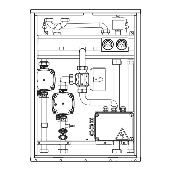
- Page 32 STRUTTURA STRUCTURE Termostato limite impianto bassa temperatura riarmo automatico High limit thermostat low temperature system automatic reset Termostato limite impianto bassa temperatura riarmo manuale High limit thermostat low temperature system manual reset Sonda impianto bassa temperatura Low temperature system NTC sensor Circolatore impianto bassa temperatura Low temperature system pump Circolatore impianto alta temperatura...
- Page 33 Rmix RD Mmix COLLEGAMENTI IDRAULICI HYDRAULIC CIRCUIT - Entrata (3/4”) - Inlet (3/4”) - Uscita (3/4”) - Outlet (3/4”) - Mandata impianto diretto (3/4”) - Delivery, direct system (3/4”) Mmix - Mandata impianto miscelato (1”) Mmix - Delivery, mixed system (1”) Rmix - Ritorno impianto miscelato (1”) Rmix - Return, mixed system (1”) - Ritorno impianto diretto (3/4”)
- Page 34 CONNECT AT/BT LE è equipaggiato di circolatori ad alta efficienza e controllo elettronico le cui prestazioni, da utilizzare per il dimensionamento degli impianti, sono riportate nel grafico. CONNECT AT/BT LE is equipped with high efficiency electronically controlled circulators whose performance, to be used to size the systems, are shown in the graph. CONNECT AT/BT LE est équipé...
- Page 35 Al primo avviamento e almeno ogni anno è utile controllare la rotazione dell’albero dei circolatori in quanto, soprattutto dopo lunghi periodi di non funzionamento, depositi e/o residui possono impedirne la libera rotazione. When starting up for the first time and at least once a year, it is advisable to check that the shaft of the circulator rotate. This is necessary because, especially after lengthy periods of inactivity, deposits and/or residue may stop it rotating freely.
- Page 36 Indoor boilers Caldaie da interno Chaudière pour installation à l’intérieur Kotły przeznaczone do montażu wewnątrz pomieszczenia...
- Page 37 Outdoor boilers Caldaie da esterno Chaudière pour installation à l’extérieur Kotły przeznaczone do montażu na zewnątrz...
- Page 38 TABT: Termostato ambiente bassa temperatura - NE: Nero - GR: Grigio - BI: TABT: Room thermostat low temperature system - NE: Black - GR: Grey - BI: Bianco - MR: Marrone - BL: Blu - G/V: Giallo/Verde - M2A: Morsetto 2 poli - F2: White - MR: Brown - BL: Blue - G/V: Yellow/Green - M2A: 2-pole terminal - F2: Fuse 2AF - MA: Auxiliary terminal board - RA: Anti-freeze resistance - FA: Phase - MC: Fusibile 2AF - MA: Morsettiera ausiliaria - RA: Resistenza antigelo - FA: Fase - MC:...
- Page 40 Tel. +39 0341 277111 Fax +39 0341 277263 info@berettaboilers.com www.berettaboilers.com In order to improve its products, Beretta reserves the right to modify the characteristics and information contained in this manual at any time and without prior notice. Consumers statutory rights are not aected.
Need help?
Do you have a question about the CONNECT AT LE and is the answer not in the manual?
Questions and answers