Cascade C Series User Manual
Weigh forks
Hide thumbs
Also See for C Series:
- Operator's pocket manual (2 pages) ,
- Installation instructions manual (10 pages)
Table of Contents
Advertisement
U
SER MANUAL
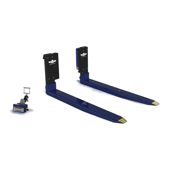
C-Series
Weigh Forks
NOTE: Weigh forks are factory calibrated
and ready to use.
Legal for trade models are factory
calibrated and ready to use. Additional
certification is required by a local weights
and measures authority.
IMPORTANT: The forks and indicator are
paired and calibrated as a set. Do not
separate. Consult Cascade Service
department with questions.
CAUTION: Treat this precise weighing
system with care. Environment and
application will affect the system and
its components. Conditions with mud,
grime, water, corrosive chemicals and
abrasive substances can damage or affect
performance of the weigh system.
Manual Number 8305557-R2
cascade
corporation
Cascade is a Registered Trademark of Cascade Corporation
Advertisement
Table of Contents


Need help?
Do you have a question about the C Series and is the answer not in the manual?
Questions and answers