Toyota UH9000S Fitting Instructions Manual
Land cruiser prado uhf cb transceiver
Hide thumbs
Also See for UH9000S:
- Fitting instructions manual (15 pages) ,
- Fitting instructions manual (14 pages)

Related Manuals for Toyota UH9000S


Summary of Contents for Toyota UH9000S
- Page 1 UHF CB Transceiver UH9000S / UH9060S / UH9080S Fitting Instructions Land Cruiser Prado Fitting Kit Part Number: UNIFK002...
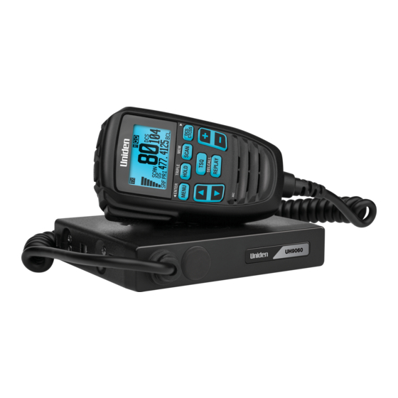
- Page 2 Fitting Instructions UH9000S / UH9060S / UH9080S UH9000S Speaker Microphone UHF CB Transceiver Front Rear Antenna Power Connector Lead Patch Accessory Harness Power Earth Fuse UH9060S / UH9080S Remote LCD Speaker Microphone UHF CB Transceiver Front Rear Extension Cable (Optional)
-
Page 3: Special Tools
Fitting Instructions UH9000S / UH9060S / UH9080S WARNING This vehicle is equipped with Supplemental Restraint System (SRS) airbags and seatbelt pretensioners. Before starting work, wait at least 90 seconds after the ignition switch is turned off and the negative (-) battery terminal cable is disconnected. - Page 4 Fitting Instructions UH9000S / UH9060S / UH9080S REMOVAL Removal - Engine Bay Open the bonnet. Remove the radiator shroud (13 scrivets). Push in the centre of the scrivets and pull up the shroud to remove. Take care to retain all scrivets.
- Page 5 Fitting Instructions UH9000S / UH9060S / UH9080S Cut the outer tang off the firewall grommet where indicated. Note: Refer to the Alternate antenna cable entry point on page 9 if both grommet entry points are being used.. Removal - Interior Using a taped flat blade screwdriver remove the front passenger’s side scuff plate (4 clips [ ], 10 claws and 2...
- Page 6 Fitting Instructions UH9000S / UH9060S / UH9080S Remove the passenger’s side front console box insert (2 clips [ ], 1 guide). Prise off carefully at retaining clip locations to avoid damaging the clips and insert. Remove the driver’s side front console box insert (2 clips [ ], 1 guide).
-
Page 7: Installation
Fitting Instructions UH9000S / UH9060S / UH9080S INSTALLATION Antenna Remove the sleeve, spacer washer, lock washer and nut from the antenna. Pass the antenna cable through the antenna mounting hole. Secure the antenna to the mount using the sleeve, spacer washer, lock washer and nut. - Page 8 Fitting Instructions UH9000S / UH9060S / UH9080S Follow the existing wiring harness passing the antenna cable through the (2) existing wiring harness clips. At the completion of the installation, cable tie the antenna harness to the existing wiring harness where indicated [ ].
- Page 9 Fitting Instructions UH9000S / UH9060S / UH9080S Alternate antenna cable entry point Remove the grommet from the firewall: Drill a 5 mm hole through the centre. b. Refit the grommet to the firewall opening. Pass a lead wire through the cut firewall grommet opening to the passenger’s side footwell.
- Page 10 14. Disconnect the lead wire and pull the antenna cable into the passenger’s side footwell. Power Lead Patch Harness - UH9000S Route the power lead patch harness from the driver’s side footwell, behind the bottom edge of the console box assembly to the rear power socket connector.
- Page 11 Fitting Instructions UH9000S / UH9060S / UH9080S Position the power lead patch harness fuse holder/s neatly behind the driver’s side instrument panel finish cushion and carpet. Cable tie [ ] using self-adhesive cable tie mounting blocks where necessary to avoid fouling and rattling.
- Page 12 Fitting Instructions UH9000S / UH9060S / UH9080S Disconnect the rear power socket connector and dehouse the (2) connector pins from the rear power socket connector [1]. House the (2) removed pins in the free patch harness connector [2]. House the (2) free patch harness pins into the original rear power socket connector [3].
- Page 13 Fitting Instructions UH9000S / UH9060S / UH9080S Slide the UHF CB transceiver into the cradle and connect the power lead. Fit the antenna adapter (supplied) to the antenna cable and connect to the UHF CB transceiver. UH9060S / UH9080S Fold back the insulation padding from the underside of the front passenger’s side instrument panel under cover sub-...
- Page 14 Fitting Instructions UH9000S / UH9060S / UH9080S Slide the UHF CB transceiver into the cradle and connect the power lead patch harness. Fit the antenna adapter (supplied) to the antenna cable and connect to the UHF CB transceiver. Connect the speaker microphone extension cable to the UHF CB transceiver and route behind the carpet line, behind the centre console to the driver’s side footwell.
- Page 15 Fitting Instructions UH9000S / UH9060S / UH9080S Speaker Microphone UH9000S Hang the speaker microphone on the hanger and connect the cable to the UHF CB transceiver. Ensure the speaker microphone cable routing does not interfere with any of the vehicle’s controls.
- Page 16 Fitting Instructions UH9000S / UH9060S / UH9080S COMPLETION IMPORTANT Ensure the interior wiring and any excess antenna cable is positioned to avoid fouling and rattling (cable tie as required at a minimum of every 200 mm. Use self-adhesive cable tie mounting blocks where necessary).
Need help?
Do you have a question about the UH9000S and is the answer not in the manual?
Questions and answers