Vertiv Liebert GXT5 Series Installer/User Manual
120 v input, 120 v output
Hide thumbs
Also See for Liebert GXT5 Series:
- User manual (118 pages) ,
- Installer/user manual (82 pages) ,
- Installer and user manual (82 pages)
Table of Contents
Advertisement
Advertisement
Table of Contents
Troubleshooting

Related Manuals for Vertiv Liebert GXT5 Series


Summary of Contents for Vertiv Liebert GXT5 Series
- Page 1 Liebert® GXT5™ UPS 120 V Input, 120 V Output Installer/User Guide...
- Page 2 Vertiv. This document is the property of Vertiv and contains confidential and proprietary information owned by Vertiv. Any copying, use or disclosure of it without the written permission of Vertiv is strictly prohibited. Names of companies and products are trademarks or registered trademarks of the respective companies.
-
Page 3: Table Of Contents
2�3� Installing the UPS ����������������������������������������������������������������������������������������������������������������������������������������������������������������������������������������������������������������������������������������������������12 2�3�1� Tower Installation ����������������������������������������������������������������������������������������������������������������������������������������������������������������������������������������������������� 12 2�3�2� Rack Installation ������������������������������������������������������������������������������������������������������������������������������������������������������������������������������������������������������� 13 2�4� Installing External Battery Cabinets ���������������������������������������������������������������������������������������������������������������������������������������������������������������������� 13 2�5� Connecting AC Input Power ������������������������������������������������������������������������������������������������������������������������������������������������������������������������������������������ 15 2�6� Communication Connections ����������������������������������������������������������������������������������������������������������������������������������������������������������������������������������������������������������16 Vertiv | Liebert® GXT5™ | Installer/User Guide... - Page 4 4�2�3� Status Screen ������������������������������������������������������������������������������������������������������������������������������������������������������������������������������������������������������������� 29 4�2�4� Settings Submenu �������������������������������������������������������������������������������������������������������������������������������������������������������������������������������������������������32 4�2�5� Control Screen ����������������������������������������������������������������������������������������������������������������������������������������������������������������������������������������������������������� 41 4�2�6� Log Screen ������������������������������������������������������������������������������������������������������������������������������������������������������������������������������������������������������������������� 42 4�2�7� About Screen ��������������������������������������������������������������������������������������������������������������������������������������������������������������������������������������������������������������45 4�3� Editing Display and Operation Settings �������������������������������������������������������������������������������������������������������������������������������������������������������������������������47 4�3�1� Settings Prompts ����������������������������������������������������������������������������������������������������������������������������������������������������������������������������������������������������� 47 Vertiv | Liebert® GXT5™ | Installer/User Guide...
- Page 5 6�2� Audible Alarm (Buzzer) ������������������������������������������������������������������������������������������������������������������������������������������������������������������������������������������������������������������ 63 6�2�1� Faults �����������������������������������������������������������������������������������������������������������������������������������������������������������������������������������������������������������������������������������64 6�3� Troubleshooting UPS Issues �������������������������������������������������������������������������������������������������������������������������������������������������������������������������������������65 Chapter 7: Specifications ��������������������������������������������������������������������������������������������������������������������������������������������������������������67 7�1� Battery Run Times �����������������������������������������������������������������������������������������������������������������������������������������������������������������������������������������������������������������70 Appendix I: Open Source Software Legal Notices �������������������������������������������������������������������������������������������� 73 Appendix II: Technical Support ����������������������������������������������������������������������������������������������������������������������������������������������75 Vertiv | Liebert® GXT5™ | Installer/User Guide...
-
Page 6: Important Safety Information
IMPORTANT! This manual contains important safety instructions that must be followed during the installation and maintenance of the UPS and batteries. Read this manual thoroughly and the safety and regulatory information, available at https://www.vertiv.com/ComplianceRegulatoryInfo, before attempting to install, connect to supply, or operate this UPS. - Page 7 This page is intentionally left blank� Important Safety Information...
-
Page 8: Chapter 1: Gxt5 Description
MODEL NUMBER NOMINAL POWER RATING @ 120 V INPUT GXT5-500LVRT2UXL 500 VA/500 W GXT5-750LVRT2UXL 750 VA/750 W GXT5-1000LVRT2UXL 1000 VA/1000 W GXT5-1500LVRT2UXL 1500 VA/1350 W GXT5-2000LVRT2UXL 2000 VA/1800 W GXT5-3000LVRT2UXL 3000 VA/2700 W Vertiv | Liebert® GXT5™ | Installer/User Guide... -
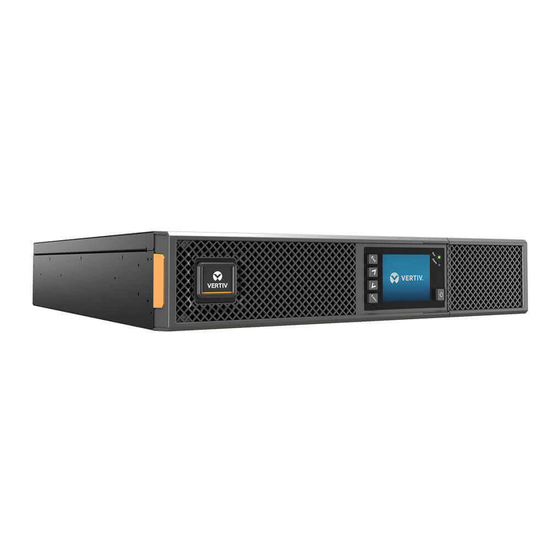
Page 9: 1�2� Front Panels
1.2. Front Panels The various GXT5 models have the same general appearance, with the main difference being the receptacle types on the rear panel� Figure 1-1 Front View 1.3. Rear Panels The following figures detail the rear-panel features for each GXT5 model� Figure 1-2 GXT5-500/750/1000/1500LVRT2UXL Rear Panel ITEM DESCRIPTION... - Page 10 External-battery connector Non-programmable output receptacles, NEMA 5-20R Programmable output receptacles, NEMA 5-20R Input circuit breaker Input-power plug and cable, NEMA L5-20P R232 port, RJ-45/RJ-11 connection Terminal-block communication connectors Output-power plug and cable, NEMA L5-20R Vertiv | Liebert® GXT5™ | Installer/User Guide...
- Page 11 Figure 1-4 GXT5-3000LVRT2UXL Rear Panel ITEM DESCRIPTION Liebert® IntelliSlot™ port USB port Un-used External-battery connector Non-programmable output receptacles, NEMA 5-20R Programmable output receptacles Output circuit breakers Input-power plug and cable, NEMA L5-30P R232 port, RJ-45/RJ-11 connection Terminal-block communication connectors Output-power plug and cable, NEMA L5-30R Input circuit breaker Cooling fan GXT5 Description...
-
Page 12: 1�4� Battery Cabinet
UPS operating principle� Table 1-2 on the next page, describes the function of the major components in the UPS� NOTE: Figure 1-6 on the next page, is one example of basic operation� Vertiv | Liebert® GXT5™ | Installer/User Guide... - Page 13 Figure 1-6 Basic Operating Principle Diagram Table 1-2 Major Components ITEM COMPONENT OPERATION/FUNCTION Transient Voltage Surge Provide surge protection� Filter electromagnetic interference (EMI) and radio frequency interference (RFI)� Minimize Suppression (TVSS) surges or interference present in the utility power and protect devices connected on the same branch as the UPS� and EMI/RFI Filters In normal operation, converts utility AC power to regulated DC power for use by the inverter while ensuring that Rectifier/Power Factor...
-
Page 14: 1� 6 � Ups States And Operating Modes
• Frequency Converter - 50 Hz – Bypass Disabled • Frequency Converter - 60Hz – Bypass Disabled NOTE: The default for all models of the Liebert® GXT5 is “Auto Sensing - 50 Hz or 60 Hz – Bypass Enabled.” Vertiv | Liebert® GXT5™ | Installer/User Guide... -
Page 15: 1�6�5� Eco Mode
1.6.5. ECO Mode The energy-saving ECO mode reduces power consumption by powering the load via bypass if the bypass voltage is normal or by powering the load via the inverter when the bypass voltage is abnormal� You can use ECO mode to power equipment that is not sensitive to power-grid quality to via bypass and reduce power consumption�... -
Page 16: Chapter 2: Installation
• Inspect the UPS for shipping damage� If any shipping damage is found, report it to the carrier and your local Vertiv representative immediately� • Check the accessories included against the packing list� If there is any discrepancy, contact your local Vertiv representative immediately�... -
Page 17: 2�3� Installing The Ups
2.3. Installing the UPS The UPS may be installed as a tower or in a rack, depending on available space and use considerations� Determine the type of installation and follow the appropriate instructions� See Tower Installation Rack Installation on next page�... -
Page 18: 2�3�2� Rack Installation
61. Take proper precautions when lifting them. To install the EBC(s): 1� Inspect the EBC for freight damage� Report damage to the carrier and your local dealer or Vertiv representative� 2� For tower installation: • An additional set of support-base extensions ships with each EBC�... - Page 19 5� Connect the supplied EBC cable(s) to the rear of the cabinet, then to the rear of the UPS, see Figure 2-2� 6� Turn the EBC breaker to the “On” position� 7� Verify the circuit breaker on the EBC is in the “On” position� The additional back-up run time is enabled�...
-
Page 20: 2�5� Connecting Ac Input Power
Do not overload any output receptacle. Output cable length should not exceed 10 m (32.8 ft). To connect equipment, plug equipment into the appropriate output receptacles on the rear of the UPS, see the appropriate figure for your model in Rear Panels page 4� Vertiv | Liebert® GXT5™ | Installer/User Guide... -
Page 21: 2�6� Communication Connections
2� Insert the card into the slot, and secure with the screws that held the cover plate� To make connections to the card, refer to the Installer/User Guide for the appropriate IntelliSlot card available at www�vertiv�com� 2.6.2. Connecting to the Dry-contact Port The UPS includes a dry-contact port�... - Page 22 When NC, Pins 11 and 12 are opened when the fault occurs� Output 6 11, 12 Remote Fault Alert 6 Options are: • Low battery • On battery • On bypass • UPS fault (default) Vertiv | Liebert® GXT5™ | Installer/User Guide...
-
Page 23: 2�6�3� Connecting A Remote Emergency Power-Off (Repo) Switch
2.6.3. Connecting a Remote Emergency Power-off (REPO) Switch The UPS includes an EPO connection in the dry-contact port� See the appropriate figure for your model in Rear Panels page 4, for the location of the port� UPS ships with a REPO jumper installed, allowing the UPS to operate as a normally-closed switch system (fail-safe)� Opening the circuit disables the UPS�... -
Page 24: 2�6�4� Connecting A Usb Cable
2.6.5. Connecting CLI Communication Cables The UPS supports the Vertiv command-line interface for operation with Vertiv ACS and other third-party monitoring protocols� The RJ-45 port (labeled “R232”) is used for CLI connection� See the appropriate figure for your model in... - Page 25 This page is intentionally left blank� Installation...
-
Page 26: Chapter 3: Operating The Ups
7� If this is the first-time start-up of the UPS, the Start-up Guidance wizard opens to set the basic parameters of the UPS� Follow the prompts� For detailed description of UPS display functions and settings, see Operation and Display Panel page 29� Vertiv | Liebert® GXT5™ | Installer/User Guide... -
Page 27: 3�3� Transferring To Battery Mode
3.3. Transferring to Battery Mode The UPS operates in Normal mode unless the mains/utility power fails or it is performing a battery self test, then it automatically transfers to Battery mode for the back-up time available or the mains/utility power is restored� Once input power is restored, the UPS returns to Normal mode�... -
Page 28: 3�6� Shutting-Down The Ups Completely
To manually power-off in an emergency, disconnect the terminal connecting the REPO port on the rear of the UPS� If mains/utility power is present, the UPS control circuit remains active even though output power is disabled� To remove all mains/utility power, disconnect the external main-input circuit breaker� Vertiv | Liebert® GXT5™ | Installer/User Guide... - Page 29 This page is intentionally left blank�...
-
Page 30: Chapter 4: Operation And Display Panel
Run indicator LED, see LED Indicators page 27� Alarm indicator LED, see LED Indicators page 27� Power button, see Table 4-1 on the next page� Menu keys, see Table 4-1 on the next page� LCD panel� Vertiv | Liebert® GXT5™ | Installer/User Guide... - Page 31 Table 4-1 Display-panel Button Functions and Descriptions BUTTON FUNCTION DESCRIPTION Enter Confirm or enter selection� Move to previous page, increase value, move left� Down Move to next page, decrease value, move right� Escape Go back� Power Power-on the UPS, power-off the UPS, transfer to Bypass Mode� NOTE: While the UPS is operating, the LCD will dim and display a screen saver if there is no active alarm or user interaction for two minutes, see Figure...
-
Page 32: 4�1� Led Indicators
Use the function keys to navigate through the menu, and view statuses or select settings in the screens� 4.2.1. Start-up and Flow Screens At start-up, the UPS executes a system test and displays the Vertiv logo screen for about 10 seconds, shown Figure 4-1 page 25�... -
Page 33: 4�2�2� Main Menu
About Product and network information, see About Screen page 45� Maintenance Service-only, service-password protected page for use only by Vertiv service representatives� Figure 4-4 Main Menu ITEM DESCRIPTION ECO-mode indicator Programmable-outlet indicator Ambient temperature and humidity� Only displays when sensors are connected�... -
Page 34: 4�2�3� Status Screen
Input Status Options L-N voltage (V) Line-neutral voltage of input power� L-N current (A) Line-neutral current of input power� Frequency (Hz) Frequency of input of input power� Power Factor Power factor of the input power� Vertiv | Liebert® GXT5™ | Installer/User Guide... - Page 35 Energy (kWh) Input power� Input black count The number times that the input voltage was lost or dropped below 60 VAC (black out)� Resets to 0 when UPS is powered down� Input brown count The number of times that the input voltage was too low to support the load and the UPS was forced to switch to battery power (brown out)�...
- Page 36 Output power� Load Status Options Sout (kVA) Apparent output power� Pout (kW) Active output power� Power Factor Power factor of output power� Load percent (%) Percentage of recent power rated to output power� Vertiv | Liebert® GXT5™ | Installer/User Guide...
-
Page 37: 4�2�4� Settings Submenu
4.2.4. Settings Submenu The settings screen consists of tabs that list UPS settings for configuration and adjusting parameters with tabs for: • Output • Battery • Monitor • System • Outlets NOTE: Do not change parameter settings or reset to factory defaults when powering-off the UPS. To modify UPS settings: 1�... - Page 38 (Option only available when Run mode is set to ECO�) Sets the percentage that the input voltage may be above or below the selected output voltage setting and remain in ECO mode� • ± 5% • ± 10% (default) • ± 15% Vertiv | Liebert® GXT5™ | Installer/User Guide...
- Page 39 EBCs automatically with Autotest� NOTE: Autotest is used for up to 6 Vertiv EBCs. If more than 6 Vertiv EBCs are connected, the number of cabinets must be set manually. For third-party external batteries, set this option to 0 and use External battery AH setting above.
- Page 40 NOTE The maximum setting of this value always shows as 13A on the display however it varies based on internal battery size and the number of EBCs connected. If the value does not save after it is selected, it is too high for the model. Vertiv | Liebert® GXT5™ | Installer/User Guide...
- Page 41 Temp compensation When enabled, the UPS will adjust the charging voltage of the batteries based on temperature in order to preserve battery life� It will increase the voltage if the UPS is operating in a cold environment� It will decrease the voltage if the UPS is operating in a warm environment�...
- Page 42 • Enable (with Auto restart disabled) = The UPS will start up and allow the user to turn on the output when power returns after the battery has been fully depleted • Disable = The UPS cannot start with a fully depleted battery (default) Vertiv | Liebert® GXT5™ | Installer/User Guide...
- Page 43 Remote control Allows the UPS to be controlled remotely via the CLI or RDU101 card� • Enable (default) • Disable Any mode shutdown auto restart enable Automatically restart the UPS after an “Any mode shutdown” signal is received� When the UPS is shut down via dry-contact inputs 1 or 2, it will restart automatically if this option is enabled�...
- Page 44 Power off time Sets the time of day to power off the UPS on the selected day� This option is only shown when sleep mode is enabled� • 00:00 - 23:59 (default 00:00) Vertiv | Liebert® GXT5™ | Installer/User Guide...
- Page 45 IT system compatibility When this option is enabled, the “Input phase reversed” and “Input ground lost” alarms are disabled� • Enable • Disable (default) Outlet Parameter Options Apply the same settings as outlet 1 Available on outlets 2 through 4, this applies the settings for Outlet1 to this outlet� This lets you apply the settings for Outlet1 and apply identical settings to any other programmable outlet�...
-
Page 46: 4�2�5� Control Screen
2� Use the arrow buttons to move the cursor to the option, then press Enter to select the control� Figure 4-6 Control Screen Control Options Turn on/off/to bypass Opens the dialog to change operating modes, see Operating the UPS page 25� Vertiv | Liebert® GXT5™ | Installer/User Guide... -
Page 47: 4�2�6� Log Screen
Mute/Unmute audible alarm Silences or un-silences the audible alarm, see Silencing the Audible Alarm page 25� Start/Stop battery manual test Starts the battery self test manually� If the manual self test is already running, stop the self test� Clear faults Clears displayed faults after the issue causing the fault is resolved, see Table 6-2 page... - Page 48 The inverter is off due to DC bus voltage out of acceptable range� The load will transfer to bypass if the bypass is available DC bus abnormal because the bus voltage is outside of the acceptable range� The discharger is faulty, because the bus voltage exceeds the range when the discharger starts� Contact Vertiv Technical DC/DC fault Support�...
- Page 49 A short has occurred on the output� Check the output cables and for any equipment that may have shorted� Output voltage The output voltage is outside the normal voltage range� The UPS will power off� Check output settings or contact Vertiv Technical abnormal Support�...
-
Page 50: 4�2�7� About Screen
Note: The tab shown in the figure is an example of the graph and does not represent the actual capacity values for your UPS model� Product Information Product Type UPS model number� Serial number UPS serial number� Vertiv | Liebert® GXT5™ | Installer/User Guide... - Page 51 Time since startup Elapsed time since start-up of the UPS� Boot FW version Version of MCU boot firmware on the monitor board� Monitor FW version Version of MCU application firmware on the monitor board� DSP FW version Version of DSP firmware on the UPS power-module� MAC address Shows the MAC address of the RDU101 card�...
-
Page 52: 4�3� Editing Display And Operation Settings
‘Turn on/Turn off/to Bypass’ on the LCD panel ‘Control’ page)� Cannot set this on line, please Appears when attempting to change the output phase number while the output is connected� unplug REPO Vertiv | Liebert® GXT5™ | Installer/User Guide... -
Page 53: 4�3�2� Changing The Password
4.3.2. Changing the Password The default password is 111111 (six ones)� You must use the current password to change the password� NOTE: We recommend that you change the password from the default to protect your system and equipment. Record the new password and store it in an accessible location for later retrieval. 1�... -
Page 54: 4�3�4� Setting The Date And Time
5� Use the up/down arrows to select the date/time, then press Enter to confirm� 6� Use the down arrow to select the digit to change and the up arrow to select the correct digit� Repeat as needed to set each digit� Vertiv | Liebert® GXT5™ | Installer/User Guide... - Page 55 This page is intentionally left blank�...
-
Page 56: Chapter 5: Maintenance
• Do not lay tools or metal parts on top of batteries� • Disconnect charging source prior to connecting or disconnecting battery terminals� • If the battery kit is damaged in any way or shows signs of leakage, contact your Vertiv representative immediately�... - Page 57 5� Compare the new and old battery pack to make sure they are the same type and model� If so, proceed with step 6� If they are different, stop and contact your Vertiv representative, or Technical Support, http://www� V ertiv�com/ en-us/support/�...
-
Page 58: 5�2� Charging Batteries
If the UPS will be stored for a long time, We recommend connecting the UPS to input power for at least 24 hours every 4 to 6 months to ensure full recharge of the batteries� Vertiv | Liebert® GXT5™ | Installer/User Guide... -
Page 59: 5�3� Checking Ups Operation
4� Check the flow screen to ensure the UPS is operating in Normal mode� If the UPS is operating in Bypass mode, contact Vertiv Technical Support� 5� Check the flow screen to see if batteries are discharging (operating in Battery mode) while utility power is normal� If so, contact Vertiv Technical Support� 5.4. Cleaning the UPS WARNING! Risk of electric shock Can cause injury or death. -
Page 60: 5�5�1� Updating Firmware With Rdu101 Card Connection
The name and password may have been changed from the default. NOTE: For detailed operating instructions for the card, refer to the Liebert® IntelliSlot™ RDU101 Communications Card Installer/User Guide, available at www.Vertiv.com. Updating MCU Firmware via RDU101 NOTE: Do not update firmware while the UPS is on Battery mode. - Page 61 c� Enter the Username and Password, then click Login� The factory-defaults: Username : Liebert (case-sensitive) Password: Liebert (case-sensitive) NOTE: The name and password may have been changed from the default. Be sure to obtain the username and password from an administrator. The status of the transfer displays in the File Transfer Status section�...
-
Page 62: 5�6� Updating Dsp Firmware Via Rdu101
3� On a computer connected to the same network as the RDU101, open a browser window and enter the IP address of the RDU101 card in the address bar� You can get the card’s IP address from the display panel� Select the About menu then the Product tab,and locate IPv4 address� Vertiv | Liebert® GXT5™ | Installer/User Guide... - Page 63 NOTE: We recommend using the Google Chrome browser. 4� Upload the update file using the card’s user interface, see Figure 5-5 below� a� Select the “GXT5” tab, then the File Transfer folder in the tab-menu pane on the left-hand side of the page� b�...
-
Page 64: 5�7� Updating Firmware With A Cli Connection
Figure 5-6 Firmware Version on the RDU101 User Interface 5.7. Updating Firmware with a CLI Connection You can use the Vertiv command-line interface to update firmware with a computer connected to the R232 (RJ- 45) port on the rear of the UPS�... - Page 65 • Select 115200 for the connection speed� • Open the emulator session� 4� On the CLI, enter the username and password: • Default username = user • Default password = 123456 5� On the command line, enter update, then press d on the keyboard, see Figure 5-7 on the next page 6�...
- Page 66 The status of the transfer displays in a status dialog� After about 2 minutes, the UPS restarts and the CLI exits update mode� NOTE: The transfer process takes about 2 minutes. Do not close the status dialog. a� You can check the firmware version by entering status system in the command line� Vertiv | Liebert® GXT5™ | Installer/User Guide...
- Page 67 Figure 5-9 File Transfer with the CLI Maintenance...
-
Page 68: Chapter 6: Troubleshooting
NOTE: When an alarm is indicated, an alarm message is logged. Table 4-4 page 42, describes the alarm messages you may see. When a fault is indicated, front-panel display list the fault, which are described in Table below. Vertiv | Liebert® GXT5™ | Installer/User Guide... -
Page 69: 6�2�1� Faults
6.2.1. Faults When the fault indicator is illuminated, the LCD displays the fault� The faults are described in Table 6-2 below� Table 6-2 Description of displayed faults DISPLAYED FAULT CAUSE CORRECTIVE STEPS Battery test fail The battery is bad or weak� Contact technical support�... -
Page 70: 6�3� Troubleshooting Ups Issues
Vertiv Technical Support� Visit the GXT5 product page at www�vertiv�com for contact information� When reporting a UPS issue to Vertiv, include the UPS model and serial number� These are located in several places for your ease of location: • On the top panel (rack mount orientation) •... - Page 71 This page is intentionally left blank� Troubleshooting...
-
Page 72: Chapter 7: Specifications
Audible Noise <46 dBA max� at 3 ft (1 m) front and sides, <43 dBA max� at 3 ft (1 m) rear Agency Surge Immunity IEEE/ANSI C62�41 Category B (6kV/3kA) Transportation ISTA Procedure 1A Vertiv | Liebert® GXT5™ | Installer/User Guide... - Page 73 Table 7-2 UPS Specifications, 1500 VA to 3000 VA models MODEL GXT5- 1500LVRT2UXL 2000LVRT2UXL 3000LVRT2UXL RATING 1500 VA/ 1350 W 2000 VA/ 1800 W 3000 VA/ 2700 W Dimensions, D×W×H, in. (mm) 21�3 x 16�9 x 3�4 Unit 18�5 x 16�9 x 3�4 (470 x 430 x 85) (540 x 430 x 85) 28�2 x 22�4 x 10�3 Shipping...
- Page 74 Storage Elevation 50,000 ft (15,0000 m) maximum Agency Safety UL1778 4th Edition and CSA 22�2 No� 107�1 RFI/EMI FCC Part 15 Class A Surge Immunity ANSI C62�41 Category B Transportation ISTA Procedure 1A Vertiv | Liebert® GXT5™ | Installer/User Guide...
-
Page 75: 7�1� Battery Run Times
7.1. Battery Run Times Table 7-4 Battery Run Time in Minutes, GXT5-500LVRT2UXL NUMBER OF EXTERNAL BATTERY CABINETS INTERNAL LOAD BATTERY ONLY 190�6 625�3 1105�6 1543�7 1820�7 1996�9 2118�9 2208�4 2276�8 2330�9 2374�6 103�5 338�1 593�7 854�4 1132 1392�2 1607�3 1765 1885�6 1980�8 2057�8... - Page 76 42�9 82�6 119�5 158�2 195�7 232�8 368�9 312�8 353�4 394�4 1350 1215 7�9 37�7 71�8 105�9 139�3 172�7 204�6 273�7 309�7 345�9 1500 1350 6�7 32�4 92�3 153�1 183�5 290�4 243�1 274�9 307�1 Vertiv | Liebert® GXT5™ | Installer/User Guide...
- Page 77 Table 7-8 Battery Run Time in Minutes, GXT5-2000LVRT2UXL NUMBER OF EXTERNAL BATTERY CABINETS INTERNAL LOAD BATTERY ONLY 74�7 246�8 434�2 622�5 822�1 1029�1 1236�3 1425�8 1586�3 1713 1815�6 37�6 139�1 237�9 345�2 456�6 567�7 675�6 792�9 912�2 1033�1 1155�6 23�4 166�3 311�5 388�1...
-
Page 78: Appendix I: Open Source Software Legal Notices
Appendix I: Open Source Software Legal Notices The GXT5 product links the FreeRTOS software with Vertiv Group Corporation’s proprietary modules that communicate with the FreeRTOS software solely through the FreeRTOS API interface� This use is an exception to the FOSS GPLv2 license� The user is free to redistribute the FreeRTOS software and/or modify it under the terms of the GNU General Public License as published by the Free Software Foundation�... - Page 79 This page is intentionally left blank�...
-
Page 80: Appendix Ii:technical Support
Toll +39 02 98250222 In the United States Technical support e: liebert�upstech@vertiv�com p: 1-800-222-5877 menu option 1 Monitoring support e: liebert�monitoring@vertiv�com p: 1-800-222-5877 menu option 2 Warranty support e: microups�warranty@vertiv�com p: 1-800-222-5877 menu option 3 Vertiv | Liebert® GXT5™ | Installer/User Guide... - Page 81 This page is intentionally left blank�...
- Page 82 © 2019 Vertiv Group Corp. All rights reserved. Vertiv™ and the Vertiv logo are trademarks or registered marks of Vertiv Group Corp. All other names and logos referred to are trade names, trademarks, or registered trademarks of their respective owners. While every precaution has been taken to ensure accuracy and completeness herein.
Need help?
Do you have a question about the Liebert GXT5 Series and is the answer not in the manual?
Questions and answers