Vertiv Liebert GXT5 Installer/User Manual
120/208 v input (l1, l2, n, g), 120/208 v output (mv)
Hide thumbs
Also See for Liebert GXT5:
- User manual (118 pages) ,
- Installer and user manual (82 pages) ,
- Installer/user manual (82 pages)

Related Manuals for Vertiv Liebert GXT5


Summary of Contents for Vertiv Liebert GXT5
- Page 1 Liebert® GXT5 UPS Installer/User Guide 120/208 V Input (L1, L2, N, G), 120/208 V Output (MV)
- Page 2 The products covered by this instruction manual are manufactured and/or sold by Vertiv. This document is the property of Vertiv and contains confidential and proprietary information owned by Vertiv. Any copying, use, or disclosure of it without the written permission of Vertiv is strictly prohibited.
-
Page 3: Table Of Contents
3.10 Communication Connection 3.10.1 Connecting Liebert® lntelliSlot™ Communication 3.10.2 Connecting to the Dry Contact Port 3.10.3 Connecting a Remote Emergency Power Off (REPO) Switch 3.10.4 Connecting a USB Cable 3.10.5 Connecting CLI Communication Cables Proprietary and Confidential ©2024 Vertiv Group Corp. - Page 4 7.1 Symptoms that Require Troubleshooting 7.2 Audible Alarm (Buzzer) 7.2.1 Faults 7.3 Troubleshooting UPS Issues 8 Specification 8.1 Battery Run Times Appendices Appendix A: Technical Support and Contacts Appendix B: Open Source Software Legal Notices Proprietary and Confidential ©2024 Vertiv Group Corp.
-
Page 5: Important Safety Instructions
IMPORTANT! This manual contains important safety instructions that must be followed during the installation and maintenance of the UPS and batteries. Read this manual thoroughly and the safety and regulatory information, available at https://www.vertiv.com/ComplianceRegulatoryInfo, before attempting to install, connect to supply, or operate this UPS. - Page 6 Do not open or destroy batteries. Escaping electrolyte can cause injury to the skin and eyes. It may be toxic. • Please replace fuses only with the same type and amperage in order to avoid fire hazards. • Do not dismantle the UPS system. Proprietary and Confidential ©2024 Vertiv Group Corp. 1 Important Safety Instructions...
-
Page 7: Product Description
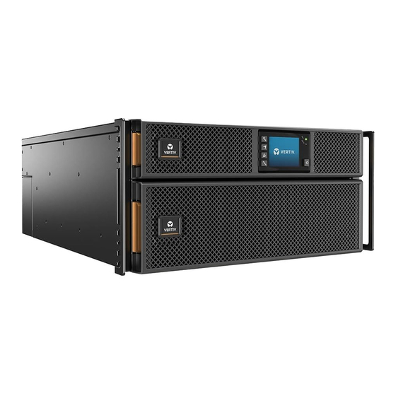
Vertiv™ Liebert® GXT5 UPS Installer/User Guide 2 Product Description The Vertiv™ Liebert® GXT5 is a compact, online uninterruptible power system (UPS) that continuously conditions and regulates its output voltage. The Liebert® GXT5 supplies computers and other sensitive equipment with clean sine-wave input power. -
Page 8: Rear Panels
Figure 2.2 GXT5-5000/6000MVRT4UXLN Rear Panel Item Description Vertiv™ Liebert® IntelliSlot™ port RS-232 port, RJ-45/RJ-11 connection—Used for CLI USB port RS-485 port, RJ-45 connection—Used for external temperature sensors External battery cabinet (EBC) connector Proprietary and Confidential ©2024 Vertiv Group Corp. 2 Product Description... - Page 9 RS-485 port, RJ-45 connection — Used for external temperature sensors Terminal-block communication connectors EBC connector Output breaker Maintenance bypass breaker Input breaker Knockouts for hard wired input and output Cover for power distribution box connector 2 Product Description Proprietary and Confidential ©2024 Vertiv Group Corp.
-
Page 10: Removable Power Distribution Box
NOTE: Output power capacity after derating with POD can be found under the About menu at the Efficiency tab. NOTE: In Figure 2.5 on the facing page, the components on PD5-001 are labeled. The features may be arranged differently on other PODs. Proprietary and Confidential ©2024 Vertiv Group Corp. 2 Product Description... - Page 11 4x L5-20R, 2x L6-30R PD5-006 L14-30P 4x L6-20R NOTE: In Figure 2.6 on the next page, the components on PD2-101 are labeled. The features are arranged differently on other PODs. 2 Product Description Proprietary and Confidential ©2024 Vertiv Group Corp.
- Page 12 PD2-103 4x L6-30R, 4x 5-15/20R T slot PD2-104 4x 5-15/20R T slot, 2x L6-30R, 2x L6-20R PD2-105 4x 5-15/20R T slot, 2x L5-30R, 2x L5-20R PD2-106 4x L6-20R, 4x L5-20R Proprietary and Confidential ©2024 Vertiv Group Corp. 2 Product Description...
- Page 13 4x L5-20R, 4x 5-15/20R T slot PD2-108 2x L6-30R, 2x L6-20R PD2-109 2x L14-30R PD2-200 4x IEC320-C19, 4x IEC320-C13 PD2-201 2x IEC320-C19, 8x IEC320-C13 PD2-202 12x IEC320-C13 PD2-204 2x IEC309-32A, 4x IEC320-C13 2 Product Description Proprietary and Confidential ©2024 Vertiv Group Corp.
-
Page 14: Internal Battery Packs
2.5 Internal Battery Packs The internal battery packs for all Vertiv™ Liebert® GXT5 MV models, shown in Figure 2.8 below, are located behind the access door on the front of the UPS. 5 kVA and 6 kVA units have 1 battery pack, and 8 kVA and 10 kVA units have 2 battery packs and 15 kVA and 20 kVA units have 4 battery packs. -
Page 15: Ups States And Operating Modes
The charger charges the battery in normal mode. On the front panel display, the run-indicator (green) is ON, the alarm indicator is OFF, and the buzzer is silent. Figure 2.10 on the next page shows the diagram of normal mode. 2 Product Description Proprietary and Confidential ©2024 Vertiv Group Corp. -
Page 16: Bypass Mode
NOTE: If utility power fails or if the utility voltage goes outside of the permissible range during bypass mode operation, the UPS shuts down and no output is supplied to the load. Proprietary and Confidential ©2024 Vertiv Group Corp. 2 Product Description... -
Page 17: Battery Mode
On the front panel display, the run indicator (green) is ON, the alarm indicator (yellow) is ON, and the buzzer beeps every two seconds. The LCD Flow screen displays On Battery. Figure 2.12 on the next page shows the diagram of battery mode. 2 Product Description Proprietary and Confidential ©2024 Vertiv Group Corp. -
Page 18: Frequency Converter Mode
NOTE: Powering off the UPS when it is in battery mode results in loss of output power to the connected load. 2.7.4 Frequency Converter Mode All models of the Vertiv™ Liebert® GXT5 are capable of frequency conversion. Frequency Conversion Mode can be selected using the configuration program. Allowable frequency operating mode include: •... -
Page 19: Eco Mode
UPS will transfer to Normal Mode. However, if a notification showing bypass failure or abnormal bypass voltage appears when the output is overloaded, the UPS will shut down the bypass and therefore the load will shut down. 2 Product Description Proprietary and Confidential ©2024 Vertiv Group Corp. - Page 20 Vertiv™ Liebert® GXT5 UPS Installer/User Guide This page intentionally left blank Proprietary and Confidential ©2024 Vertiv Group Corp. 2 Product Description...
-
Page 21: Installation
Inspect the UPS for shipping damage. If any shipping damage is found, report it to the carrier and your local Vertiv representative immediately. • Check the accessories included against the packing list. If there is any discrepancy, contact your local Vertiv representative immediately. CAUTION: The UPS is heavy (see Specification page 65, for the weight). -
Page 22: Tower Installation
2. If optional external battery cabinets will be connected, take out the spacers shipped with the battery cabinet. 3. Connect the spacers and the support bases as shown in Figure 3.1 above. Each Vertiv™ Liebert® GXT5 requires 2 support bases, one in the front and one in the rear. -
Page 23: Installing External Battery Cabinets
Take proper precautions when lifting them. To install the EBCs: Inspect the EBC for freight damage. Report damage to the carrier and your local dealer or Vertiv representative. 2. For tower installation: • An additional set of support-base extensions ships with each EBC. - Page 24 • Refer to the instructions included with the rack-mount kit to install. NOTE: Optional slide rails and securing hardware are sold separately. Please contact your Vertiv representative for options and Vertiv Technical Support for assistance. 4. Verify that the EBC breaker is in the Off position.
-
Page 25: Installing The Power Output Distribution Box
3.6 Installing the Power Output Distribution Box • PD5-UL6HDWR-MBS, PD5-001, PD5-002, PD5-003, PD5-004, PD5-005 and PD5-006 models fit the GXT5- 5000MVRT4UXLN and GXT5-6000MVRT4UXLN models of the Vertiv™ Liebert® GXT5. • PD5-UL10HDWR-MBS, PD2-101, PD2-102, PD2-103, PD2-104, PD2-105, PD2-106, PD2-107, PD2-108, PD2-109, PD2-200, PD2-201, PD2-202, PD2-204 models fit the GXT5-8000MVRT6UXLN, GXT5-10KMVRT6UXLN, GXT5- 15KMVRT11UXLN, and GXT5-20KMVRT11UXLN models of the Liebert®... -
Page 26: Installing The Power Distribution Box On Gxt5-8000Mvrt6Uxln And Gxt5- 10Kmvrt6Uxln Models
6. On the rear panel of the new UPS, remove the new power distribution box from the UPS. 7. Mount and connect the new UPS to the old power distribution box. Proprietary and Confidential ©2024 Vertiv Group Corp. 3 Installation... -
Page 27: Removing The Power Distribution Box From Gxt5- 8000Mvrt6Uxln And Gxt5-10Kmvrt6Uxln Models
3. Support the power distribution box and remove the two screws at the top of the box. 4. When removing the power distribution box, carefully pull apart the power distribution box connector and the UPS connector. 5. Replace power distribution box cover and restart the UPS. 3 Installation Proprietary and Confidential ©2024 Vertiv Group Corp. -
Page 28: Hardwired Input/Output Connections
National Electric Code/NFPA 70 requirements. Models/POD options subject to this requirement are: GXT5-5000MVRT4UXLN and GXT5- 6000MVRT4UXLN with POD PD5-001, PD5-002, PD5-003, PD5-004, PD5-005, or PD5-006. Proprietary and Confidential ©2024 Vertiv Group Corp. 3 Installation... -
Page 29: Branch Circuit Breaker
Recommended External Overcurrent Protection When Using Optional PD5 PODs GXT5-5000MVRT4UXLN GXT5-6000MVRT4UXLN GXT5-8000MVRT6UXLN GXT5-10KMVRT6UXLN GXT5-15KMVRT11UXLN 125A GXT5-20KMVRT11UXLN 125A Figure 3.7 Circuit Breakers Diagram Item Description 5 kVA and 6 kVA models 8 kVA through 20 kVA models Mains/Utility 3 Installation Proprietary and Confidential ©2024 Vertiv Group Corp. -
Page 30: Terminal Block Connections
POD attached to the rear of the unit. On 15 kVA and 20 kVA models, the knockouts are located directly on the rear of the unit. See Removable Power Distribution Box on page 6, for the location of the input/output knockouts on your Vertiv™ Liebert® GXT5 model. Table 3.2 below, details the electrical connection specifications. -
Page 31: Communication Connection
The I/0 dry contact port capacity is 125 VAC, 0.5 A; 30 VDC, 1 A. Figure 3.9 Dry Contact Port and Pin Layout NOTE: Pins 7 and 8 are shorted before delivery. 3 Installation Proprietary and Confidential ©2024 Vertiv Group Corp. - Page 32 Automatically detects number of external battery cabinets when pins 5 and 6 are connected to 5, 6 Detection Detection the detection port, see Installing External Battery Cabinets page 19. REPO REPO Input REPO power supply, 5 VDC 100 mA. Proprietary and Confidential ©2024 Vertiv Group Corp. 3 Installation...
-
Page 33: Connecting A Remote Emergency Power Off (Repo) Switch
2. Insert the stripped end into the plug terminals 1 and 2 respectively, then press down the terminals. Make sure that the cables are secure in the plug to prevent failure because of loose contact. 3 Installation Proprietary and Confidential ©2024 Vertiv Group Corp. -
Page 34: Connecting A Usb Cable
3.10.5 Connecting CLI Communication Cables The UPS supports the Vertiv command-line interface for operation with Vertiv ACS and other third party monitoring protocols. The RJ-45 port (labeled R232) is used for CLI connection. See the appropriate figure for your model in Rear Panels on page 4, for the location of the port. - Page 35 Vertiv™ Liebert® GXT5 UPS Installer/User Guide Item Description RXD (in) 3 Installation Proprietary and Confidential ©2024 Vertiv Group Corp.
- Page 36 Vertiv™ Liebert® GXT5 UPS Installer/User Guide This page intentionally left blank Proprietary and Confidential ©2024 Vertiv Group Corp. 3 Installation...
-
Page 37: Operating The Ups
Battery mode for the back-up time available or the mains/utility power is restored. Once input power is restored, the UPS returns to Normal mode. NOTE: Battery back-up run times are listed in Battery Run Times page 69. 4 Operating the UPS Proprietary and Confidential ©2024 Vertiv Group Corp. -
Page 38: Transferring From Normal To Bypass Mode
To manually power off in an emergency, disconnect the terminal connecting the REPO port on the rear of the UPS. If mains/utility power is present, the UPS control circuit remains active even though output power is disabled. To remove all mains/utility power, disconnect the external main-input circuit breaker. Proprietary and Confidential ©2024 Vertiv Group Corp. 4 Operating the UPS... -
Page 39: Operation And Display Panel
Move to previous page, increase value, move left. Down Move to next page, decrease value, move right. Escape Go back. Power Power on the UPS, power off the UPS, transfer to bypass mode. 5 Operation and Display Panel Proprietary and Confidential ©2024 Vertiv Group Corp. -
Page 40: Led Indicators
5.2.1 Start-up and Flow Screens At start-up, the UPS executes a system test and displays the Vertiv logo screen for about 10 seconds, shown in Figure 5.1 on the previous page. After the test completes, an overview screen shows status information, the active (green) power path, and the non-working power path (gray). -
Page 41: Main Menu
About Product and network information, see About Screen page 52. Maintenance Service only, service password protected page for use only by Vertiv service representatives. Figure 5.4 Main Menu 5 Operation and Display Panel Proprietary and Confidential ©2024 Vertiv Group Corp. -
Page 42: Status Screen
Line-neutral voltage of input power. L-N current (A) Line-neutral current of input power. Frequency (Hz) Frequency of input of input power. L-L voltage(V) Line-line voltage of input power. Proprietary and Confidential ©2024 Vertiv Group Corp. 5 Operation and Display Panel... - Page 43 Remaining capacity (%) Percent of capacity remaining for battery. Discharge count Number of discharges for the battery module. Total discharge time (Min) Number of minutes until battery is fully discharged. 5 Operation and Display Panel Proprietary and Confidential ©2024 Vertiv Group Corp.
- Page 44 Line-line voltage of output power. Energy (kWh) Output power Load Status Options Sout (kVA) Apparent output power. Pout (kW) Active output power. Power Factor Power factor of output power. Proprietary and Confidential ©2024 Vertiv Group Corp. 5 Operation and Display Panel...
-
Page 45: Settings Submenu
Startup on bypass Allows the UPS to start-up in bypass mode. • Enable — Start the UPS in bypass mode • Disable — Start the UPS in normal mode. (default) 5 Operation and Display Panel Proprietary and Confidential ©2024 Vertiv Group Corp. - Page 46 (Option only available when Run mode is set to ECO). Sets the amount that the input frequency (Hz) may be above or below the selected frequency setting and remain in ECO mode. • ±1 Hz • ±2 Hz • ±3 Hz (default) Proprietary and Confidential ©2024 Vertiv Group Corp. 5 Operation and Display Panel...
- Page 47 Sets the length of time after the batteries are replaced to generate an alarm to remind the user to replace the batteries. • Disable (default) • 1 - 72 months 5 Operation and Display Panel Proprietary and Confidential ©2024 Vertiv Group Corp.
- Page 48 If enabled, the UPS will beep when an alarm is generated. If disabled, it will be silent. See Audible Alarm (Buzzer) on page 63. • Enable (default) • Disable Proprietary and Confidential ©2024 Vertiv Group Corp. 5 Operation and Display Panel...
- Page 49 Automatically restart the UPS after an Any mode shutdown signal is received. When the UPS is shut down via dry contact inputs 1 or 2, it will restart automatically if this option is enabled. • Enable • Disable (default) 5 Operation and Display Panel Proprietary and Confidential ©2024 Vertiv Group Corp.
- Page 50 Battery mode shutdown — If the UPS is running on batteries and this input is triggered, the UPS shuts down • Any mode shutdown — If this input is triggered, the UPS shuts down regardless of current operating mode Proprietary and Confidential ©2024 Vertiv Group Corp. 5 Operation and Display Panel...
-
Page 51: Control Screen
To adjust the UPS controls: At the main menu, select the Control icon, and press Enter. 2. Use the arrow buttons to move the cursor to the option, then press Enter. 5 Operation and Display Panel Proprietary and Confidential ©2024 Vertiv Group Corp. -
Page 52: Log Screen
At the main menu, select the Log icon, and press Enter. 2. Use the arrow buttons to move the cursor left/right and select a tab, then press Enter to display the log for the selected tab. Proprietary and Confidential ©2024 Vertiv Group Corp. 5 Operation and Display Panel... - Page 53 UPS internal auxiliary power voltage fault. Contact Vertiv Technical Support. Battery cabinet More than 6 external battery cabinets are connected to the UPS with the auto-detect feature in use. Contact Vertiv service if using connect abnormal more than 6 EBCs.
- Page 54 DC/DC fault The discharger is faulty, because the bus voltage exceeds the range when the discharger starts. Contact Vertiv Technical Support. EOD turn off The inverter is off due to EOD. Check the mains power off state and recover the mains in time.
- Page 55 Rectifier fault The rectifier is off because the bus voltage is out of the acceptable range when the rectifier starts. Contact Vertiv Technical Support. The output power is larger than the rectifier overload point. Check that the input voltage meets the output load, if the mains input Rectifier overload falls to 176 V - 100 V, the load is derated linearly from 100% - 50%.
-
Page 56: About Screen
2. Use the arrow buttons to move the cursor left/right and select a tab, then press Enter to display the information for the selected tab. Figure 5.8 About Screen Tabs Proprietary and Confidential ©2024 Vertiv Group Corp. 5 Operation and Display Panel... - Page 57 Shows the gateway address of the RDU101 card. This is only shown when the RDU101 card is installed. Efficiency Tab Capacity This shows the maximum capacity of your UPS model. 5 Operation and Display Panel Proprietary and Confidential ©2024 Vertiv Group Corp.
-
Page 58: Editing Display And Operation Settings
While using the operation and display panel, prompts display to alert you to specific conditions or require confirmation of commands or settings. Table 5.5 on the facing page lists the prompts and their meaning. Proprietary and Confidential ©2024 Vertiv Group Corp. 5 Operation and Display Panel... -
Page 59: Changing The Password
6. A confirmation dialog opens to indicate a successful password change. 7. Press ESC to return to the settings or main men. Figure 5.10 New and Confirm Password Dialogs 5 Operation and Display Panel Proprietary and Confidential ©2024 Vertiv Group Corp. -
Page 60: Selecting The Display Language
5. Use the up/down arrows to select the date/time, then press Enter to confirm. 6. Use the down arrow to select the digit to change and the up arrow to select the correct digit. Repeat as needed to set each digit. Proprietary and Confidential ©2024 Vertiv Group Corp. 5 Operation and Display Panel... -
Page 61: Maintenance
• Disconnect charging source prior to connecting or disconnecting battery terminals. • If the battery kit is damaged in any way or shows signs of leakage, contact your Vertiv representative immediately. • Handle, transport, and recycle batteries in accordance with local regulations. - Page 62 5. Compare the new and old battery pack to make sure they are the same type and model. If so, proceed with step 6. If they are different, stop and contact your Vertiv representative, or Technical Support, http://www.Vertiv.com/ en-us/support/.
-
Page 63: Charging Batteries
4. Select the Setting menu, and look at the log for alarm and fault history. 5. Check the operating mode for Normal mode. If the UPS is operating in bypass mode, contact Vertiv Technical Support. 6. Check to see if batteries are discharging (operating in Battery mode) and utility power is normal. If so, contact Vertiv Technical Support. -
Page 64: Replacing The Ups Using Maintenance Bypass
NOTE: Secure only one captive screw on the maintenance bypass breaker cover; do not attempt to force the second screw. Figure 6.2 Maintenance Bypass Breaker Cover and Captive Screws Item Description Captive screws for POD Maintenance bypass breaker Proprietary and Confidential ©2024 Vertiv Group Corp. 6 Maintenance... -
Page 65: Firmware Updates
Use the Up/Down arrows to select YES, then press Enter. 6.6 Firmware Updates Firmware updates are available via the Vertiv website. Firmware update instructions are provided with the firmware download. 6 Maintenance Proprietary and Confidential ©2024 Vertiv Group Corp. - Page 66 Vertiv™ Liebert® GXT5 UPS Installer/User Guide This page intentionally left blank Proprietary and Confidential ©2024 Vertiv Group Corp. 6 Maintenance...
-
Page 67: Troubleshooting
Table 7.2 on the next page. 7.2.1 Faults When the fault indicator is illuminated, the LCD displays the fault. The faults are described in Table 7.2 on the next page. Figure 7.1 LCD Display—Fault Indicator 7 Troubleshooting Proprietary and Confidential ©2024 Vertiv Group Corp. -
Page 68: Troubleshooting Ups Issues
Vertiv Technical Support. Visit the Vertiv™ Liebert® GXT5 product page at www.vertiv.com for contact information. When reporting a UPS issue to Vertiv, include the UPS model and serial number. These are located in several places for your ease of location: •... -
Page 69: Specification
Hard-wired terminal terminal block 3W+G (L1-L2-N-G) connection L1-N, L2-N, Maximum 150 VAC Allowable Output AC Factory- 120/208 VAC at 120 degrees default VAC L1-L2 Factory- default 120 degrees Output Phase Angle 8 Specification Proprietary and Confidential ©2024 Vertiv Group Corp. - Page 70 32 to 122 (0 to 50) output derated by 1% per 1 °C above 40°C (derated), °F (°C) Storage Temperature, 5 to 122 (–15 to 50) °F (°C) Relative 0 – 95% non-condensing Humidity Proprietary and Confidential ©2024 Vertiv Group Corp. 8 Specification...
- Page 71 (1) L14-30P on a 10.5 ft (3.2 m) cord (1) connection (L-L-N-G) 5-20R Output power Hard-wired terminal block 3W + G 5-20R 5-20R L5-20R L5-20R L5-20R connection (L-L-N-G) L14-30R L6-20R L6-20R L6-30R L5-30R L6-30R L6-20R L6-30R 8 Specification Proprietary and Confidential ©2024 Vertiv Group Corp.
- Page 72 2 pole 60 A input breaker Custom Connector Input power connection 3W+G (L1-L2-N-G) to UPS (4) IEC320-C19 (2) IEC320-C19 (2) IEC309-32A Output power connection (12) IEC320-C13 (4) IEC320-C13 (8) IEC320-C13 (4) IEC320-C13 Proprietary and Confidential ©2024 Vertiv Group Corp. 8 Specification...
-
Page 73: Battery Run Times
776.0 892.5 1009.0 1125.0 1241.5 1000 1000 41.5 94.0 149.0 211.0 273.5 335.5 397.5 460.0 522.0 584.5 646.5 1500 1500 24.5 61.0 97.0 133.0 175.0 218.0 260.5 303.0 345.5 388.0 430.5 8 Specification Proprietary and Confidential ©2024 Vertiv Group Corp. - Page 74 1335.5 1488 1640.5 1600 1600 56.5 124.5 443.5 523.5 603.5 2400 2400 81.5 181.5 236.5 400.5 455.5 3200 3200 23.5 93.5 128.5 210.5 251.5 334.5 375.5 4000 4000 161.5 294.5 327.5 Proprietary and Confidential ©2024 Vertiv Group Corp. 8 Specification...
- Page 75 274.5 319.0 363.5 408.0 453.0 7500 7500 19.0 49.5 79.5 110.0 141.5 177.0 213.0 249.0 284.5 320.5 356.0 9000 9000 15.0 39.5 65.0 90.0 115.5 142.0 172.0 202.0 232.0 262.0 291.5 8 Specification Proprietary and Confidential ©2024 Vertiv Group Corp.
- Page 76 61.0 75.5 89.5 104.0 118.5 133.0 150.0 18000 18000 15.0 27.0 40.0 53.0 66.0 78.5 91.5 104.0 117.0 130.0 20000 20000 13.0 23.0 34.5 46.5 58.0 69.5 81.0 92.5 104.5 116.0 Proprietary and Confidential ©2024 Vertiv Group Corp. 8 Specification...
-
Page 77: Appendices
505 N Cleveland Ave Westerville, OH 43082 Europe Via Leonardo Da Vinci 8 Zona Industriale Tognana 35028 Piove Di Sacco (PD) Italy Asia 7/F, Dah Sing Financial Centre 3108 Gloucester Road, Wanchai Hong Kong Appendices Proprietary and Confidential ©2024 Vertiv Group Corp. - Page 78 Vertiv™ Liebert® GXT5 UPS Installer/User Guide This page intentionally left blank Proprietary and Confidential ©2024 Vertiv Group Corp. Appendices...
-
Page 79: Appendix B: Open Source Software Legal Notices
For a period of three (3) years after purchasing the Liebert® GXT5 product, the purchaser has the right to obtain a copy of the FreeRTOS software that is incorporated in the Liebert® GXT5 product. The purchaser can contact Vertiv Technical Support and request the software. - Page 80 Vertiv™ Liebert® GXT5 UPS Installer/User Guide This page intentionally left blank Proprietary and Confidential ©2024 Vertiv Group Corp.
- Page 81 Vertiv™ Liebert® GXT5 UPS Installer/User Guide...
- Page 82 Vertiv.com | Vertiv Headquarters, 505 N Cleveland Ave, Westerville, OH 43082 USA ©2024 Vertiv Group Corp. All rights reserved. Vertiv™ and the Vertiv logo are trademarks or registered trademarks of Vertiv Group Corp. All other names and logos referred to are trade names, trademarks or registered trademarks of their respective owners. While every precaution has been taken to ensure accuracy and completeness here, Vertiv Group Corp.
Need help?
Do you have a question about the Liebert GXT5 and is the answer not in the manual?
Questions and answers