Vertiv Liebert GXT5 User Manual
Hide thumbs
Also See for Liebert GXT5:
- Installer and user manual (82 pages) ,
- Installer/user manual (82 pages) ,
- Quick installation manual (56 pages)
Table of Contents
Advertisement
Quick Links
Advertisement
Table of Contents
Troubleshooting

Related Manuals for Vertiv Liebert GXT5


Summary of Contents for Vertiv Liebert GXT5
- Page 1 Liebert® GXT5 UPS Installer/User Guide 230 V Input, 230 V Output (I)
- Page 2 The products covered by this instruction manual are manufactured and/or sold by Vertiv. This document is the property of Vertiv and contains confidential and proprietary information owned by Vertiv. Any copying, use, or disclosure of it without the written permission of Vertiv is strictly prohibited.
-
Page 3: Table Of Contents
3.7.2 Connecting to the Dry contact Port 3.7.3 Connecting a Remote Emergency Power Off (REPO) Switch 3.7.4 Connecting a USB Cable 3.7.5 Connecting CLI Communication Cables 3.8 Installing a Parallel System 3.8.1 First Time Start-up of a Parallel System Proprietary and Confidential ©2024 Vertiv Group Corp. - Page 4 6.5 Replacing the UPS from the Power Distribution Box 6.6 Firmware Updates 7 Troubleshooting 7.1 Symptoms that Require Troubleshooting 7.2 Audible Alarm (Buzzer) 7.2.1 Faults 7.3 Troubleshooting UPS Issues 8 Specifications 8.1 Battery Run Times Proprietary and Confidential ©2024 Vertiv Group Corp.
- Page 5 Vertiv™ Liebert® GXT5 UPS Installer/User Guide Appendices Appendix A: Technical Support and Contacts Appendix B: Open Source Software Legal Notices Proprietary and Confidential ©2024 Vertiv Group Corp.
- Page 6 Vertiv™ Liebert® GXT5 UPS Installer/User Guide This page intentionally left blank Proprietary and Confidential ©2024 Vertiv Group Corp.
-
Page 7: Important Safety Instructions
IMPORTANT! This manual contains important safety instructions that must be followed during the installation and maintenance of the UPS and batteries. Read this manual thoroughly and the safety and regulatory information, available at https://www.vertiv.com/ComplianceRegulatoryInfo, before attempting to install, connect to supply, or operate this UPS. - Page 8 189.2 A (Duration: 155.3 ms) 1000IRT2UXL 13.21 A 9.375 A (Duration: 153.00 ms) 2000IRT2UXL 27.54 A 20.48 A (Duration: 172.48 ms) 3000IRT2UXL 39.92 A 28.6 A (Duration: 134.0 ms) Proprietary and Confidential ©2024 Vertiv Group Corp. 1 Important Safety Instructions...
-
Page 9: Product Description
Vertiv™ Liebert® GXT5 UPS Installer/User Guide 2 Product Description The Vertiv™ Liebert® GXT5 is a compact, online uninterruptible power system (UPS) that continuously conditions and regulates its output voltage. The Liebert® GXT5 supplies computers and other sensitive equipment with clean sine-wave input power. -
Page 10: Front Panels
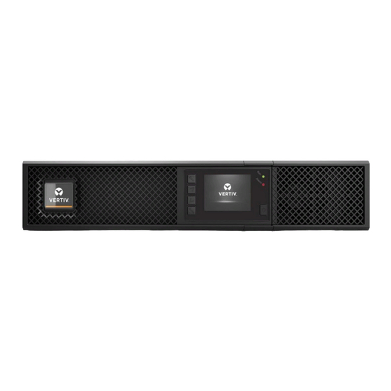
2.2 Front Panels The various Vertiv™ Liebert® GXT5 models have the same general appearance, with the main difference being the receptacle types on the rear panel. Figure 2.1 below, shows the 5 kVA to 10 kVA model in a tower and a rack configuration. When mounted in a rack, all units are turned 90 degrees. -
Page 11: Rear Panels
Description Operation/Display panel Upper bezel Lower bezel/battery access door 2.3 Rear Panels The following figures detail the rear panel features for each Vertiv™ Liebert® GXT5 model. Figure 2.2 GXT5-750/1000IRT2UXL (XLE) Rear Panel Item Description Vertiv™ Liebert® IntelliSlot™ port Ventilation hole... - Page 12 Programmable output receptacles Input-power plug and cable Dry contacts, Battery Detection (3), REPO input (REPO) RS-232 port – Used for CLI RS-485 port – Used for external temperature sensors USB port Proprietary and Confidential ©2024 Vertiv Group Corp. 2 Product Description...
- Page 13 C14 input-power plug and cable Terminal- block/Dry contact communication connectors RS-232 port - RJ-45/RJ-11 connection used for command line interface RS-485 port - RJ-45 connection used for external temperature sensors USB port 2 Product Description Proprietary and Confidential ©2024 Vertiv Group Corp.
- Page 14 Programmable output receptacles Input-power plug and cable Dry contacts, Battery Detection (3), REPO input (REPO) RS-232 port – Used for CLI RS-485 port – Used for external temperature sensors USB port Proprietary and Confidential ©2024 Vertiv Group Corp. 2 Product Description...
- Page 15 Input circuit-breaker reset button, 16 A Terminal-block/Dry contact communication connectors RS-232 port - RJ-45/RJ-11 connection used for command line interface RS-485 port - RJ-45 connection used for external temperature sensors USB port 2 Product Description Proprietary and Confidential ©2024 Vertiv Group Corp.
- Page 16 Programmable output receptacles Input-power plug and cable Dry contacts, Battery Detection (3), REPO input (REPO) RS-232 port – Used for CLI RS-485 port – Used for external temperature sensors USB port Proprietary and Confidential ©2024 Vertiv Group Corp. 2 Product Description...
- Page 17 Input circuit-breaker reset button, 20 A Terminal-block/Dry contact communication connectors RS-232 port - RJ-45/RJ-11 connection used for command line interface RS-485 port - RJ-45 connection used for external temperature sensors USB port 2 Product Description Proprietary and Confidential ©2024 Vertiv Group Corp.
- Page 18 Dry contacts, Battery Detection (3), REPO input (REPO) RS-232 port – Used for CLI RS-485 port – Used for external temperature sensors USB port Output circuit breakers Output-power plug and cable Proprietary and Confidential ©2024 Vertiv Group Corp. 2 Product Description...
- Page 19 Programmable output circuit breaker, 10 A (x2) Output circuit breaker - Controls terminal block output and non-programmable output receptacles Maintenance bypass breaker (MBB) Removable junction box with cable entry for hard-wire I/O Input circuit breaker 2 Product Description Proprietary and Confidential ©2024 Vertiv Group Corp.
- Page 20 Programmable C13 output receptacles Programmable output breakers Output circuit breaker - Controls terminal block output and non-programmable output receptacles Removable junction box with cable entry for hard-wire I/O Input circuit breaker Proprietary and Confidential ©2024 Vertiv Group Corp. 2 Product Description...
- Page 21 Installing a Parallel System on page 46 Input circuit breaker Bypass circuit breaker Knock-out /cable-entry for hard-wire I/O Output circuit breaker POD breaker Cover for optional POD - installation location EBC connector 2 Product Description Proprietary and Confidential ©2024 Vertiv Group Corp.
-
Page 22: Removable Power Distribution Box
Item Part Number Output Connections PD2-107 4x L5-20R, 4x 5-15/20R T slot PD2-200 4x IEC320-C19, 4x IEC320-C13 PD2-201 2x IEC320-C19, 8x IEC320-C13 PD2-202 12x IEC320-C13 PD2-204 2x IEC309-32A, 4x IEC320-C13 Proprietary and Confidential ©2024 Vertiv Group Corp. 2 Product Description... - Page 23 "(4) L6-20R Ouput Power "(2) L14- (2) L6-30R (2) L6-30R (4) L6-30R" (4) 5-15 /20R (2) L6-30R" Connection 30R" (4) 5-20R" (4) 5-20R" (8) 5-20R" " (2) L6-20R" (2) L6-20R" 2 Product Description Proprietary and Confidential ©2024 Vertiv Group Corp.
- Page 24 Ouput Power Connection (12) IEC320-C13 (4) IEC320-C13" (8) IEC320-C13" (4) IEC320-C13" Figure 2.15 PD5-CE10HDWRMBS for GXT5-8000/10KIRT5UXLN (XLE) Item Description POD Panel view (on rear of unit) POD inner surface view Quick connect Proprietary and Confidential ©2024 Vertiv Group Corp. 2 Product Description...
-
Page 25: Internal Battery Packs
2.5 Internal Battery Packs An example of the Vertiv™ Liebert® GXT5 internal battery packs is shown in Figure 2.16 below. They are located behind the access door on the front of the UPS. 3 kVA and below units have 1 battery pack, 5 kVA and 10 kVA units have 2 battery packs, and 16 kVA to 20 kVA units have 4 battery packs. -
Page 26: Major Internal Components And Operating Principle
Extracting this sine-wave input current ensures efficient use of utility power and reduces Circuit reflected harmonic distortion making cleaner power available to devices that are not protected by the UPS. Proprietary and Confidential ©2024 Vertiv Group Corp. 2 Product Description... -
Page 27: Maintenance Bypass
5. Remove all accessories, if applicable: a. Disconnect the EBC cables b. Remove the card in the Vertiv™ Liebert® IntelliSlot™ port c. Remove the control wires from the rear terminal blocks 6. Disconnect the PD5 from the back of the UPS by removing the 4-6 screws connecting the two units and pulling them apart, separating the internal Andersons. - Page 28 Download the parameters via ParamSet (if possible) or manually record the parameters from the Setting page. 2. Notify the customer that the load will be de-energized. Figure 2.18 GXT5-6KL630RT5UXLN Figure 2.19 GXT5-5000HVRT5UXLN Proprietary and Confidential ©2024 Vertiv Group Corp. 2 Product Description...
- Page 29 Vertiv™ Liebert® GXT5 UPS Installer/User Guide Figure 2.20 GXT5-8000/10KHVRT5UXLN Figure 2.21 GXT5-5000/6000MVRT4UXLN 2 Product Description Proprietary and Confidential ©2024 Vertiv Group Corp.
- Page 30 Vertiv™ Liebert® GXT5 UPS Installer/User Guide Figure 2.22 GXT5-8000/10KMVRT6UXLN Figure 2.23 GXT5-8000/10KMVRT6UXLN UPS’ PD5 front Proprietary and Confidential ©2024 Vertiv Group Corp. 2 Product Description...
- Page 31 Vertiv™ Liebert® GXT5 UPS Installer/User Guide Figure 2.24 GXT5-8000/10KMVRT6UXLN UPS’ PD5 back 2 Product Description Proprietary and Confidential ©2024 Vertiv Group Corp.
-
Page 32: Ups States And Operating Modes
On the front panel display, the run indicator (green) is ON, the alarm indicator (yellow) is ON, and the buzzer beeps once every two seconds. The LCD Flow screen displays On Bypass. Figure 2.26 on the facing page shows the diagram of bypass mode. Proprietary and Confidential ©2024 Vertiv Group Corp. 2 Product Description... -
Page 33: Battery Mode
NOTE: If utility power fails and the batteries are charged, you may cold start the UPS in battery mode and use battery power to extend system availability for a time. 2 Product Description Proprietary and Confidential ©2024 Vertiv Group Corp. -
Page 34: Eco Mode
2.7.5 Maintenance Bypass Mode Integrated maintenance bypass is available on 5 kVA to 10 kVA UPS models. For smaller models, an optional Micro POD may be purchased to provide this functionality if needed. Proprietary and Confidential ©2024 Vertiv Group Corp. 2 Product Description... - Page 35 NOTE: The UPS has no user serviceable parts. If the UPS malfunctions and requires service, visit http://www.Vertiv.com/emea/support/ or contact your local Vertiv representative. Figure 2.28 Maintenance Bypass Mode Operation...
- Page 36 Vertiv™ Liebert® GXT5 UPS Installer/User Guide This page intentionally left blank Proprietary and Confidential ©2024 Vertiv Group Corp. 2 Product Description...
-
Page 37: Installation
Inspect the UPS for shipping damage. If any shipping damage is found, report it to the carrier and your local Vertiv representative immediately. • Check the accessories included against the packing list. If there is any discrepancy, contact your local Vertiv representative immediately. 3.2 Pre-installation Preparation •... -
Page 38: Tower Installation
2. If optional, external battery cabinets will be connected, take out the spacers shipped with the battery cabinet. 3. Connect the spacers and the support bases as shown in Figure 3.1 above. Each Vertiv™ Liebert® GXT5 requires 2 support bases, one in the front and one in the rear. - Page 39 Take proper precautions when lifting them. To install the EBCs: Inspect the EBC for freight damage. Report damage to the carrier and your local dealer or Vertiv representative. 2. For tower installation: • An additional set of support-base extensions ships with each EBC.
- Page 40 Figure 3.2 Example of EBCs Connected to the 5/6 K UPS Item Description EBC-detection dry contact port (See Table 3.3 on page 39, for details.) EBC connector EBC-detection port External battery cabinet External battery cabinet Proprietary and Confidential ©2024 Vertiv Group Corp. 3 Installation...
- Page 41 Vertiv™ Liebert® GXT5 UPS Installer/User Guide Figure 3.3 Example of EBCs Connected to the 8/10 K UPS Item Description EBC-detection dry contact port. See Table 3.3 on page 39, for details. EBC connector EBC-detection port 3 Installation Proprietary and Confidential ©2024 Vertiv Group Corp.
-
Page 42: Installing A Power Distribution Box
Removable Power Distribution Box on page 16, for the POD options compatible with your Vertiv™ Liebert® GXT5 model. NOTE: Do not operate the UPS with the POD removed. To shut off all power to the POD and to the load, utility input power must be disconnected. -
Page 43: Hardwired Input/Output Connections
Table 3.2 Branch Circuit Breaker Rating Unit Rating Recommended Breaker Rating 750 VA 1000 VA 10 A 1500 VA 2000 VA 16 A 3000 VA 20 A 5 KVA 40 A 6 KVA 50 A 3 Installation Proprietary and Confidential ©2024 Vertiv Group Corp. -
Page 44: Terminal Block Connections
Removable Power Distribution Box on page 16, for the location of the input/output knockouts on your Vertiv™ Liebert® GXT5 model. Models below 3000 VA use input cords with plugs instead of terminal block connections. Table 3.3 on the facing page details the electrical connection specifications. -
Page 45: Connecting To Terminal Blocks On 5 Kva And 6 Kva Model
These models offer a single type of I/O connection, 1-in 1-out common source. Figure 3.6 on the next page, shows the terminal block. Refer to the details in Terminal Block Connections on the previous page, when making the connections. 3 Installation Proprietary and Confidential ©2024 Vertiv Group Corp. -
Page 46: Connecting To Terminal Blocks On 8 Kva And 10 Kva Models
• Figure 3.8 on the facing page, shows the 3-in 1-out common source connection • Figure 3.9 on the facing page, shows the 1-in 1-out split-bypass connection Proprietary and Confidential ©2024 Vertiv Group Corp. 3 Installation... - Page 47 Input Shorting cable (W01), installed at factory Figure 3.9 1-in 1-out Split Bypass Connection, 16 kVA and 20 kVA Models Item Description Output Bypass Input Shorting cable (W02), included with accessories 3 Installation Proprietary and Confidential ©2024 Vertiv Group Corp.
-
Page 48: Communication Connections
NOTE: We recommend that signal cable lengths be less than 10 ft (3 m), and are kept away from power cabling. 3.7.1 Connecting IntelliSlot Communication The Vertiv™ Liebert® IntelliSlot™ RDU101 provides SNMP and/or RS-485 monitoring of the UPS across the network and/or building management system. - Page 49 UPS mains input inside. To completely disconnect the UPS, disconnect the upstream input circuit breaker when generating the EPO. For details on REPO connection and operation, see Connecting a Remote Emergency Power Off (REPO) Switch page 45. 3 Installation Proprietary and Confidential ©2024 Vertiv Group Corp.
- Page 50 When NC, Pins 11 and 12 are opened when the fault occurs. Options are: Remote Output 6 11, 12 • Low battery Fault Alert 6 • On battery • On bypass • UPS fault (default) Proprietary and Confidential ©2024 Vertiv Group Corp. 3 Installation...
-
Page 51: Connecting A Remote Emergency Power Off (Repo) Switch
REPO switch 3.7.4 Connecting a USB Cable The UPS includes a USB type-B connector. See the appropriate figure for your model in Rear Panels on page 5, for the location of the port. 3 Installation Proprietary and Confidential ©2024 Vertiv Group Corp. -
Page 52: Connecting Cli Communication Cables
3.7.5 Connecting CLI Communication Cables The UPS supports the Vertiv command line interface for operation with Vertiv ACS and other third party monitoring protocols. The RJ-45 port (labeled RS-232) is used for CLI connection. See the appropriate figure for your model in Rear Panels page 5, for the location of the port. - Page 53 NOTE: 8 kVA and lower models do not support paralleling at this time. NOTE: You must use Vertiv parallel cables for the connection. NOTE: If a fault occurs during parallel system operation, shut off the system and make sure the cables are connected correctly, see Figure 3.13...
-
Page 54: First Time Start-Up Of A Parallel System
UPS is closed and that all of the inverter output is connected in parallel. CAUTION: To avoid load power failure, confirm that the system is working normally, then feed power to the load. To commission the parallel system: Proprietary and Confidential ©2024 Vertiv Group Corp. 3 Installation... -
Page 55: Adding A Single Ups To The Parallel System
4. On the added UPS, close the input and output breakers, wait about 30 seconds to allow the rectifier start-up to finish, then power on the inverter. 5. Make sure that there are no alarms and that the UPS and the parallel system are operating normally. 3 Installation Proprietary and Confidential ©2024 Vertiv Group Corp. - Page 56 Vertiv™ Liebert® GXT5 UPS Installer/User Guide This page intentionally left blank Proprietary and Confidential ©2024 Vertiv Group Corp. 3 Installation...
-
Page 57: Operating The Ups
Press and hold the Power button for 2 seconds. If the bypass power is within normal operating range, the option to continue to turn-on or turn-off the UPS displays: 4 Operating the UPS Proprietary and Confidential ©2024 Vertiv Group Corp. -
Page 58: Transferring From Bypass To Normal Mode
The battery stops charging and discharging. To manually power off in an emergency, disconnect the terminal connecting the REPO port on the rear of the UPS. Proprietary and Confidential ©2024 Vertiv Group Corp. 4 Operating the UPS... - Page 59 If mains/utility power is present, the UPS control circuit remains active even though output power is disabled. To remove all mains/utility power, disconnect the external main input circuit breaker. 4 Operating the UPS Proprietary and Confidential ©2024 Vertiv Group Corp.
- Page 60 Vertiv™ Liebert® GXT5 UPS Installer/User Guide This page intentionally left blank Proprietary and Confidential ©2024 Vertiv Group Corp. 4 Operating the UPS...
-
Page 61: Operation And Display Panel
Table 5.1 Display Panel Button Functions and Descriptions Button Function Description Enter Confirm or enter selection. Move to previous page, increase value, move left. Down Move to next page, decrease value, move right. 5 Operation and Display Panel Proprietary and Confidential ©2024 Vertiv Group Corp. -
Page 62: Led Indicators
LED State Indicates UPS output on Run indicator Green Blinking Inverter is starting UPS has no output Yellow Alarm occurs Alarm indicator Fault occurs None No alarm, no fault Proprietary and Confidential ©2024 Vertiv Group Corp. 5 Operation and Display Panel... -
Page 63: Lcd Menu And Screens
5.2.1 Startup and Flow Screens At start-up, the UPS executes a system test and displays the Vertiv logo screen for about 10 seconds, shown in Figure 5.1 on page 55. After the test completes, an overview screen shows status information, the active (green) power path, and the inactive power path (gray). -
Page 64: Status Screen
2. Use the arrow buttons to move the cursor left/right and select a tab, then press Enter to display the status information for the selected tab. Figure 5.5 Status Screen Tabs Item Description Screen tabs with Input tab selected Proprietary and Confidential ©2024 Vertiv Group Corp. 5 Operation and Display Panel... - Page 65 Frequency of bypass power. L-L voltage(V) Line-line voltage of bypass power. Battery Status Options Battery status Current battery state: charging, discharging, or fully charged. Battery voltage (V) Voltage of battery power. 5 Operation and Display Panel Proprietary and Confidential ©2024 Vertiv Group Corp.
- Page 66 Line-neutral voltage of output power. L-N Current (A) Line-neutral current of output power. Frequency (Hz) Frequency of output power. L-L voltage(V) Line-line voltage of output power. Energy (kWh) Proprietary and Confidential ©2024 Vertiv Group Corp. 5 Operation and Display Panel...
-
Page 67: Settings Submenu
Startup on bypass Allows the UPS to start-up in bypass mode. • Enable — Start the UPS in bypass mode • Disable — Start the UPS in normal mode. 5 Operation and Display Panel Proprietary and Confidential ©2024 Vertiv Group Corp. - Page 68 2 - 30 minutes (default is 2) Battery periodic test The UPS can periodically self-test the battery. • Enable (default) • Disable Battery periodic test interval Sets the length of time between periodic test. Proprietary and Confidential ©2024 Vertiv Group Corp. 5 Operation and Display Panel...
- Page 69 Selects the language of the display, see Selecting the Display Language on page 76. • English (default) • French • Portuguese • Spanish • Chinese • German • Japanese 5 Operation and Display Panel Proprietary and Confidential ©2024 Vertiv Group Corp.
- Page 70 This ensures that once the equipment begins to shut down, it is brought down completely before power is applied again. • Enable • Disable (default) Start with no battery Proprietary and Confidential ©2024 Vertiv Group Corp. 5 Operation and Display Panel...
- Page 71 On battery — The contacts switch when the UPS is running on battery • UPS fault — The contacts switch when a UPS fault has occurred. (default) Dry contact 1 (Input) 5 Operation and Display Panel Proprietary and Confidential ©2024 Vertiv Group Corp.
- Page 72 Sets the time of day to power off the UPS on the selected day. This option is only shown when sleep mode is enabled. • 00:00 - 23:59 (default 00:00) IT system compatibility Proprietary and Confidential ©2024 Vertiv Group Corp. 5 Operation and Display Panel...
- Page 73 Turn on when power returns for Length of time after the mains input power returns before turning on the outlet. Select the checkbox to enable or disable (default) the option. 5 Operation and Display Panel Proprietary and Confidential ©2024 Vertiv Group Corp.
-
Page 74: Control Screen
Opens the dialog to change operating modes, see Operation and Display Panel on page 55. Mute/Unmute audible alarm Silences or un-silences the audible alarm, see Silencing the Audible Alarm on page 51. Start/Stop battery manual test Proprietary and Confidential ©2024 Vertiv Group Corp. 5 Operation and Display Panel... -
Page 75: Log Screen
UPS internal auxiliary power voltage fault. Contact Vertiv Technical Support. Battery cabinet connect More than 6 external battery cabinets are connected to the UPS with the auto-detect feature in use. Contact Vertiv abnormal service if using more than 6 EBCs. - Page 76 The inverter is off due to DC bus voltage out of acceptable range. The load will transfer to bypass if the bypass is DC bus abnormal available because the bus voltage is outside of the acceptable range. The discharger is faulty, because the bus voltage exceeds the range when the discharger starts. Contact Vertiv DC/DC fault Technical Support.
- Page 77 A short has occurred on the output. Check the output cables and for any equipment that may have shorted. The rectifier is off because the bus voltage is out of the acceptable range when the rectifier starts. Contact Vertiv Rectifier fault Technical Support.
-
Page 78: About Screen
2. Use the arrow buttons to move the cursor left/right and select a tab, then press Enter to display the information for the selected tab. Figure 5.8 About Screen Tabs Proprietary and Confidential ©2024 Vertiv Group Corp. 5 Operation and Display Panel... - Page 79 This shows the percentage of the maximum capacity your UPS is currently using. Eff. (%) This shows the efficiency the UPS is currently operating at based on the Cap. (%) value. Battery Age 5 Operation and Display Panel Proprietary and Confidential ©2024 Vertiv Group Corp.
-
Page 80: Editing Display And Operation Settings
Appears when attempting to execute an operation for which the required conditions are not met. not met Password changed OK Appears upon successful change of the Settings password. Proprietary and Confidential ©2024 Vertiv Group Corp. 5 Operation and Display Panel... -
Page 81: Changing The Password
A confirmation dialog opens to indicate a successful password change. 6. Press ESC to return to the settings or main menu. Figure 5.10 New and Confirm Password Dialogs 5 Operation and Display Panel Proprietary and Confidential ©2024 Vertiv Group Corp. -
Page 82: Selecting The Display Language
5. Use the up/down arrows to select the date/time, then press Enter to confirm. 6. Use the down arrow to select the digit to change and the up arrow to select the correct digit. Repeat as needed to set each digit. Proprietary and Confidential ©2024 Vertiv Group Corp. 5 Operation and Display Panel... -
Page 83: Maintenance
• Disconnect input power prior to connecting or disconnecting battery terminals. • If the battery kit is damaged in any way or shows signs of leakage, contact your Vertiv representative immediately. • Handle, transport, and recycle batteries in accordance with local regulations. - Page 84 NOTE: EBC batteries are not replaceable. When EBC batteries have aged, please purchase a new EBC of the same part number to replace. Save packaging and return the aged EBCs to Vertiv for recycling or recycle locally. Table 6.1 Replacement Battery Pack Model Numbers...
- Page 85 5. Compare the new and old battery pack to make sure they are the same type and model. If so, proceed with step 6 . If they are different, stop and contact your Vertiv representative, or Technical Support, http://www.Vertiv.com/emea/support/.
-
Page 86: Charging Batteries
Vertiv Technical Support. 5. Check the flow screen to see if batteries are discharging (operating in Battery mode) while utility power is normal. If so, contact Vertiv Technical Support. 6.4 Cleaning the UPS WARNING! Risk of electric shock. Can cause injury or death. Disconnect all local and remote electric power supplies before working with the UPS. -
Page 87: Replacing The Ups From The Power Distribution Box
Figure 6.2 on the next page shows an example on the 5 kVA model. NOTE: Secure only one captive screw on the MBB cover; do not attempt to force the second screw. 6 Maintenance Proprietary and Confidential ©2024 Vertiv Group Corp. -
Page 88: Firmware Updates
Figure 6.2 MBB Cover and Captive Screws Item Description Captive screws for POD Connector cover screws 6.6 Firmware Updates Firmware updates are available via the Vertiv website. Firmware update instructions are provided with the firmware download. Proprietary and Confidential ©2024 Vertiv Group Corp. 6 Maintenance... -
Page 89: Troubleshooting
The battery is bad or weak. Replace the battery. Shut-down the equipment and contact technical Output short The output connection is short-circuited. support. DC bus fail The DC bus is faulty. Contact technical support. 7 Troubleshooting Proprietary and Confidential ©2024 Vertiv Group Corp. -
Page 90: Troubleshooting Ups Issues
Vertiv Technical Support. Visit the GXT5 product page at www.vertiv.com for contact information. When reporting a UPS issue to Vertiv, include the UPS model and serial number. These are located in several places for your ease of location: •... -
Page 91: Specifications
3 × 12 V × 9.0 Ah Backup time Battery Run Times page 99. Recharge Time 3 Hours to 90% capacity after full discharge with 100% load until UPS auto-shutdown (Internal Batteries Only) 8 Specifications Proprietary and Confidential ©2024 Vertiv Group Corp. - Page 92 24.3 ×22.4 x 10.3 (617 x 570 x 262) Weight, lb.(kg) Unit 46.2 (21) 56.1 (25.5) 61.6 (28) 56.1 (25.5) Shipping 61.6 (28) Input AC Voltage (typical) 230 VAC nominal; variable based on output load Proprietary and Confidential ©2024 Vertiv Group Corp. 8 Specifications...
- Page 93 4 × 12V × 9.0 Ah Backup time Battery Run Times page 99. Recharge Time 4 Hours to 90% capacity after full discharge with 100% load until UPS auto-shutdown (Internal Batteries Only) 8 Specifications Proprietary and Confidential ©2024 Vertiv Group Corp.
- Page 94 61000-4-5 RFI/EMI CISPR22 Class A CISPR22 Class A CISPR22 Class A *For 2000IRT2UXL—The product fulfils the requirement of IEC 62040-1: 2017+A1:2021, AS 62040.1:2019, EN IEC 62040-1:2019+A11:2021 and BS EN IEC 62040-1:2019+A11:2021. Proprietary and Confidential ©2024 Vertiv Group Corp. 8 Specifications...
- Page 95 Extended Operating Temperature, 32 to 122 (0 to 50); output derated by 1% per 1 °C above 40 °C °F (°C) Storage Temperature, °F (°C) 5 to 122 (-15 to 50) 8 Specifications Proprietary and Confidential ©2024 Vertiv Group Corp.
- Page 96 ANSI C62.41 Category B IEC 61000-4-5 RFI/EMI CISPR22 Class A CISPR22 Class A *The product fulfils the requirement of IEC 62040-1: 2017+A1:2021, AS 62040.1:2019, EN IEC 62040-1:2019+A11:2021 and BS EN IEC 62040- 1:2019+A11:2021. Proprietary and Confidential ©2024 Vertiv Group Corp. 8 Specifications...
- Page 97 > 150% minimum 200 ms; 125 – 150% for 60 seconds; 105 – 125% for 5 minutes; ≤ 105% continuous Internal Battery Charger Charger Current, A 2.25 A default, maximum 5 A 8 Specifications Proprietary and Confidential ©2024 Vertiv Group Corp.
- Page 98 IEC/EN EN61000-4-2, Level 4, Criteria A Radiated Susceptibility Radiated Susceptibility IEC/EN EN61000-4-3, Level 3, Criteria A Electrical Fast Transient IEC/EN EN61000-4-4, Level 4, Criteria A Surge Immunity IEC/EN EN61000-4-5, Level 4, Criteria A Transportation ISTA Procedure 1E Proprietary and Confidential ©2024 Vertiv Group Corp. 8 Specifications...
- Page 99 Table 8.8 on page 97.Table 8.18 on page 103 Table 8.9 on page 98. Upper-limit selections +10%, +15%, +20%; default +10%. Lower-limit selections -10%, -15%, -20%; default -15% Disable-bypass operation When the input frequency prevents synchronous operation. Environmental Parameters 8 Specifications Proprietary and Confidential ©2024 Vertiv Group Corp.
- Page 100 IEC/EN EN61000-4-2, Level 4, Criteria A Radiated Susceptibility IEC/EN EN61000-4-3, Level 3, Criteria A Electrical Fast Transient IEC/EN EN61000-4-4, Level 4, Criteria A Surge Immunity IEC/EN EN61000-4-5, Level 4, Criteria A Transportation ISTA Procedure 1E Proprietary and Confidential ©2024 Vertiv Group Corp. 8 Specifications...
- Page 101 Table 8.21 on page 105. Upper-limit selections +10%, +15%, +20%; default +10%. Lower-limit selections -10%, -15%, -20%; default -15% Disable bypass operation When the input frequency prevents synchronous operation. Environmental Parameters 8 Specifications Proprietary and Confidential ©2024 Vertiv Group Corp.
- Page 102 Four IEC320 C19 16 A/250 V Sockets Includes Six C13 10 A/250 V Sockets Four C13 10 A/250 V Sockets Input Branch Circuit Breaker, Supplied by User 50 A 63 A Proprietary and Confidential ©2024 Vertiv Group Corp. 8 Specifications...
- Page 103 EN 62040-2:2006 EN 61000-3-2:2014 EN 61000-3-3:2013 Safety UL 1778 5th Edition and CSA 22.2 No. 107.3 Transportation ISTA Procedure 1A Surge Immunity ANSI C62.41 Category B RFI/EMI FCC Part 15 (Class A) 8 Specifications Proprietary and Confidential ©2024 Vertiv Group Corp.
- Page 104 0 – 95% non-condensing Operating Elevation Up to 3,000 m (9,842.5 ft.) at 25 °C (77 °F) Agency Parameters Safety IEC62040-1:2008 version, GS mark; UL1778, c-UL listed Transportation ISTA Procedure 1E Proprietary and Confidential ©2024 Vertiv Group Corp. 8 Specifications...
-
Page 105: Battery Run Times
401.4 581.6 760.5 952.0 1147.8 1330.7 1499.7 1635.5 1745.4 44.1 163.7 281.7 407.9 537.8 663.9 800.6 939.7 1080.9 1221.8 1350.2 33.7 127.1 218.3 316.1 416.5 519.9 620.3 724.8 833.9 944.6 1056.5 8 Specifications Proprietary and Confidential ©2024 Vertiv Group Corp. - Page 106 83.4 120.8 160.1 197.6 235.3 275.3 316.3 357.1 399.0 38.2 73.0 107.4 141.0 174.8 206.9 241.5 277.6 314.0 250.4 1000 1000 33.3 62.8 94.6 125.7 156.3 187.0 216.1 248.0 280.4 313.1 Proprietary and Confidential ©2024 Vertiv Group Corp. 8 Specifications...
- Page 107 103.9 129.3 154.3 179.9 204.6 230.7 257.6 1800 1800 22.0 42.9 66.5 88.9 113.0 136.0 158.2 180.4 202.5 225.2 2000 2000 18.8 38.1 57.1 79.8 99.9 119.3 140.7 161.0 180.6 200.6 8 Specifications Proprietary and Confidential ©2024 Vertiv Group Corp.
- Page 108 82.5 101.0 120.0 139.5 161.5 183.5 206.0 4500 4500 22.0 38.5 55.5 72.0 89.0 105.5 122.0 140.0 159.5 179.0 5000 5000 19.0 33.5 49.0 64.0 79.0 94.0 109.0 124.0 140.0 158.0 Proprietary and Confidential ©2024 Vertiv Group Corp. 8 Specifications...
- Page 109 35.5 48.0 59.5 71.5 83.0 95.0 106.5 118.5 7200 7200 11.5 20.5 30.5 41.0 52.0 62.5 73.0 83.5 94.0 104.5 8000 8000 17.5 26.5 36.0 45.5 55.5 64.5 74.0 83.5 93.0 8 Specifications Proprietary and Confidential ©2024 Vertiv Group Corp.
- Page 110 49.0 61.0 73.0 85.0 97.0 109.0 121.0 14400 14400 11.5 21.0 31.0 42.0 53.0 63.5 74.5 85.0 95.5 106.5 16000 16000 10.0 18.0 27.0 36.5 46.5 56.5 66.0 75.5 85.0 94.5 Proprietary and Confidential ©2024 Vertiv Group Corp. 8 Specifications...
- Page 111 1 EBC 2 EBC 3 EBC 4 EBC 5 EBC 11 h 6 EBC 13 h 7 EBC 15 h 8 EBC 17 h 9 EBC 19 h 10 EBC 21 h 8 Specifications Proprietary and Confidential ©2024 Vertiv Group Corp.
- Page 112 0 EBC 1 EBC 2 EBC 3 EBC 3.5 h 4 EBC 5 EBC 5.5 h 6 EBC 7 EBC 7.5 h 8 EBC 9 EBC 10.5 h 10 EBC 11 h Proprietary and Confidential ©2024 Vertiv Group Corp. 8 Specifications...
- Page 113 Charging Time to 90% 0 EBC 1 EBC 2 EBC 3 EBC 4 EBC 5 EBC 3.5 h 6 EBC 7 EBC 8 EBC 5.3 h 9 EBC 5.7 h 10 EBC 8 Specifications Proprietary and Confidential ©2024 Vertiv Group Corp.
- Page 114 Vertiv™ Liebert® GXT5 UPS Installer/User Guide This page intentionally left blank Proprietary and Confidential ©2024 Vertiv Group Corp. 8 Specifications...
- Page 115 505 N Cleveland Ave Westerville, OH 43082 Europe Via Leonardo Da Vinci 8 Zona Industriale Tognana 35028 Piove Di Sacco (PD) Italy Asia 7/F, Dah Sing Financial Centre 3108 Gloucester Road, Wanchai Hong Kong Appendices Proprietary and Confidential ©2024 Vertiv Group Corp.
- Page 116 For a period of three (3) years after purchasing the GXT5 product, the purchaser has the right to obtain a copy of the FreeRTOS software that is incorporated in the GXT5 product. The purchaser can contact Vertiv Technical Support and request the software.
- Page 117 Vertiv™ Liebert® GXT5 UPS Installer/User Guide...
- Page 118 Vertiv.com | Vertiv Headquarters, 505 N Cleveland Ave, Westerville, OH 43082 USA ©2024 Vertiv Group Corp. All rights reserved. Vertiv™ and the Vertiv logo are trademarks or registered trademarks of Vertiv Group Corp. All other names and logos referred to are trade names, trademarks or registered trademarks of their respective owners. While every precaution has been taken to ensure accuracy and completeness here, Vertiv Group Corp.
Need help?
Do you have a question about the Liebert GXT5 and is the answer not in the manual?
Questions and answers