Vertiv Liebert GXT5 Installer/User Manual
200 v to 240 v, 750 va to 3,000 va
Hide thumbs
Also See for Liebert GXT5:
- User manual (118 pages) ,
- Installer and user manual (82 pages) ,
- Installer/user manual (82 pages)
Table of Contents
Advertisement
Quick Links
Advertisement
Table of Contents
Troubleshooting

Related Manuals for Vertiv Liebert GXT5


Summary of Contents for Vertiv Liebert GXT5
- Page 1 Liebert® GXT5™ UPS Installer/User Guide 200 V to 240 V, 750 VA to 3,000 VA...
- Page 2 Vertiv. This document is the property of Vertiv and contains confidential and proprietary information owned by Vertiv. Any copying, use or disclosure of it without the written permission of Vertiv is strictly prohibited. Names of companies and products are trademarks or registered trademarks of the respective companies.
-
Page 3: Table Of Contents
2�2� Pre-installation Preparation ������������������������������������������������������������������������������������������������������������������������������������������������������������������������������������������16 2�2�1� Installation Clearances ����������������������������������������������������������������������������������������������������������������������������������������������������������������������������������������16 2�3� Installing the UPS ����������������������������������������������������������������������������������������������������������������������������������������������������������������������������������������������������������������������������������������������������16 2�3�1� Tower Installation ������������������������������������������������������������������������������������������������������������������������������������������������������������������������������������������������������17 2�3�2� Rack Installation ��������������������������������������������������������������������������������������������������������������������������������������������������������������������������������������������������������17 2�4� Installing External Battery Cabinets ���������������������������������������������������������������������������������������������������������������������������������������������������������������������� 18 2�5� Connecting AC Input Power �����������������������������������������������������������������������������������������������������������������������������������������������������������������������������������������20 Vertiv | Liebert® GXT5™ | Installer/User Guide... - Page 4 4�2�7� About Screen ��������������������������������������������������������������������������������������������������������������������������������������������������������������������������������������������������������������45 4�3� Editing Display and Operation Settings ������������������������������������������������������������������������������������������������������������������������������������������������������������������������46 4�3�1� Settings Prompts �����������������������������������������������������������������������������������������������������������������������������������������������������������������������������������������������������46 4�3�2� Changing the Password ������������������������������������������������������������������������������������������������������������������������������������������������������������������������������������������������������������47 4�3�3� Selecting the Display Language ���������������������������������������������������������������������������������������������������������������������������������������������������������������48 4�3�4� Setting the Date and Time ����������������������������������������������������������������������������������������������������������������������������������������������������������������������������48 Vertiv | Liebert® GXT5™ | Installer/User Guide...
- Page 5 6�1� Symptoms that Require Troubleshooting �������������������������������������������������������������������������������������������������������������������������������������������������������������������55 6�2� Audible Alarm (Buzzer) �������������������������������������������������������������������������������������������������������������������������������������������������������������������������������������������������������������������55 6�2�1� Faults ����������������������������������������������������������������������������������������������������������������������������������������������������������������������������������������������������������������������������������� 55 6�3� Troubleshooting UPS Issues �������������������������������������������������������������������������������������������������������������������������������������������������������������������������������������56 Chapter 7: Specifications ��������������������������������������������������������������������������������������������������������������������������������������������������������������57 7�1� Battery Run Times ����������������������������������������������������������������������������������������������������������������������������������������������������������������������������������������������������������������� 62 Appendix I: Technical Support������������������������������������������������������������������������������������������������������������������������������������������������67 Vertiv | Liebert® GXT5™ | Installer/User Guide...
-
Page 6: Important Safety Information
IMPORTANT! This manual contains important safety instructions that must be followed during the installation and maintenance of the UPS and batteries� Read this manual thoroughly and the safety and regulatory information, available at https://www�vertiv�com/ComplianceRegulatoryInfo, before attempting to install, connect to supply, or operate this UPS�... - Page 7 This page is intentionally left blank� Important Safety Information...
-
Page 8: Chapter 1: Gxt5 Description
GXT5-1500IRT2UXL* 1500 VA/1500 W GXT5-1500IRT2UXLE GXT5-2000IRT2UXL* 2000 VA/2000 W GXT5-2000IRT2UXLE GXT5-3000IRT2UXL* 3000 VA/3000 W GXT5-3000IRT2UXLE GXT5-3KL620RT2UXL 3000 VA/2700 W GXT5-3KL630RT2UXL 3000 VA/3000 W *Only these models are available in the ASIA PACIFIC region. Vertiv | Liebert® GXT5™ | Installer/User Guide... -
Page 9: 1�2� Front Panels
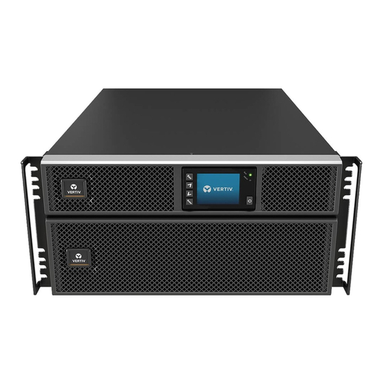
1.2. Front Panels The various GXT5 models have the same general appearance, with the main difference being the receptacle types on the rear panel� Figure 1-1 Front View 1.3. Rear Panels The following figures detail the rear-panel features for each GXT5 model� Figure 1-2 GXT5-750/1000IRT2UXL (XLE) Rear Panel ITEM DESCRIPTION... - Page 10 Liebert® IntelliSlot™ port Ventilation Hole External-battery-cabinet connector Input circuit-breaker reset button, 10-A Non-programmable C13 output receptacles Programmable C13 output receptacles C14 input-power plug and cable Terminal-block/Dry-contact communication connectors RS-232 port RS-485 port USB port Vertiv | Liebert® GXT5™ | Installer/User Guide...
- Page 11 Figure 1-4 GXT5-2000IRT2UXL (XLE) Rear Panel ITEM DESCRIPTION Liebert® IntelliSlot™ port Ventilation Hole External-battery-cabinet connector Non-programmable C13 output receptacles Programmable C13 output receptacles C20 input-power plug and cable Input circuit-breaker reset button, 16-A Terminal-block/Dry-contact communication connectors RS-232 port RS-485 port USB port GXT5 Description...
- Page 12 Non-programmable C19 output receptacle Output circuit-breaker reset buttons, 10-A Non-programmable C13 output receptacles Programmable C13 output receptacles C20 Input-power plug and cable Input circuit-breaker reset button, 20-A Terminal-block/Dry-contact communication connectors RS-232 port RS-485 port USB port Vertiv | Liebert® GXT5™ | Installer/User Guide...
- Page 13 Figure 1-6 GXT5-3KL620RT2UXL Rear Panel Not available in Asia-Pacific region. ITEM DESCRIPTION Liebert® IntelliSlot™ port Ventilation Hole External-battery-cabinet connector Input power cable, L6-20P Output circuit-breaker reset buttons, 20-A Output cable, L6-20R Output circuit-breaker reset buttons, 15-A Output cables, L6-15R Input circuit-breaker reset button Terminal-block/Dry-contact communication ports RS-232 port RS-485 port...
- Page 14 External-battery-cabinet connector Input power cable, L6-30P Output circuit-breaker reset buttons, 20-A Output cable, L6-30R Output circuit breakers, 15-A Output cables, L6-15R Input circuit-breaker reset button Terminal-block/Dry-contact communication ports RS-232 port RS-485 port USB port Vertiv | Liebert® GXT5™ | Installer/User Guide...
-
Page 15: 1�4� Battery Cabinet
1.4. Battery Cabinet Optional battery cabinets are available for the UPS, and include a single battery-connector cable� Up to 10 battery cabinets may be connected in parallel to the UPS, and up to 6 can be detected using EBC - detection� See Table page 61, for the cabinet specifications�... - Page 16 Filter electromagnetic interference (EMI) and radio frequency interference (RFI)� Minimize interference present in EMI/RFI Filters the utility power and protect devices connected on the same branch as the UPS� Outlet group Programmable output receptacles� Outlet group General output receptacles� Vertiv | Liebert® GXT5™ | Installer/User Guide...
-
Page 17: 1� 6 � Ups States And Operating Modes
1.6. UPS States and Operating Modes NOTE: See LED Indicators page 31, for description of the run-indicator and alarm-indicator LEDs mentioned in this section� 1.6.1. Normal Mode When utility power is normal, Normal mode employs the rectifier and inverter to provide voltage- and frequency- stabilized power to the load�... -
Page 18: 1�6�5� Eco Mode
NOTE: During Eco mode, if a bypass-failure or abnormal-bypass-voltage notification appears when the output is not overloaded, the UPS will transfer to Normal Mode� However, if a notification showing bypass failure or abnormal bypass voltage appears when the output is overloaded, the UPS will shut down the bypass� Vertiv | Liebert® GXT5™ | Installer/User Guide... - Page 19 This page is intentionally left blank� GXT5 Description...
-
Page 20: Chapter 2: Installation
• Inspect the UPS for shipping damage� If any shipping damage is found, report it to the carrier and your local Vertiv representative immediately� • Check the accessories included against the packing list� If there is any discrepancy, contact your local Vertiv representative immediately�... -
Page 21: 2�2� Pre-Installation Preparation
2.2. Pre-installation Preparation • Install the UPS indoors in a controlled environment, where it cannot be accidentally turned Off� The installation environment should meet the specifications listed in � Specifications page 57 • Place the UPS in an area of unrestricted air-flow around the unit, away from water, flammable liquids, gases, corrosives, and conductive contaminants�... -
Page 22: 2�3�1� Tower Installation
The GXT5 is heavy� The UPS must be installed as near the bottom of a rack as possible� If placed too high, it can make the rack top-heavy and prone to tipping over� For unit weights, see Specifications page Vertiv | Liebert® GXT5™ | Installer/User Guide... -
Page 23: 2�4� Installing External Battery Cabinets
61� Take proper precautions when lifting them� To install the EBC(s): 1� Inspect the EBC for freight damage� Report damage to the carrier and your local dealer or Vertiv representative� 2� For tower installation: • An additional set of support-base extensions ships with each EBC�... - Page 24 Figure 2-2 EBCs connected to the UPS ITEM DESCRIPTION EBC-detection dry-contact port (See Table 2�2 on page 22, for details�) EBC connector EBC-detection port External battery cabinet External battery cabinet Vertiv | Liebert® GXT5™ | Installer/User Guide...
-
Page 25: 2�5� Connecting Ac Input Power
2.5. Connecting AC Input Power Ensure that all the loads are turned Off� Prepare an input power supply that is properly protected by a circuit breaker in accordance with national and local electrical codes� The wall receptacle must be grounded� We recommend installing an upstream circuit breaker of the same series as the input circuit breaker of the GXT5�... - Page 26 NOTE: We recommend that signal-cable lengths be less than 10 ft (3 m), and are kept away from power cabling� I. Connecting IntelliSlot Communication The IntelliSlot ports accepts two optional cards: The Liebert® IntelliSlot™ Relay card (IS-RELAY) card provides dry-contact relay output for custom-wired applications� Vertiv | Liebert® GXT5™ | Installer/User Guide...
- Page 27 2� Insert the card into the slot, and secure with the screws that held the cover plate� To make connections to the card, refer to the Installer/User Guide for the appropriate IntelliSlot card available at www�vertiv�com� II. Connecting to the Dry-contact Port The UPS includes a dry-contact port�...
- Page 28 2� Insert the stripped end into the plug terminals 1 and 2 respectively, then press down the terminals� Make sure that the cables are secure in the plug to prevent failure because of loose contact� Vertiv | Liebert® GXT5™ | Installer/User Guide...
- Page 29 HID/CDC protocol� The CDC protocol is reserved for service software� V. Connecting Sensors to the Control Port The UPS supports the Vertiv temperature and temperature/humidity sensors� The RJ-45 port is used for sensor connection� See the appropriate figure for your model in...
-
Page 30: Chapter 3: Operating The Ups
5� If this is the first-time start-up of the UPS, the Start-up Guidance wizard opens to set the basic parameters of the UPS� Follow the prompts� For detailed description of UPS display functions and settings, see Operation and Display Panel page 29� Vertiv | Liebert® GXT5™ | Installer/User Guide... -
Page 31: 3�3� Transferring To Battery Mode
3.3. Transferring to Battery Mode The UPS operates in Normal mode unless the mains/utility power fails or it is performing a battery self test, then it automatically transfers to Battery mode for the back-up time available or the mains/utility power is restored� Once input power is restored, the UPS returns to Normal mode�... -
Page 32: 3�7� Remote Emergency Power-Off (Repo)
NOTE: A restart delay of 0 seconds for single UPS and 10 seconds for parallel systems is set by default� You can enable/disable auto restart and adjust the delay parameters, see Editing Display and Operation Settings page 46� To manually restart the UPS, press the power button, see Starting-up the UPS page 25� Vertiv | Liebert® GXT5™ | Installer/User Guide... - Page 33 This page is intentionally left blank�...
-
Page 34: Chapter 4: Operation And Display Panel
Run indicator LED, see LED Indicators page 31� Alarm indicator LED, see LED Indicators page 31� Power button, see Table 4-1 on the next page� Menu keys, see Table 4-1 on the next page� LCD panel� Vertiv | Liebert® GXT5™ | Installer/User Guide... - Page 35 Table 4-1 Display-panel Button Functions and Descriptions BUTTON FUNCTION DESCRIPTION Enter Confirm or enter selection� Move to previous page, increase value, move left� Down Move to next page, decrease value, move right� Escape Go back� Power Power-on the UPS, power-off the UPS, transfer to Bypass Mode� NOTE: While the UPS is operating, the LCD will dim and display a screen saver if there is no active alarm or user interaction for two minutes, see Figure...
-
Page 36: 4�1� Led Indicators
Use the function keys to navigate through the menu, and view statuses or select settings in the screens� 4.2.1. Start-up and Flow Screens At start-up, the UPS executes a system test and displays the Vertiv logo screen for about 10 seconds, shown Figure 4-1 page 29�... -
Page 37: 4�2�2� Main Menu
About Product and network information, see About Screen page 45� Maintenance Service-only, service-password protected page for use only by Vertiv service representatives� Figure 4-4 Main Menu ITEM DESCRIPTION ECO-mode indicator Programmable-outlet indicator Ambient temperature and humidity� Only displays when sensors are connected�... -
Page 38: 4�2�3� Status Screen
Input Status Options L-N voltage (V) Line-neutral voltage of input power� L-N current (A) Line-neutral current of input power� Frequency (Hz) Frequency of input of input power� Power Factor Power factor of the input power� Vertiv | Liebert® GXT5™ | Installer/User Guide... - Page 39 Energy (kWh) Input power� Input black count Count of input voltage lost� Input brown count Count of PFC overload to battery� Bypass Status Options L-N voltage (V) Line-neutral voltage of bypass power� Frequency (Hz) Frequency of bypass power� Battery Status Options Battery status Current battery state: charging, discharging, or fully-charged�...
- Page 40 Output power Load Status Options Sout (kVA) Apparent output power� Pout (kVA) Active output power� Power Factor Power factor of output power� Load percent (%) Percentage of recent power rated to output power� Vertiv | Liebert® GXT5™ | Installer/User Guide...
-
Page 41: 4�2�4� Settings Submenu
4.2.4. Settings Submenu The settings screen consists of tabs that list UPS settings for configuration and adjusting parameters with tabs for: • Output • Battery • Monitor • System • Outlets NOTE: Do not change parameter settings or reset to factory defaults when powering-off the UPS� To modify UPS settings: 1�... - Page 42 Sets the duration of the notice to replace the batteries� Dischg protect time Sets the discharge protection time� Equal charge enable Enable/Disabels equal-charge mode� Max chg curr Sets the maximum charge current� Temp compensation Enables/Disables temperature compensation� Vertiv | Liebert® GXT5™ | Installer/User Guide...
- Page 43 Replace battery Activates newly-installed battery packs after replacement� Monitor Settings Options Language Selects the language of the display, see Selecting the Display Language page 48� Options are: • English • French • Portuguese • Spanish • Chinese • German • Japanese •...
- Page 44 • On bypass • On battery • UPS fault Dry contact 6 (Output) Selects the output of dry-contact 6� Options are: • Low battery • On bypass • On battery • UPS fault Vertiv | Liebert® GXT5™ | Installer/User Guide...
- Page 45 Dry contact 1 (Input) Selects the input of dry-contact 1� Options are: • Disable • Battery mode shutdown • Any mode shutdown Dry contact 2 (Input) Selects the input of dry-contact 2� Options are: • Disable • Battery mode shutdown •...
-
Page 46: 4�2�5� Control Screen
2� Use the arrow buttons to move the cursor to the option, then press Enter to selected the control� Figure 4-6 Control Screen Control Options Turn on/off/to bypass Opens the dialog to change operating modes, see Operating the UPS page 25� Vertiv | Liebert® GXT5™ | Installer/User Guide... -
Page 47: 4�2�6� Log Screen
Mute/Unmute audible alarm Silences or un-silences the audible alarm, see Silencing the Audible Alarm page 25� Start/Stop battery manual test Runs the battery self test� Clear faults Clears displayed faults after the issue causing the fault is resolved, see Table 6-2 page 55, for a description of the faults�... - Page 48 Load off due to output The inverter short circuit or the bypass short circuit� Please check it short Load off due to Shutdown in battery mode shutdown on battery Manual power- on Set power-on via LCD panel Vertiv | Liebert® GXT5™ | Installer/User Guide...
- Page 49 Fan fault or not System fault Alarm when model configuration is incorrect� Contact Vertiv Technical support� Internal heat sink temperature too high, and the inverter is off� The alarm can only be silenced if the heat-sink temperature is lower than the alarm setting� The system can automatically start after over temperature fault is solved�...
-
Page 50: 4�2�7� About Screen
Time since startup Elapsed time since start-up of the UPS� Boot FW version Version of MCU boot firmware on the monitor board� Monitor FW version Version of MCU application firmware on the monitor board� Vertiv | Liebert® GXT5™ | Installer/User Guide... -
Page 51: 4�3� Editing Display And Operation Settings
Inverter FW version Version of the inverter firmware� Rectifier FW version Version of the rectifier firmware� 4.3. Editing Display and Operation Settings You may adjust the display settings and UPS configuration via the LCD� The display and operation settings are password protected�... -
Page 52: 4�3�2� Changing The Password
5� Enter the new password, then confirm the new password� A confirmation dialog opens to indicate a successful password change� 6� Press ESC to return to the settings or main menu� Figure 4-10 New and Confirm Password dialogs Vertiv | Liebert® GXT5™ | Installer/User Guide... -
Page 53: 4�3�3� Selecting The Display Language
4.3.3. Selecting the Display Language The LCD is multilingual� The available languages are English, French, Portuguese, Spanish, Chinese, German, Japanese, and Russian� To change the language: 1� At the main menu, select the Settings icon, and press Enter� 2� At the password prompt, use the up-arrow to select the first digit, press the down-arrow to move to the next digit, repeat for each digit, then press Enter to access the settings�... -
Page 54: Chapter 5: Maintenance
• Do not lay tools or metal parts on top of batteries� • Disconnect charging source prior to connecting or disconnecting battery terminals� • If the battery kit is damaged in any way or shows signs of leakage, contact your Vertiv representative immediately�... -
Page 55: 5�1� Replacing Batteries
(such as a rack or server closet)� To obtain the appropriate replacement battery pack(s), refer to Table 5-1 below, and contact your local dealer or Vertiv representative� Table 5-1 Replacement Battery-pack Model Numbers UPS MODEL NUMBER... - Page 56 5� Compare the new and old battery pack to make sure they are the same type and model� If so, proceed with step 6� If they are different, stop and contact your Vertiv representative, or Technical Support, http://www� V ertiv�com/ en-us/support/�...
-
Page 57: 5�2� Charging Batteries
Figure 5-1 Replacing the Battery Pack ITEM DESCRIPTION Battery pack Battery door Front panel 5.2. Charging Batteries The batteries are valve-regulated, non-spillable, lead acid and should be kept charged to attain their design life� The UPS charges the batteries continuously when it is connected to the utility input power� If the UPS will be stored for a long time, We recommend connecting the UPS to input power for at least 24 hours every 4 to 6 months to ensure full recharge of the batteries�... -
Page 58: 5�4� Cleaning The Ups
5� Check the operating mode for Normal mode� If the UPS is operating in Bypass mode, contact Vertiv Technical Support� 6� Check to see if batteries are discharging (operating in Battery mode) and utility power is normal� If so, contact Vertiv Technical Support�... - Page 59 This page is intentionally left blank� Maintenance...
-
Page 60: Chapter 6: Troubleshooting
Inverter fault The inverter is faulty� Contact technical support� Battery aged The battery is bad or weak� Replace the battery� Output short The output connection is short-circuited� Shut-down the equipment and contact technical support� Vertiv | Liebert® GXT5™ | Installer/User Guide... -
Page 61: 6�3� Troubleshooting Ups Issues
Vertiv Technical Support� Visit the GXT5 product page at www�vertiv�com for contact information� When reporting a UPS issue to Vertiv, include the UPS model and serial number� These are located in several places for your ease of location: • On the top panel (rack mount orientation) •... -
Page 62: Chapter 7: Specifications
Up to 10,000 ft� (3000 m) at 77 ºF (25 ºC) without derating Audible Noise <46 dBA max @ 3 ft� (1 m) front and sides <43 dBA max @ 3 ft� (1 m) rear *Only these models are available in the ASIA PACIFIC region. Vertiv | Liebert® GXT5™ | Installer/User Guide... - Page 63 Table 7.1 UPS Specifications, 750 VA and 1000 VA models (continued) MODEL GXT5- 750IRT2UXL* 750IRT2UXLE 1000IRT2UXL* 1000IRT2UXLE RATING 750 VA/750 W 1000 VA/1000 W Agency EN 62040-1:2008+A1:2013; Safety GS mark; UL 1778 5th Edition and CSA 22�2 No� 107�1 EN 62040-2:2006 EN 61000-3-2:2014 EN 61000-3-3:2013 Transportation...
- Page 64 EN 62040-2:2006 EN 61000-3-2:2014 EN 61000-3-3:2013 Transportation ISTA Procedure 1A Surge Immunity ANSI C62�41 Category B IEC 61000-4-5 Surges/Lightning RFI/EMI CISPR22 Class A *Only these models are available in the ASIA PACIFIC region. Vertiv | Liebert® GXT5™ | Installer/User Guide...
- Page 65 Table 7-3 UPS Specifications, 3000 VA Models MODEL GXT5- 3000IRT2UXL* 3000IRT2UXLE 3KL620RT2UXL 3KL630RT2UXL RATING 3000 VA/3000 W 3000 VA/2700 W 3000 VA/3000 W Dimensions, D×W×H, in.(mm) Unit 21�3 x 16�9 x 3�4 (540 × 430 × 85) Shipping 28�2 x 22�4 x 10�3 (717 x 570 x 262) Weight, lb.(Kg) Unit 62 (28�2)
- Page 66 UL 1778 5th Edition and CSA 22�2 No� 107�1 EN 62040-2:2006 EN 61000-3-2:2014 EN 61000-3-3:2013 Safety UL 1778 5th Edition and CSA 22�2 No� 107�1 Transportation ISTA Procedure 1A Surge Immunity ANSI C62�41 Category B RFI/EMI FCC Part 15 (Class A) Vertiv | Liebert® GXT5™ | Installer/User Guide...
-
Page 67: 7�1� Battery Run Times
7.1. Battery Run Times NOTE: Run times in this table are approximate� Times are based on new, fully-charged, standard battery modules at a temperature of 77 °F (25 °C) with 100% resistive UPS loading� Run times listed above can vary by ±5% due to manufacturing variances of the individual batteries�... - Page 68 109�5 82�5 100% 148�5 1644 1311 1252�5 969,5 1015�5 664�5 643�5 447�5 392�5 292�5 265�5 194�5 199�5 +5 EBC 326�5 241�5 157�5 204�5 131�5 241�5 176�5 157�5 114�5 154�5 100% 136�5 122�5 90�5 Vertiv | Liebert® GXT5™ | Installer/User Guide...
- Page 69 Table 3-5 Battery Run Time in Minutes (continued) LOAD PERCENTAGE OF NO. OF EBCS 750 VA 1000 VA 1500 VA 2000 VA 3000 VA CAPACITY 1950 1556�5 1487 1152�5 1207�5 1106 792�5 601�5 622�5 767�5 402�5 441�5 402�5 308�5 470�5 320�5 236�5 242�5...
- Page 70 2537�5 2425�5 1885�5 1973�5 1809�5 1404�5 1303 994�5 1029 1262�5 673�5 736�5 673�5 783�5 541�5 405�5 414�5 +10 EBC 657�5 495�5 565�5 385�5 284�5 495�5 371�5 329�5 295�5 220�5 100% 396�5 294�5 192�5 Vertiv | Liebert® GXT5™ | Installer/User Guide...
- Page 71 This page is intentionally left blank� Specifications...
-
Page 72: Appendix I:technical Support
Customer Service Hotline: 4008876510 India Email: vertiv@customercare�com Customer Service Hotline: 1800 209 6070 Asia Australia: auservice@vertiv�com New Zealand: auservice@vertiv�com Philippines: ph�service@vertiv�com Singapore: sg�service@vertiv�com Malaysia: my�service@vertiv�com Version Information V1�0 (July 19, 2019) Initial Release Vertiv | Liebert® GXT5™ | Installer/User Guide... - Page 73 This page is intentionally left blank�...
- Page 74 © 2019 Vertiv Group Corp. All rights reserved. Vertiv™ and the Vertiv logo are trademarks or registered marks of Vertiv Group Corp. All other names and logos referred to are trade names, trademarks, or registered trademarks of their respective owners. While every precaution has been taken to ensure accuracy and completeness herein.
Need help?
Do you have a question about the Liebert GXT5 and is the answer not in the manual?
Questions and answers