Vertiv Liebert GXT5 Installer/User Manual
Hide thumbs
Also See for Liebert GXT5:
- User manual (118 pages) ,
- Installer and user manual (82 pages) ,
- Installer/user manual (82 pages)
Table of Contents
Advertisement
Quick Links
Advertisement
Table of Contents
Troubleshooting

Subscribe to Our Youtube Channel
Related Manuals for Vertiv Liebert GXT5


Summary of Contents for Vertiv Liebert GXT5
- Page 1 Liebert® GXT5™ UPS Installer/User Guide 200 V to 240 V, 5,000 VA to 20,000 VA...
- Page 2 The products covered by this instruction manual are manufactured and/or sold by Vertiv. This document is the property of Vertiv and contains confidential and proprietary information owned by Vertiv. Any copying, use or disclosure of it without the written permission of Vertiv is strictly prohibited.
-
Page 3: Table Of Contents
2.7.3 Connecting a Remote Emergency Power-off (REPO) Switch 2.7.4 Connecting a USB Cable 2.7.5 Connecting CLI Communication Cables 2.7.6 Connecting Sensors to the Control Port 2.8 Installing a Parallel System 2.8.1 First-time Start-up of Parallel System 2.8.2 Commissioning Parallel System Vertiv | Liebert® GXT5™ Installer/User Guide |... - Page 4 5.5 Removing the Power-distribution Box 6 Troubleshooting 6.1 Symptoms that Require Troubleshooting 6.2 Audible Alarm (Buzzer) 6.2.1 Faults 6.3 Troubleshooting UPS Issues 7 Specifications 7.1 Battery Run Times Appendices Appendix A: Technical Support Vertiv | Liebert® GXT5™ Installer/User Guide |...
-
Page 5: Important Safety Information
IMPORTANT SAFETY INFORMATION IMPORTANT! This manual contains important safety instructions that must be followed during the installation and maintenance of the UPS and batteries. Read this manual thoroughly and the safety and regulatory information, available at https://www.vertivco.com/ComplianceRegulatoryInfo, before attempting to install, connect to supply, or operate this UPS. - Page 6 This page intentionally left blank Vertiv | Liebert® GXT5™ Installer/User Guide...
-
Page 7: Gxt5 Description
1 GXT5 DESCRIPTION The Liebert® GXT5 is a compact, online uninterruptible power system (UPS) that continuously conditions and regulates its output voltage. The Liebert® GXT5 supplies microcomputers and other sensitive equipment with clean sine-wave input power. Upon generation, AC power is clean and stable. However, during transmission and distribution it is subject to voltage sags, spikes, and complete failure that may interrupt computer operations, cause data loss, and damage equipment. -
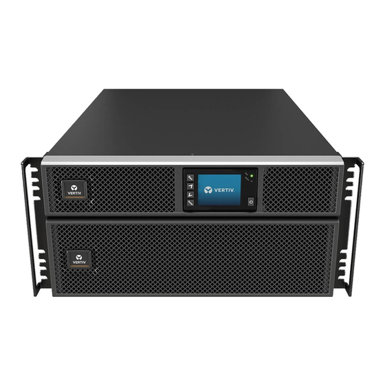
Page 8: Front Panels
16-kVA to 20-kVA models is the same in a rack or tower configuration. Figure 1.1 Front View ITEM DESCRIPTION Operation/Display panel Upper bezel Lower bezel/battery-access door 1.3 Rear Panels The following figures detail the rear-panel features for each GXT5 model. Vertiv | Liebert® GXT5™ Installer/User Guide... - Page 9 Figure 1.2 GXT5-5000/6000IRT5UXLN (XLE) Rear Panel ITEM DESCRIPTION Liebert® IntelliSlot™ port Terminal-block communication connectors RS-485 port USB port RS-232 port REPO connector External-battery-cabinet connector Output circuit breaker Maintenance-bypass breaker Input circuit breaker Removable POD with cable-entry for hard-wire I/O Overload protector, 10-A (x2) Programmable C13 output receptacles (x2) Overload protector, 15-A (x2) C19 output receptacles (x2)
- Page 10 Output circuit breaker Maintenance-bypass breaker Input circuit breaker Removable POD with knock-outs/cable-entry for hard-wire I/O Programmable output circuit breaker, 10-A (x2) C19 output circuit breaker Programmable C13 output receptacles (x2) C19 output receptacles (x2) Vertiv | Liebert® GXT5™ Installer/User Guide...
- Page 11 Figure 1.4 GXT5-8000/10KIRT5UXLN (XLE) Rear Panel ITEM DESCRIPTION Liebert® IntelliSlot™ port Terminal-block communication connectors RS-485 port USB port RS-232 port REPO connector External-battery-cabinet connector Output circuit breaker Maintenance-bypass breaker Bypass circuit breaker Input circuit breaker Removable POD with cable-entry for hard-wire I/O Programmable C19 output receptacle Overload protector, 10-A Programmable C13 output receptacles...
- Page 12 Bypass circuit breaker Input circuit breaker Removable POD with knock-outs/cable-entry for hard-wire I/O Programmable output circuit breaker, 15-A Programmable C19 output receptacle Programmable output circuit breaker, 10-A Programmable C13 output receptacles C19 output circuit breaker, 15-A Vertiv | Liebert® GXT5™ Installer/User Guide...
- Page 13 Figure 1.6 GXT5-16K/20KIRT9UXLN (XLE) Rear Panel ITEM DESCRIPTION Liebert® IntelliSlot™ port Terminal-block communication connectors RS-485 port USB port RS-232 port REPO connector DB9 ports (parallel communication) Input circuit breaker Bypass circuit breaker Knock-outs/cable-entry for hard-wire I/O Output circuit breaker POD breaker Cover for optional POD-installation location External-battery-cabinet connector 1 GXT5 Description...
-
Page 14: Removable Power-Distribution Boxes
The 5-kVA to 10-kVA models ship with the POD installed. This POD includes the input circuit breaker for the UPS, and the features for each POD are detailed in the following figures. Figure 1.7 PD5-CE6HDWRMBS for GXT5-5000/6000IRT5UXLN (XLE) ITEM DESCRIPTION POD Panel view (on rear of unit) POD inner-surface view Quick connect Vertiv | Liebert® GXT5™ Installer/User Guide... - Page 15 Figure 1.8 PD5-CE6HDWRMBSU for GXT5-5000HVRT5UXLN ITEM DESCRIPTION POD Panel view (on rear of unit) POD inner-surface view Quick connect Figure 1.9 PD5-CE10HDWRMBS for GXT5-8000/10KIRT5UXLN (XLE) ITEM DESCRIPTION POD Panel view (on rear of unit) POD inner-surface view Quick connect 1 GXT5 Description...
-
Page 16: Internal Battery Packs
The internal battery packs for all GXT5 models, shown in Figure 1.11 below, are located behind the access door on the front of the UPS. 5-kVA to 10-kVA units have 2 battery packs, and 16-kVA to 20-kVA units have 4 battery packs. Figure 1.11 Internal Battery Pack ITEM DESCRIPTION Handle Connector Vertiv | Liebert® GXT5™ Installer/User Guide... -
Page 17: Major Internal Components And Operating Principle
1.6 Major Internal Components and Operating Principle Figure 1.12 below, shows the UPS operating principle. Table 1.2 on the next page, describes the function of the major components in the UPS. NOTE: Figure 1.12 below, is one example of basic operation. The actual I/O connections for the various models may be divided into different types. -
Page 18: Maintenance Bypass
The charger charges the battery in normal mode. On the front- panel display, the run-indicator (green) is On, the alarm indicator is OFF, and the buzzer is silent. Figure 1.13 on the facing page, shows a diagram of normal mode. Vertiv | Liebert® GXT5™ Installer/User Guide... -
Page 19: Bypass Mode
Figure 1.13 Normal-mode Operation ITEM DESCRIPTION Mains/Utility input (by-pass input) Rectifier/PFC Inverter Battery charger Battery Bypass static switch UPS output 1.7.2 Bypass Mode Bypass mode supplies power to the load from the bypass source (utility power) if an overload or fault occurs during normal operation. -
Page 20: Battery Mode
8 hours before first start-up. NOTE: If utility power fails and the batteries are charged, you may cold-start the UPS in battery mode and use battery power to extend system availability for a time. Vertiv | Liebert® GXT5™ Installer/User Guide... -
Page 21: Eco Mode
Figure 1.15 Battery-mode Operation ITEM DESCRIPTION Mains/Utility input (by-pass input) Rectifier/PFC Inverter Battery charger Battery Bypass static switch UPS output 1.7.4 ECO Mode NOTE: ECO mode is only available on a single-UPS system. The energy-saving ECO mode reduces power consumption by powering the load via bypass if the bypass voltage is normal or by powering the load via the inverter when the bypass voltage is abnormal. -
Page 22: Maintenance Bypass Mode
UPS may shut down without notice and shut-off output power to the load. NOTE: The UPS has no user-serviceable parts. If the UPS malfunctions and requires service, visit http://www.VertivCo.com/en-us/support/ or contact your local Vertiv representative. Vertiv | Liebert® GXT5™ Installer/User Guide... - Page 23 Figure 1.16 Maintenance-bypass Operation ITEM DESCRIPTION Mains/Utility input (by-pass input) Rectifier/PFC Inverter Battery charger Battery Bypass static switch UPS output Maintenance by-pass 1 GXT5 Description...
- Page 24 This page intentionally left blank Vertiv | Liebert® GXT5™ Installer/User Guide...
-
Page 25: Installation
Unpack the UPS and conduct the following checks: • Inspect the UPS for shipping damage. If any shipping damage is found, report it to the carrier and your local Vertiv representative immediately. • Check the accessories included against the packing list. If there is any discrepancy, contact your local Vertiv representative immediately. -
Page 26: Installing The Ups
CAUTION: The GXT5 is heavy. The UPS must be installed as near the bottom of a rack as possible. If placed too high, it can make the rack top-heavy and prone to tipping over. For unit weights, see Specifications on page 61. Vertiv | Liebert® GXT5™ Installer/User Guide... -
Page 27: Installing External Battery Cabinets
• Refer to the instructions included with the rack-mount kit to install. NOTE: Optional slide rails and securing hardware and are sold separately. Please contact your Vertiv representative for options and Vertiv Technical Support for assistance. 3. Verify the that the EBC breaker is in the "Off" position. -
Page 28: Installing A Power-Distribution Box
POD options compatible with your GXT5 model. NOTE: Do not operate the UPS with the POD removed. To shut off all power to the POD and to the load, utility input power must be disconnected. Vertiv | Liebert® GXT5™ Installer/User Guide... -
Page 29: Hardwired Input/Output Connections
To attach the POD on 16-kVA to 20-kVA units: On the rear of the unit, unscrew the two fixing screws from the POD-location cover, see Figure 2.3 below, and remove the cover. 2. Insert the POD receptacles into the ports, and connect the PP75 terminal. 3. -
Page 30: Branch Circuit Breaker
The input circuit breaker on the distribution box does not disconnect power from the manual bypass breaker. Table 2.2 Branch circuit breaker ratings UNIT RATING MAXIMUM BREAKER RATING 5 kVA 60 A 6 kVA 8 kVA 70 A 10 kVA 16 kVA 1-phase: 160 A 3-phase: 50 A 20 kVA Vertiv | Liebert® GXT5™ Installer/User Guide... -
Page 31: Terminal-Block Connections
Figure 2.4 Circuit-breakers diagram ITEM DESCRIPTION Mains/Utility External branch CB Input MB CB Output Input CB Output CB UPS-PFC, battery inverter 2.6.2 Terminal-block Connections On 5-kVA to 10-kVA models, the hard-wire connections to the terminal blocks are made through knockouts on the POD attached to the rear of the unit. On 16-kVA to 20-kVA models, the knockouts are on the rear of the unit. - Page 32 Connecting to Terminal Blocks on 8-kVA and 10-kVA models on the facing page • Connecting to Terminal Blocks on 16-kVA and 20-kVA models on page 30 3. Re-install the cable-entry/conduit-box cover, and tighten the screws. Vertiv | Liebert® GXT5™ Installer/User Guide...
-
Page 33: Connecting To Terminal Blocks On 5-Kva And 6-Kva Models
2.6.3 Connecting to Terminal Blocks on 5-kVA and 6-kVA models These models offer a single type of I/O connection, 1-in 1-out common source. Figure 2.5 below, shows the terminal block. Refer to the details in Terminal-block Connections on page 27, when making the connections. -
Page 34: Connecting To Terminal Blocks On 16-Kva And 20-Kva Models
Figure 2.7 below, shows the 1-in 1-out split-bypass connection. • Figure 2.7 below, shows the 1-in 1-out common-source connection Figure 2.7 3-in 1-out Common-source Connection, 16-kVA and 20-kVA models ITEM DESCRIPTION Output Bypass Input Shorting cable (W01), installed at factory Vertiv | Liebert® GXT5™ Installer/User Guide... - Page 35 Figure 2.8 1-in 1-out Split-bypass Connection, 16-kVA and 20-kVA models ITEM DESCRIPTION Output Bypass Input Shorting cable (W02), included with accessories. Figure 2.9 1-in 1-out Common-source Connection, 16-kVA and 20-kVA models ITEM DESCRIPTION Output Bypass Input Shorting cable (W03), included with accessories 2 Installation...
-
Page 36: Communication Connections
Figure 2.10 below, shows the ports and Table 2.4 on the facing page, describes each port. The I/O dry contact port capacity is 125 Vdc, 0.5 A; 30 Vdc, 1 A Figure 2.10 Dry-contact Port and Pin Layout NOTE: Pins 7 and 8 are shorted before delivery. Vertiv | Liebert® GXT5™ Installer/User Guide... -
Page 37: Connecting A Remote Emergency Power-Off (Repo) Switch
NOTE: The emergency power-off (EPO) action of the UPS closes the rectifier, inverter and static bypass, but it cannot disconnect the UPS mains input inside. To completely disconnect the UPS, disconnect the upstream input circuit breaker when generating the EPO. For details on REPO connection and operation, see Connecting a Remote Emergency Power-off (REPO) Switch below. -
Page 38: Connecting A Usb Cable
The standard, B-type USB port connects the UPS to a network server or other computer system. The USB port supports HID/CDC protocol. The CDC protocol is reserved for service software. To use the HID protocol for monitoring, get the HID protocol from www.VertivCo.com. Vertiv | Liebert® GXT5™ Installer/User Guide... -
Page 39: Connecting Cli Communication Cables
— — 2.7.6 Connecting Sensors to the Control Port The UPS supports the Vertiv temperature and temperature/humidity sensors. The RJ-45 port is used for sensor connection. See the appropriate figure for your model in Rear Panels on page 4, for the location of the port. - Page 40 NOTE: 8-kVA models do not support parallelling at this time. NOTE: You must use Vertiv parallel cables for the connection. NOTE: If a fault occurs during parallel-system operation, shut-off the system and make sure the cables are connected correctly, see Figure 2.12 below.
-
Page 41: First-Time Start-Up Of Parallel System
2.8.1 First-time Start-up of Parallel System IMPORTANT! Do not start the UPS until after the installation is finished, the system is commissioned by an authorized engineer, and the external input circuit breakers are closed. CAUTION: Starting the UPS applies mains/utility power to the output terminals. Make sure that the load power is safe and ready to accept power. -
Page 42: Adding A Single Ups To The Parallel System
4. On the added UPS, close the external I/O switches, wait about 30 seconds to allow the rectifier start-up to finish, then power-on the inverter. 5. Make sure that there are no alarms and that the UPS and the parallel system are operating normally. Vertiv | Liebert® GXT5™ Installer/User Guide... -
Page 43: Operating The Ups
3 OPERATING THE UPS 3.1 Silencing the Audible Alarm The audible alarm may sound during UPS operation. To silence the alarm, press and hold the ESC button for 2 seconds. The button is located on the front-panel display, see Operation and Display Panel page 41. -
Page 44: Transferring From Normal To Bypass Mode
To manually power-off in an emergency, disconnect the terminal connecting the REPO port on the rear of the UPS. If mains/utility power is present, the UPS control circuit remains active even though output power is disabled. To remove all mains/utility power, disconnect the external main-input MCB. Vertiv | Liebert® GXT5™ Installer/User Guide... -
Page 45: Operation And Display Panel
4 OPERATION AND DISPLAY PANEL The operation/display panel includes LED indicators, function keys, and an LCD interface to configure and control UPS operation. Figure 4.1 UPS Front-panel Display ITEM DESCRIPTION Run indicator LED, see LED Indicators on the next page. Alarm indicator LED, see LED Indicators on the next page. -
Page 46: Led Indicators
Table 4.2 LED Functions INDICATOR LED COLOR LED STATE INDICATES: UPS has output Run indicator Green Blinking Inverter is starting UPS has no output Yellow Alarm occurs Alarm indicator Fault occurs No alarm, no fault Vertiv | Liebert® GXT5™ Installer/User Guide... -
Page 47: Lcd Menu And Screens
4.2.1 Start-up and Flow Screens At start-up, the UPS executes a system test and displays the Vertiv logo screen for about 10 seconds, shown in Figure 4.1 on page 41. After the test completes, an overview screen shows status information, the active (green) power path, and the non-working power path (gray), see 4.2.1 above. - Page 48 About Product and network information, see About Screen on page 50. Maintain Service-only, proprietary-password-protected page for use only by Vertiv service representatives. Figure 4.4 Main Menu ITEM DESCRIPTION ECO-mode indicator Ambient temperature and humidity. Only displays when sensors are connected.
- Page 49 Figure 4.5 Status-screen tabs ITEM DESCRIPTION Screen tabs with Input tab selected. Settings Submenu The settings screen consists of tabs that list UPS settings for configuration and adjusting parameters with tabs for: • Output • Battery • Parallel • Monitoring NOTE: To adjust the settings, you must enter a password.
- Page 50 Internal communication is abnormal, please check the communication cables are connected Communication fail correctly or not Rectifier fault The rectifier is faulty and off The discharger is faulty, because the bus voltage exceeds the setting range when discharger starts or DC/DC fault soft starts Vertiv | Liebert® GXT5™ Installer/User Guide...
- Page 51 Table 4.4 Alarm-message descriptions (continued) MESSAGE DESCRIPTION The inverter is off when DC bus voltage is faulty. The load will transfer to bypass if the bypass is DC bus abnormal available Charger fault The charger output voltage is abnormal, and the charger is off Aux.
- Page 52 In parallel system, all the devices powered by the battery inverter have battery low voltage pre- warning warning Battery test started The battery periodic self-test and manual self-test started Battery test stopped The battery periodic self-test or manual self-test finished Vertiv | Liebert® GXT5™ Installer/User Guide...
- Page 53 Table 4.4 Alarm-message descriptions (continued) MESSAGE DESCRIPTION EOD turn off The inverter is off due to EOD. Check the mains power-off state and recover the mains in time Guaranteed shutdown Under forced EOD mode, the battery discharging finished, then system shuts down During the UPS operation, the system checks that the heat sink temperature exceeds the setting range.
- Page 54 2. Use the arrow buttons to move the cursor left/right and select a tab, then press Enter to display the information for the selected tab. Figure 4.8 About Screen Tabs ITEM DESCRIPTION Screen tabs with Efficiency tab selected. Vertiv | Liebert® GXT5™ Installer/User Guide...
-
Page 55: Editing Display And Operation Settings
4.3 Editing Display and Operation Settings You may adjust the display settings and UPS configuration via the LCD. The display and operation settings are password projected. The default password is 111111 (six ones). NOTE: We recommend that you change the password to protect your system and equipment and record the new password and store it in an accessible location for later retrieval. -
Page 56: Selecting The Display Language
3. Use the arrow buttons to select the Monitor tab, then press Enter. 4. Use the down arrow to highlight Date or Time, then press Enter. 5. Use the up/down arrows to select the date/time, then press Enter to confirm. Vertiv | Liebert® GXT5™ Installer/User Guide... -
Page 57: Maintenance
• Disconnect charging source prior to connecting or disconnecting battery terminals. • If the battery kit is damaged in any way or shows signs of leakage, contact your Vertiv representative immediately. • Handle, transport, and recycle batteries in accordance with local regulations. - Page 58 Read all safety cautions before proceeding. A trained user can replace the internal battery pack when the UPS is in a restricted access location (such as a rack or server closet). To obtain the appropriate replacement battery pack(s), refer to Table 5.1 below, and contact your local dealer or Vertiv representative.
-
Page 59: Charging Batteries
6. Line-up and slowly push-in each replacement battery pack. until 2/3 of the length is in the bay, then lift up and continue to push smoothly until the battery pack is fully inserted in the bay. The battery is fully-inserted if the battery door fits flush against the UPS. 7. -
Page 60: Checking Ups Operation
Vertiv Technical Support. 6. Check to see if batteries are discharging (operating in Battery mode) and utility power is normal. If so, contact Vertiv Technical Support. 5.4 Cleaning the UPS WARNING! Risk of electric shock. Can cause injury or death. Disconnect all local and remote electric power supplies before working with the UPS. - Page 61 7. Remove the power distribution box from the UPS and set it aside. 8. On the rear of the panel, loosen the screws of the protective cover for the connectors, slide it over the connectors, and tighten the screws. NOTE: The captive screws and maintenance-bypass breaker cover is similar for all 5- to 10-kVA models. Figure 5.2 below, shows an example on the 5-kVA/6-kVA model.
- Page 62 This page intentionally left blank Vertiv | Liebert® GXT5™ Installer/User Guide...
-
Page 63: Troubleshooting
6 TROUBLESHOOTING This section indicates various UPS symptoms you may encounter and provides a troubleshooting guide in the event the UPS develops a problem. Use the following information to determine whether external factors caused the problem and how to remedy the situation. 6.1 Symptoms that Require Troubleshooting The following symptoms indicate the UPS is malfunctioning: •... -
Page 64: Troubleshooting Ups Issues
Vertiv Technical Support. Visit the GXT5 product page at www.VertivCo.com for contact information. When reporting a UPS issue to Vertiv, include the UPS model and serial number. These are located in several places for your ease of location: •... -
Page 65: Specifications
7 SPECIFICATIONS Table 7.1 UPS Specifications, 5-kVA and 6-kVA models MODEL: GXT5- 5000IRT5UXLN 5000IRT5UXLE 5000HVRT5UXLN 6000IRT5UXLN 6000IRT5UXLE RATING 5000 VA/5000 W 6000 VA/6000 W Dimensions, mm (in.) Unit, WxDxH 430×630×217(16.9×24.8×8.5) Shipping, WxDxH 646×816×520(25.4×32.1×20.5) Weight, kg (lb) Unit 70.8 (156) 71.1 (156.7) 70.8 (156) Shipping 92(202.8) 89 (196.2) 92(202.8) - Page 66 Level 4, Criteria A Criteria A IEC/EN EN61000-4-5, IEC/EN EN61000-4-5, Level 4, IEC/EN EN61000-4-5, Level 4, Surge Immunity Level 4, Criteria A; Criteria A Criteria A ANSI C62.41 Category B Transportation ISTA Procedure 1E Vertiv | Liebert® GXT5™ Installer/User Guide...
- Page 67 Table 7.2 UPS Specifications, 8-kVA and 10-kVA models MODEL: GXT5- 8000IRT5UXLN 8000IRT5UXLE 8000HVRT5UXLN 10KIRT5UXLN 10KIRT5UXLE 10KHVRT5UXLN RATING 8000 VA/8000 W 10000 VA/10000 W Dimensions, mm (in.) Unit, WxDxH 430×630×217(16.9×24.8×8.5) Shipping, WxDxH 646×816×520(25.4×32.1×20.5) Weight, kg (lb) Unit 74.5 (164.2) 75.5 (166.4) 74.5 (164.2) 75.5 (166.4) Shipping 95 (209.4) 93 (205)
- Page 68 -15 to 40 (5 to 104) (°F) Relative Humidity 0 – 95% non-condensing Operating Up to 3,000 m (9,842.5 ft) at 25°C (77°F) without derating Elevation Audible Noise <55 dBA,at 1 meter from the front, <50 dBA, at 1 meter from rear or sides Vertiv | Liebert® GXT5™ Installer/User Guide...
- Page 69 Table 7.2 UPS Specifications, 8-kVA and 10-kVA models (continued) MODEL: GXT5- 8000IRT5UXLN 8000IRT5UXLE 8000HVRT5UXLN 10KIRT5UXLN 10KIRT5UXLE 10KHVRT5UXLN RATING 8000 VA/8000 W 10000 VA/10000 W Agency IEC62040- IEC62040-1:2008 1:2008 version, IEC62040-1:2008 version, Safety IEC62040-1:2008 version, GS mark version, GS mark; GS mark; GS mark UL1778, c-UL listed UL1778, c-UL listed IEC/EN/AS 62040- IEC/EN/AS...
- Page 70 Back-up time See Table 7.7 on page 69. See Table 7.6 on page 69. Upper-limit selections +10%, +15%, +20%; default +10%. Lower-limit selections -10%, -15%, -20%; default -15% Disable-bypass operation When the input frequency prevents synchronous operation. Vertiv | Liebert® GXT5™ Installer/User Guide...
- Page 71 Table 7.3 UPS Specifications, 16-kVA and 20-kVA models (continued) MODEL: GXT5- 16KIRT9UXLN 16KIRT9UXLE 20KIRT9UXLN 20KIRT9UXLE RATING 16000 VA/16000 W 20000 VA/20000 W Environmental Operating Temperature, °C (°F) 0 to 40 (32 to 104) (no derating) Storage Temperature, °C (°F) -15 to 40 (5 to 104) Relative Humidity 0 – 95% non-condensing Operating Elevation...
- Page 72 Storage Temp, °C (°F) -15 to 40 (5 to 104) Relative Humidity 0 – 95% non-condensing Operating Elevation Up to 3,000 m (9,842.5 ft.) at 25°C (77°F) Agency IEC62040-1:2008version,GS mark; Safety UL1778, c-UL listed Transportation ISTA Procedure 1E Vertiv | Liebert® GXT5™ Installer/User Guide...
-
Page 73: Battery Run Times
7.1 Battery Run Times Table 7.6 Battery Run Time, 20-kVA Models BACKUP TIME (MIN) NO. OF TOTAL EBCS NO. OF AH 18KVA 16KVA 14KVA 12KVA 8KVA 6KVA 4KVA 2KVA 14.5 26.0 62.5 UPS+1 10.0 12.0 15.0 19.5 26.5 39.0 64.0 136.0 UPS+2 13.0... - Page 74 67.0 82.5 105.5 145.0 229.5 471.0 4 EBC UPS+ 45.5 52.0 59.5 69.5 82.5 101.0 128.5 181.5 283.0 572.5 5 EBC UPS+ 55.5 62.5 71.5 83.0 98.5 120.0 155.0 218.0 336.5 674.5 6 EBC Vertiv | Liebert® GXT5™ Installer/User Guide...
- Page 75 Table 7.10 Battery Run Time, 6-kVA Models BACKUP TIME (MIN) TOTA L NO. 5.4KV 4.8KV 4.2KV 3.6KV 2.4KV 1.8KV 1.2KV 0.6KV OF AH 11.0 14.5 19.5 29.0 48.0 100.0 UPS+1 14.5 17.0 20.0 24.0 30.0 38.5 50.5 70.0 107.0 226.0 UPS+ 26.0 30.5...
- Page 76 This page intentionally left blank Vertiv | Liebert® GXT5™ Installer/User Guide...
-
Page 77: Appendices
APPENDICES Appendix A: Technical Support Our Technical Support staff is ready to assist you with any installation or operating issues you may encounter with your Liebert® product. Please call or e-mail us: In Europe, Middle East, and Asia: EMEA Multi-Language Technical support: e: eoc@vertivco.com p: Toll free 0080011554499 p: Toll +39 02 98250222... - Page 78 This page intentionally left blank Vertiv | Liebert® GXT5™ Installer/User Guide...
- Page 79 Vertiv | Liebert® GXT5™ Installer/User Guide...
- Page 80 VertivCo.com | Vertiv Headquarters, 1050 Dearborn Drive, Columbus, OH, 43085, USA © 2018 Vertiv Co. All rights reserved. Vertiv and the Vertiv logo are trademarks or registered trademarks of Vertiv Co. All other names and logos referred to are trade names, trademarks or registered trademarks of their respective owners. While every precaution has been taken to ensure accuracy and completeness herein, Vertiv Co.
Need help?
Do you have a question about the Liebert GXT5 and is the answer not in the manual?
Questions and answers