
Related Manuals for Cypress CY8CKIT-059 PSoC 5LP Prototyping Kit


Summary of Contents for Cypress CY8CKIT-059 PSoC 5LP Prototyping Kit
- Page 1 CY8CKIT-059 ® PSoC 5LP Prototyping Kit Guide Doc. #: 001-96498 Rev. *G Cypress Semiconductor 198 Champion Court San Jose, CA 95134-1709 www.cypress.com...
- Page 2 Cypress is not liable, in whole or in part, and you shall and hereby do release Cypress from any claim, damage, or other liability arising from or related to all Unintended Uses of Cypress products.
-
Page 3: Table Of Contents
Contents Safety Information 1. Introduction Kit Contents .........................7 PSoC Creator ......................8 1.2.1 PSoC Creator Code Examples ................9 1.2.2 Kit Code Examples..................10 1.2.3 PSoC Creator Help ..................10 1.2.4 Component Datasheets .................11 Getting Started......................11 Additional Learning Resources..................11 Technical Support......................12 Document Conventions .....................12 2. - Page 4 Contents 5. Code Examples Using the Kit Code Examples ..................31 CE195352_PSoC_5LP_Blinking_LED ..............35 CE195277_ADC_and_UART ..................37 CE195394_HID_Mouse .....................38 Appendix 39 PSoC 5LP Prototyping Kit Schematics ................39 Programming PSoC 5LP Prototyping Kit Using MiniProg3/KitProg ........41 Bill of Materials ........................42 Revision History CY8CKIT-059 PSoC® 5LP Prototyping Kit Guide, Doc. #: 001-96498 Rev. *G...
-
Page 5: Safety Information
Safety Information Regulatory Compliance ® The CY8CKIT-059 PSoC 5LP Prototyping Kit is intended for use as a development platform for hardware or software in a laboratory environment. The board is an open system design, which does not include a shielded enclosure. This may cause interference to other electrical or electronic devices in close proximity. - Page 6 General Safety Instructions ESD Protection ESD can damage boards and associated components. Cypress recommends that you perform procedures only at an ESD workstation. If such a workstation is not available, use appropriate ESD protection by wearing an antistatic wrist strap attached to the chassis ground (any unpainted metal surface) on your board when handling parts.
-
Page 7: Introduction
Introduction Thank you for your interest in the CY8CKIT-059 PSoC 5LP Prototyping Kit. This kit is designed as an easy-to-use and inexpensive prototyping platform. The PSoC 5LP Prototyping Kit supports the PSoC 5LP device family, delivering a complete system solution for a wide range of embedded ®... -
Page 8: Psoc Creator
Figure 1-2. PSoC Creator Features PSoC Creator also enables you to tap into an entire tool ecosystem with integrated compiler chains and production programming programmers for PSoC devices. For more information, visit www.cypress.com/psoccreator. CY8CKIT-059 PSoC® 5LP Prototyping Kit Guide, Doc. #: 001-96498 Rev. *G... -
Page 9: Psoc Creator Code Examples
Introduction 1.2.1 PSoC Creator Code Examples PSoC Creator includes a large number of code examples. These examples are available from the PSoC Creator Start Page, as Figure 1-3 on page 9 shows. Code examples can speed up your design process by starting you off with a complete design, instead of a blank page. -
Page 10: Kit Code Examples
Introduction Figure 1-4. Code Example Projects with Sample Code 1.2.2 Kit Code Examples This kit includes a number of code examples, which can be used to quickly evaluate the functionality of this kit. These examples are described in the Code Examples chapter on page 1.2.3 PSoC Creator Help Visit the... -
Page 11: Component Datasheets
■ MiniProg3, and the bill of materials (BOM). Additional Learning Resources Cypress provides a wealth of information at www.cypress.com to help you to select the right PSoC device for your design, and to help you to quickly and effectively integrate the device into your design. -
Page 12: Technical Support
PSoC developers ■ discussing the next generation embedded systems on Cypress Developer Community Forums. Technical Support If you have any questions, our technical support team is happy to assist you. You can create a support request on the Cypress Technical Support page. -
Page 13: Software Installation
Before You Begin All Cypress software installations require administrator privileges, but these are not required to run the software after it is installed. Close any other Cypress software that is currently running before installing the kit software. Note: By default, the kit contents are installed in the C:\Program Files\Cypress folder, for a 32-bit machine and C:\Program Files (x86)\Cypress, for a 64-bit machine. - Page 14 Following is the required software: a. PSoC Creator 4.2: This software is available for download separately from the kit at www.cypress.com/psoccreator. PSoC Creator 4.2 installer automatically installs the following additional software: –...
-
Page 15: Uninstall Software
Uninstall Software The software can be uninstalled using one of the following methods: 1. Go to Start > All Programs > Cypress > Cypress Update Manager and select the Uninstall button. 2. Go to Start > Control Panel > Programs and Features for Windows 7 or Add/Remove Programs for Windows XP;... -
Page 16: Kit Operation
Kit Operation This chapter introduces you to the different features of the PSoC 5LP Prototyping Kit. This primarily includes the programming/debugging functionality, KitProg USB-UART and USB-I2C bridges, and the method to update the KitProg firmware. Theory of Operation Figure 3-1 shows the block diagram for the PSoC 5LP Prototyping Kit. -
Page 17: Kitprog
The KitProg is a multi-functional system, which includes a programmer, debugger, USB-I2C bridge, and a USB-UART bridge. The Cypress PSoC 5LP device is used to implement KitProg functionality. The KitProg is integrated in most PSoC development kits. For more details on the KitProg... - Page 18 Kit Operation 2. Open the desired project in PSoC Creator by selecting File > Open > Project/Workspace. This provides the option to browse to and open a previously saved project. If you want to open one of the code examples provided with the kit, follow the instructions in the Code Examples chapter on page 3.
-
Page 19: Debugging Using Psoc Creator
Kit Operation 3.3.2 Debugging using PSoC Creator To debug the project using PSoC Creator, follow steps 1 to 3 from Programming using PSoC Creator on page 17 followed by: 1. Click the Debug icon or press [F5]. Alternatively, you can use the option Debug > Debug. 2. -
Page 20: Hardware
Hardware Board Details The PSoC 5LP Prototyping Kit consists of the following blocks: PSoC 5LP device ■ PSoC 5LP header ports J1 and J2 ■ Micro-USB connector, J6 ■ PSoC 5LP program/debug JTAG header, J5 ■ KitProg (PSoC 5LP) device ■... -
Page 21: Hardware Details
Hardware Hardware Details 4.2.1 Target Board The target board uses the PSoC 5LP family device. PSoC 5LP is the industry's most integrated programmable SoC, integrating high-precision and programmable analog and digital peripherals, ® and an Arm Cortex™-M3 CPU. The PSoC 5LP features a high-precision analog-to-digital converter (ADC), programmable amplifiers, flexible digital subsystem, unmatched parallel co-processing digital filter block (DFB), high-throughput peripherals such as DMA, CAN, and USB, and standard communication and timing peripherals. -
Page 22: Kitprog Board
Hardware 4.2.2 KitProg Board PSoC 5LP on the KitProg board is used to program and debug the target PSoC 5LP device. The KitProg PSoC 5LP connects to the USB port of the PC through the PCB USB connector and to the SWD interface of the target PSoC 5LP device. -
Page 23: Power Supply System
Hardware 4.2.3 Power Supply System The power supply system on this board is dependent on the source of the power. For most applications, you can use the 5-V supply from the USB connection to power the system. You can also connect an external power supply to the board for low-voltage applications. The kit supports the following connections: 5 V from the KitProg USB ■... -
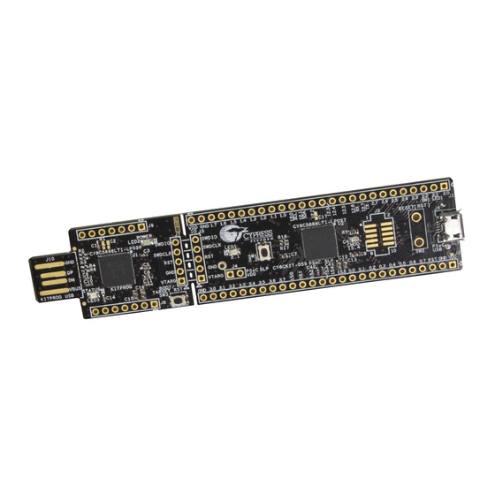
Page 24: Board Separation (Snapping)
Hardware 4.2.4 Board Separation (Snapping) The PSoC 5LP Prototyping Kit consists of both a PSoC 5LP and a KitProg board. To separate the two boards for testing or development, break the two boards apart at the built-in perforated edge. The easiest method of separating the two boards is to place the kit on the edge of a table, where the edge of the table is directly below the perforated edge and the smaller KitProg board is off the table edge. - Page 25 Hardware Table 4-1. J1 Header Pin Details Table 4-2. J2 Header Pin Details PSoC 5LP Prototyping Kit GPIO Header (J1) PSoC 5LP Prototyping Kit GPIO Header (J2) Signal Description Signal Description J1_01 P2.0 GPIO J2_01 Power J1_02 P2.1 GPIO/LED J2_02 Ground J1_03 P2.2...
- Page 26 Hardware 4.2.5.2 Functionality of J7 and J3 Headers (PSoC 5LP to KitProg) The KitProg and target boards each contain a 1x5-pin header. These headers provide a physical connection between the two devices. Specifically, the connection includes the SWD interface, required to program/debug the target PSoC 5LP device, power, ground, and reset. Figure 4-6.
- Page 27 Hardware 4.2.5.3 Functionality of J8 and J9 Headers (KitProg) The KitProg board contains two dual-inline headers (J8 and J9). These headers are both 1x7-pin- headers, used to pull out several pins of PSoC 5LP to support advanced features like a low-speed oscilloscope and a low-speed digital logic analyzer.
-
Page 28: User And Passive Inputs
Hardware 4.2.6 User and Passive Inputs 4.2.6.1 Push Button The target PSoC 5LP board contains a single push button connected to the P2.2 pin on the PSoC 5LP device. This button can be used for general user inputs or to control different states in an application. - Page 29 Hardware 4.2.6.3 LEDs The PSoC 5LP Prototyping Kit contains three LEDs: Amber LED: Indicates that the board is powered from the PCB USB connector. This LED will not ■ light when the board is powered from the micro-USB connector or from VDD or VTARG directly. Green LED: Indicates the KitProg status, connected to P3.1 of the KitProg PSoC 5LP device.
- Page 30 Hardware 4.2.6.4 System Capacitors The PSoC 5LP Prototyping Kit has seven capacitors, which are used when ADC operation at high frequencies, CapSense, or external 32-kHz crystal oscillator is required in the application. Four ADC bypass capacitors: Required for proper ADC sampling at high frequencies: ■...
-
Page 31: Code Examples
Using the Kit Code Examples Follow these steps to open and use the code examples. 1. Launch PSoC Creator from the Windows Start menu (Start > All Programs > Cypress > PSoC Creator<version> > PSoC Creator <version>). 2. On the Start page, click CY8CKIT-059 under Start > Kits. A list of code examples appears, as... - Page 32 Code Examples 4. Build the code example by choosing Build > Build <Project Name>, as shown in Figure 5-2. A .hex file is generated after the build process. Figure 5-2. Open Code Example from PSoC Creator 5. Connect the PSoC 5LP Prototyping Kit to the PC using the KitProg PCB USB port, J10 as described in Figure 3-2 on page 17 to program the kit with this code example.
- Page 33 Code Examples 7. PSoC Creator opens the programming window if the device is not yet acquired. Select KitProg and click the Port Acquire button, as shown in Figure 5-4. Figure 5-4. Port Acquire 8. After the device is acquired, it is shown in a tree structure below the KitProg. Click the Connect button and then OK to exit the window and start programming, as shown in Figure 5-5.
- Page 34 Code Examples 9. From the workspace explorer in PSoC Creator, open the CE195277_ADC_and_UART.pdf as shown in Figure 5-6. Figure 5-6. Project Datasheet - CE195277_ADC_and_UART.pdf CY8CKIT-059 PSoC® 5LP Prototyping Kit Guide, Doc. #: 001-96498 Rev. *G...
-
Page 35: Ce195352_Psoc_5Lp_Blinking_Led
Code Examples CE195352_PSoC_5LP_Blinking_LED This code example demonstrates the use of a fixed-function PWM. The PWM is set up to output a 50-percent duty cycle digital signal with a period of 1 second. This signal can be used to drive an LED for visual testing of the PWM output. - Page 36 Code Examples Figure 5-8. Project Datasheet - CE195352_PSoC_5LP_Blinking_LED.pdf CY8CKIT-059 PSoC® 5LP Prototyping Kit Guide, Doc. #: 001-96498 Rev. *G...
-
Page 37: Ce195277_Adc_And_Uart
Code Examples CE195277_ADC_and_UART This code example implements a simple data collection system using the DelSig ADC and the UART component. The ADC continuously samples an analog input. The resulting samples can be sent to a PC over a UART connection a single sample at a time or continuously. Emulated data, which is just an incrementing number, can also be sent over the UART connection to test the communication. -
Page 38: Ce195394_Hid_Mouse
Code Examples CE195394_HID_Mouse This code example demonstrates the use of the USBFS component to implement a HID mouse. Using the standard HID mouse descriptor, the PSoC enumerates as a mouse on the PC. Once the enumeration is complete the PSoC sends data about the relative movement of the mouse to the PC. A single button is also implemented in the project to emulate the left button, or button 1, on a standard mouse. -
Page 39: Appendix
CYPRESS SEMICONDUCTOR © 2015 This signals will be coming from Kitprog from Breakable area C19 0.01 uF Title Title Title PCA: 121-60210-01 CY8CKIT-059 PSoC 5LP Prototyping Kit CY8CKIT-059 PSoC 5LP Prototyping Kit CY8CKIT-059 PSoC 5LP Prototyping Kit PCB: 600-60243-01 FAB DRW: 610-60235-01 Size... - Page 40 0402 No Load PCA: 121-60210-01 Title Title Title PCB: 600-60243-01 USB FINGER CY8CKIT-059 PSoC 5LP Prototyping Kit CY8CKIT-059 PSoC 5LP Prototyping Kit CY8CKIT-059 PSoC 5LP Prototyping Kit Target PSoC Program/Debug Header FAB DRW: 610-60235-01 Size Size Size Document Number Document Number...
-
Page 41: Programming Psoc 5Lp Prototyping Kit Using Miniprog3/Kitprog
Prototyping Kit supports both power cycle and reset programming modes. Figure A-1. Connecting CY8CKIT-059 to MiniProg3 Note: CY8CKIT-002 MiniProg3 is not part of the PSoC 5LP Prototyping Kit contents and can be purchased from the Cypress Online Store. CY8CKIT-059 PSoC® 5LP Prototyping Kit Guide, Doc. #: 001-96498 Rev. *G... -
Page 42: Bill Of Materials
Bill of Materials Item Qty Reference Value Description Mfr Name Mfr Part Number PCB, 108.89mm × 24.13mm, Cypress High Tg, ENIG finish, 2 layer, 600-60178-01 Semiconductor Color = BLACK, Silk = WHITE C1, C3, C5, C6, C10, C11, C14, C18, C20, C22, CAP .1UF 16V CERAMIC... - Page 43 Switch C&K Components KMR221GLFS SPST-NO, 0.05A, 32V DIODE, TVS, 5V, 350W, TVS1 TVS DIODE Semtech SD05.TCT SOD-323 CY8C5868LTI PSoC 5LP CYC58LP, 67 Cypress -LP039 CY8C5868LTI-LP039 Semiconductor QFN68 CY8C5888LTI PSoC 5LP CYC58LP, 80 Cypress -LP097 CY8C5888LTI-LP097 Semiconductor QFN68 FET DUAL P-CH 20V...
- Page 44 Citizen Finetech BLACK CFS308-32.768KDZF-UB 12.5PF THRU Miyota Label LBL, PCA Label, Vendor Code, Datecode, Serial Cypress Number 121-60210-01 REV Semiconductor 01 (YYWWVVXXXXX) LBL, PCBA Anti-Static Warn- Cypress ing, 10mm × 10mm Semiconductor CY8CKIT-059 PSoC® 5LP Prototyping Kit Guide, Doc. #: 001-96498 Rev. *G...
-
Page 45: Revision History
Revision History ® CY8CKIT-059 PSoC 5LP Prototyping Kit Guide Revision History Document Title: CY8CKIT-059 PSoC® 5LP Prototyping Kit Guide Document Number: 001-96498 Origin of Revision Issue Date Description of Change Change 4668422 02/23/2015 PMAD New kit guide Updated Introduction chapter on page Updated description. - Page 46 Index ® CY8CKIT-059 PSoC 5LP Prototyping Kit Guide Revision History (continued) Document Title: CY8CKIT-059 PSoC® 5LP Prototyping Kit Guide Document Number: 001-96498 Origin of Revision Issue Date Description of Change Change Updated Hardware chapter on page Updated “Board Details” on page Updated Figure 4-1.
- Page 47 Index ® CY8CKIT-059 PSoC 5LP Prototyping Kit Guide Revision History (continued) Document Title: CY8CKIT-059 PSoC® 5LP Prototyping Kit Guide Document Number: 001-96498 Origin of Revision Issue Date Description of Change Change Updated Introduction chapter on page Updated “PSoC Creator” on page Updated “PSoC Creator Code Examples”...
- Page 48 Index ® CY8CKIT-059 PSoC 5LP Prototyping Kit Guide Revision History (continued) Document Title: CY8CKIT-059 PSoC® 5LP Prototyping Kit Guide Document Number: 001-96498 Origin of Revision Issue Date Description of Change Change Updated the code example title in Section 5.2. 6095702 03/12/2018 SAGA Updated...
Need help?
Do you have a question about the CY8CKIT-059 PSoC 5LP Prototyping Kit and is the answer not in the manual?
Questions and answers