
Related Manuals for Cypress PSoC CY8CKIT-062-WiFi-BT


Summary of Contents for Cypress PSoC CY8CKIT-062-WiFi-BT
- Page 1 CY8CKIT-062-WiFi-BT ® PSoC 6 WiFi-BT Pioneer Kit Guide Document Number. 002-22677 Rev. *E Cypress Semiconductor 198 Champion Court San Jose, CA 95134-1709 www.cypress.com...
- Page 2 Cypress is not liable, in whole or in part, and you shall and hereby do release Cypress from any claim, damage, or other liability arising from or related to all Unintended Uses of Cypress products.
-
Page 3: Table Of Contents
Contents Safety Information 1. Introduction Kit Contents .........................7 Hardware Introduction ....................8 1.2.1 CY8CKIT-062-WiFi-BT Board Details ..............8 1.2.2 CY8CKIT-028-TFT Board Details..............10 Software Introduction ....................11 1.3.1 PSoC Creator Overview.................11 1.3.2 WICED Studio Development System Overview..........13 Getting Started......................15 Additional Learning Resources..................15 Technical Support......................15 Documentation Conventions..................16 Acronyms........................16 2. - Page 4 A.2.6 Expansion Connectors ...................64 A.2.7 CapSense Circuit ...................65 A.2.8 LEDs ......................65 A.2.9 Push Buttons....................66 A.2.10 Cypress NOR Flash ..................66 A.2.11 WiFi and Bluetooth Module ................67 A.2.12 USB Host and USB Device Connections ............68 PSoC 6 WiFi-BT Pioneer Board Reworks ..............69 A.3.1 Bypass Protection Circuit on Program and Debug Header (J11)....69...
-
Page 5: Safety Information
General Safety Instructions ESD Protection ESD can damage boards and associated components. Cypress recommends that you perform procedures only at an ESD workstation. If an ESD workstation is unavailable, use appropriate ESD protection by wearing an anti-static wrist strap attached to a grounded metal object. -
Page 6: Introduction
WiFi-BT Pioneer Kit enables you to evaluate and develop your applications using the PSoC 6 MCU. The PSoC 6 MCU is Cypress’ latest, ultra-low-power PSoC specifically designed for wearables and ® IoT products. It is a programmable embedded system-on-chip, integrating a 150-MHz Arm ®... -
Page 7: Kit Contents
Quick Start Guide ■ Figure 1-1. Kit Contents Inspect the contents of the kit; if you find any part missing, contact your nearest Cypress sales office for help: www.cypress.com/support. PSoC® 6 WiFi-BT Pioneer Kit Guide, Document Number. 002-22677 Rev. *E... -
Page 8: Hardware Introduction
CapSense touch-sensing slider (five elements) and two buttons, all of which are capable of both ■ self-capacitance (CSD) and mutual-capacitance (CSX) operation, and a CSD proximity sensor that allows you to evaluate Cypress’ fourth-generation CapSense technology 1.8-V to 3.3-V operation of PSoC 6 MCU is supported. An additional 330-mF super-capacitor is ■... - Page 9 22. PSoC 6 VDD selection switch (SW5) 3. KitProg2 USB Type-C connector (J10) 23. Cypress 512-Mbit serial NOR Flash memory 4. Cypress EZ-PD™ CCG3 Type-C Port Controller with PD (S25FL512S, U4) (CYPD3125-40LQXI, U3) 24. PSoC 6 user LEDs (LED8 and LED9) 5.
-
Page 10: Cy8Ckit-028-Tft Board Details
Introduction 1.2.2 CY8CKIT-028-TFT Board Details Figure 1-3 shows the TFT display shield that has the following features: A 2.4-inch Thin-Film Transistor (TFT) LCD module with 240x320 pixel resolution. ■ A three-axis acceleration and three-axis gyroscopic motion sensor. ■ A PDM microphone for voice input. ■... -
Page 11: Software Introduction
Introduction Software Introduction 1.3.1 PSoC Creator Overview PSoC Creator is a state-of-the-art, easy-to-use IDE. It uses revolutionary hardware and software co- design, powered by a library of fully verified and characterized PSoC Components™ and peripheral driver libraries (PDL), as shown in Figure 1-4. - Page 12 Introduction 1.3.1.1 PSoC Creator Code Examples PSoC Creator includes a large number of code examples. These examples are accessible from the PSoC Creator Start Page, as shown in Figure 1-5 or from the menu File > Code Example. Code examples can speed up your design process by starting you off with a complete design. The code examples also show how to use PSoC Creator Components for various applications.
-
Page 13: Wiced Studio Development System Overview
Introduction 1.3.2 WICED Studio Development System Overview WICED Studio 6.1 (or later) supports WiFi and Bluetooth application development using the CY8CKIT-062-WiFi-BT kit. Tabs and their location in the WICED IDE are as shown in Figure 1-6. Figure 1-6 illustrates the following: 1. - Page 14 Introduction 1.3.2.1 WICED Studio Code Examples WICED Studio includes libraries and code examples supporting both Bluetooth and WiFi platforms. Selecting the 43xxx_Wi-fi Filter will show only WiFi platform related files in the project explorer as shown in Figure 1-7. Application examples can speed up the design process by serving as templates for development. Code examples are located under the apps category (in the Project Explorer window), as shown in Figure 1-8.
-
Page 15: Getting Started
■ components, kit schematics, the bill of materials (BOM), and an FAQ. Additional Learning Resources Cypress provides a wealth of data at www.cypress.com/psoc6 to help you to select the right PSoC device for your design and to help you to quickly and effectively integrate the device into your design. -
Page 16: Documentation Conventions
Introduction Documentation Conventions Table 1-1. Document Conventions for Guides Convention Usage Displays user entered text and source code: Courier New Displays file locations, file names, and reference documentation: Italics Read about the sourcefile.hex file in the PSoC Creator User Guide. Displays keyboard commands in procedures: [Bracketed, Bold] [Enter] or [Ctrl] [C]... - Page 17 Introduction Table 1-2. Acronyms Used in this Document (continued) Acronym Definition personal computer pulse code modulation power delivery pulse density modulation positive temperature coefficient PSoC Programmable System-on-Chip pulse width modulation red green blue successive approximation register SMIF serial memory interfac serial peripheral interface SRAM serial random access memory...
-
Page 18: Psoc Creator
24). Before You Begin To install Cypress software, you will require administrator privileges. However, they are not required to run the software that is already installed. Before you install the kit software, close any other Cypress software that is currently running. - Page 19 3. When you click Next, the installer automatically installs the required software, if it is not present on your computer. Following are the required software: a. PSoC Creator 4.2: This software is available for download separately at www.cypress.com/psoccreator. PSoC Creator 4.2 installer automatically installs the following additional software: PSoC Programmer 3.27.0 Peripheral Driver Library 2.1.0...
- Page 20 8. After the installation is complete, the kit contents are available at the following location: <Install_Directory>\CY8CKIT-062-WiFi-BT PSoC 6 WiFi-BT Pioneer Kit Default location: Windows 7 (64-bit): C:\Program Files (x86)\Cypress\CY8CKIT-062-WiFi-BT PSoC 6 WiFi-BT Pio- neer Kit Windows 7 (32-bit): C:\Program Files\Cypress\CY8CKIT-062-WiFi-BT PSoC 6 WiFi-BT Pioneer Note: For Windows 7/8/8.1/10 users, the installed files and the folder are read-only.
-
Page 21: Programming And Debugging Using Psoc Creator
Using the Kit Code Examples Built in PSoC Creator Follow these steps to open and use the code examples: 1. Launch PSoC Creator from Start > All Programs > Cypress > PSoC Creator <version> > PSoC Creator <version>. PSoC® 6 WiFi-BT Pioneer Kit Guide, Document Number. 002-22677 Rev. *E... - Page 22 PSoC Creator 2. On the Start Page, click CY8CKIT-062-WiFi-BT under Start > Kits. A list of code examples appears, as shown in Figure 2-4. 3. Click the desired code example, select a location to save the project, and click OK. Figure 2-4.
- Page 23 PSoC Creator 8. After the device is acquired, it is shown in a tree structure below the KitProg2/<serial_number>. Click Connect and then OK to exit the window and start programming, as shown in Figure 2-6. Note: PSoC 6 MCUs have both CM0+ and CM4 CPUs. To program, select one of them and click Connect.
-
Page 24: Wiced
Before You Begin To install Cypress software, you will require administrator privileges. However, they are not required to run the software that is already installed. Before you install the kit software, close any other Cypress software that is currently running. -
Page 25: Programming And Debugging In Wiced
Building and Programming a Project for CY8CKIT-062-WiFi-BT in WICED Studio To build and program a project for CY8CKIT-062-WiFi-BT, perform the following steps: 1. To open the WICED IDE on the Windows PC, go to Start > All Programs > Cypress > WICED- Studio. - Page 26 WICED 3. Right-click 43xxx_Wi-Fi in the Make Target window as shown in Figure 3-2 and click New. Figure 3-2. Creating New Make Target 4. Enter snip.scan-CY8CKIT_062 download_apps download run in the Target name field and click OK. Note: The list of all commands that can be provided in the Make target is listed in <WICED-SDK installation directory>/ 43xxx_Wi-Fi/Makefile.
- Page 27 WICED 6. Double-click (alternatively right-click and select Build Target) the snip.scan-CY8CKIT_062 download_apps download run make target to build and download it to the CY8CKIT-062- WiFi-BT. The project is built and programmed into the CY8CKIT-062-WiFi-BT, as shown in Figure 3-3. Figure 3-3. Successful Build and Program 7.
- Page 28 WICED c. Go to Setup > Serial port, initiate a connection with the Serial port number from the Device Manager on the PC. Note: The exact Port number will vary with the corresponding PC port. d. Press the Reset button on the CY8CKIT-062-WiFi-BT to view the application start-up mes- sages.
-
Page 29: Debugging A Project Using Breakpoints
WICED 3.4.2 Debugging a Project using Breakpoints After programming a project, it is possible to debug it in CY8CKIT-062-WiFi-BT using the built-in debugger. Note that the scan example used in Building and Programming a Project for CY8CKIT-062-WiFi-BT in WICED Studio IDE on page 25 is also used here. - Page 30 WICED d. To switch between perspectives use the “C/C++” or “Debug” icon at the top right corner of screen. Figure 3-5. Debugging Project 3. Open the scan.c file from the Project Explorer window. Click the line with WPRINT_APP_INFO( ( "Waiting for scan results...\n" ) ); and press the [Ctrl +Shift+B] keys on your keyboard.
- Page 31 WICED 6. To terminate the Debugging session, click Run > Terminate, or click on the red Square icon. Once you terminate the session, click C/C++ in the upper right corner to return to the C/C++ per- spective. Figure 3-6. Placing Breakpoint in Code 7.
- Page 32 WICED 8. Right-click the desired breakpoint check box and click Breakpoint Properties…. Click the last_built.elf check box, as shown in Figure 3-8. The check mark appears before the actual breakpoint indicating its association with the current execution. Figure 3-7. Show Breakpoints Icon Figure 3-8.
-
Page 33: Kit Code Example
24. To build and program the WICED based project of the CY8CKIT-062-WiFi-BT kit, perform the following steps: 1. To open the WICED IDE on Windows PC, go to Start > All Programs > Cypress > WICED- Studio. 2. Locate the WICED WiFi-SDK directory in your PC. The default location is C:\Users\<user name>\Documents\WICED-Studio-6.1\43xxx_WiFi, as shown in... - Page 34 WICED 4. Open the resources\apps folder and copy the CE222494_PSoC6_WICED_WiFi folder into WICED-Studio-6.1\43xxx_Wi-Fi\resources\apps. If WICED Studio 6.1 (or later) is opened with 43xxx_Wi-Fi as the WICED Filter, then the new folders appear as shown in Figure 3-10. If the projects are not visible in WICED Studio 6.1 (or later), then right-click the 43xxx_Wi-Fi folder in Project Explorer and click Refresh, as shown in Figure 3-10.
- Page 35 WICED Figure 3-11. Refresh Top Folder 5. In the Make Target window, right-click and select New, and give it the following Target Name: demo.CE222494_PSoC6_WICED_WiFi-CY8CKIT_062 download_apps download run (see Figure 3-12). Figure 3-12. Creating New Make Target PSoC® 6 WiFi-BT Pioneer Kit Guide, Document Number. 002-22677 Rev. *E...
- Page 36 WICED The Make Target window will show the following added target: demo.CE222494_PSoC6_WICED_WiFi-CY8CKIT_062 download_apps download run (see Figure 3-13). Note: Before executing the next step, ensure that you connect the CY8CKIT-062-WiFi-BT kit to the same PC through the Type-C USB cable connected to the J10 port. See 4.3.3 Kit Enumeration and Programming Modes of KitProg2 to ensure that the kit is successfully...
- Page 37 WICED This kit is shipped with this code example preprogrammed to it. While power is on, and when you peel the sticker on the TFT display, you can see the instructions on the display as shown in Figure 3-14. Figure 3-14. TFT Screen Instruction Display Table 3-1 shows the code example, developed in WICED, which can be used with this kit.
-
Page 38: Kit Hardware
Kit Hardware CY8CKIT-062-WiFi-BT Details The PSoC 6 WiFi-BT Pioneer Kit is built around the PSoC 6 MCU; Figure 4-1 shows the block diagram of the device. For details of the PSoC 6 MCU features, see the device datasheet. Figure 4-1. PSoC 6 MCU Block Diagram CPU Subsystem PSoC 62 SWJ/ETM/ITM/CTI... - Page 39 Kit Hardware Figure 4-2 shows the block diagram of the Pioneer board. Figure 4-2. Pioneer Board Block Diagram PSoC® 6 WiFi-BT Pioneer Kit Guide, Document Number. 002-22677 Rev. *E...
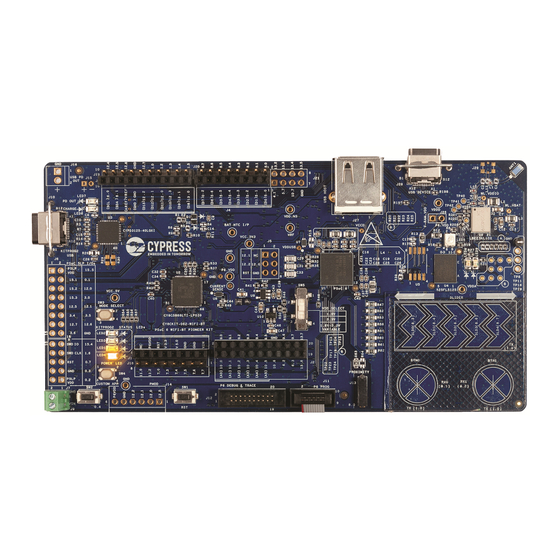
- Page 40 Kit Hardware The CY8CKIT-062-WiFi-BT Pioneer Kit comes with the PSoC 6 WiFi-BT Pioneer board, which has the CY8CKIT-028-TFT display shield connected, as Figure 4-3 shows. Figure 4-3. PSoC 6 WiFi-BT Pioneer Board and TFT Display Shield Figure 4-4 shows the markup of the Pioneer board. Figure 4-4.
- Page 41 56 for more details. 4. Cypress EZ-PD CCG3 Type-C Port Controller with PD (CYPD3125-40LQXIT, U3): The Pioneer board includes an EZ-PD CCG3 USB Type-C port controller with power delivery system. This device is pre-programmed and can deliver power from a Type-C port to an onboard header J16, while simultaneously charging a lithium-ion polymer battery connected to J15.
- Page 42 26. WiFi and Bluetooth module (LBEE5KL1DX-883, U6): This kit features the onboard WiFi and Bluetooth combination module to demonstrate the IoT features. The LBEE5KL1DX is a Type 1DX module available with 2.4-GHz WLAN and Bluetooth functionality. Based on Cypress CYW4343W, this module provides high-efficiency RF front-end circuits.
- Page 43 Pioneer Kit can also be connected between this USB connector and the PC to use the PSoC 6 MCU USB device applications. 31. Cypress PSoC 6 MCU (CY8C6247BZI-D54, U1): This kit is designed to highlight the features of the PSoC 6 MCU. For details on PSoC 6 MCU pin mapping, see Table 4-2 on page 45.
- Page 44 Kit Hardware Figure 4-5 shows the pinout of the Pioneer board. Figure 4-5. Pioneer Board Pinout PSoC® 6 WiFi-BT Pioneer Kit Guide, Document Number. 002-22677 Rev. *E...
- Page 45 Kit Hardware Table 4-2. Pioneer Board Pinout PSoC 6 Primary Secondary Connection Details Onboard Function Onboard Function XRES Reset – P0.0 WCO IN – P0.1 WCO OUT – P0.2 Arduino header J4.8, D7 – P0.3 RGB red LED – User button with Hibernate P0.4 –...
- Page 46 Kit Hardware Table 4-2. Pioneer Board Pinout (continued) PSoC 6 Primary Secondary Connection Details Onboard Function Onboard Function P3.4 BT REG ON – BT REG ON pin of the WiFi/BT module P3.5 BT HOST WAKE – BT HOST WAKE pin of the WiFi/BT module P4.0 BT DEV WAKE –...
- Page 47 Kit Hardware Table 4-2. Pioneer Board Pinout (continued) PSoC 6 Primary Secondary Connection Details Onboard Function Onboard Function GPIO on non- P7.4 TRACEDATA[3] Arduino header Populate R178 to connect to J18. (J18.4) GPIO on non- P7.5 TRACEDATA[2] Arduino header Populate R179 to connect to J18. (J18.3) GPIO on non- P7.6...
- Page 48 Kit Hardware Table 4-2. Pioneer Board Pinout (continued) PSoC 6 Primary Secondary Connection Details Onboard Function Onboard Function GPIO on non-Arduino P9.5 – header (J2.12) GPIO on non-Arduino P9.6 – header (J2.16) GPIO on non-Arduino P9.7 – header (J2.18) GPIO on Arduino header P10.0 –...
- Page 49 Kit Hardware Table 4-2. Pioneer Board Pinout (continued) PSoC 6 Primary Secondary Connection Details Onboard Function Onboard Function ICSP header (J5.3) Arduino J3.6, D13 Remove R81 to disconnect from KitProg2_SPI P12.2 and Pmod header SPI CLK lines. (J14.4) GPIO on non- Connected to primary function by default.
-
Page 50: Cy8Ckit-028-Tft Details
Kit Hardware CY8CKIT-028-TFT Details 4.2.1 CY8CKIT-028-TFT Display Shield Figure 4-6. TFT Display Shield The TFT display shield has the following peripherals: 1. 2.4-inch TFT display: This is a Newhaven 2.4-inch TFT LCD module with 240x320 pixel resolu- tion and uses a Sitronix ST7789 display controller. - Page 51 Kit Hardware Table 4-3. TFT Shield Pinout Arduino Pioneer Board Pin # Arduino Pin TFT Shield Function Function Connection J1.1 J1.2 J1.3 J1.4 J1.5 3.3 V 3.3 V VCC 3.3V 3.3 V J1.6 RESET RESET SWD RESET J1.7 I/O REF I/O REF VIO REF P6 VDD...
- Page 52 Kit Hardware Figure 4-7 shows the connectivity of the TFT display shield with the CY8CKIT-062-WiFi-BT base- board through the headers. Figure 4-7. TFT Shield Pinout Notes: The TFT display operation at 1.8 V is currently not supported in this version of the kit. Ensure the fol- lowing conditions are met when the CY8CKIT-028-TFT Display Shield is mounted on the PSoC 6 WiFi-BT Pioneer Board.
-
Page 53: Kitprog2
Kit Hardware KitProg2 4.3.1 Introduction The PSoC 6 WiFi-BT Pioneer Kit can be programmed and debugged using the onboard KitProg2. The KitProg2 is a multi-functional system, which includes a programmer, debugger, USB-I2C bridge, USB-UART bridge, and USB-SPI bridge. KitProg2 also supports mass storage programming and CMSIS-DAP, and custom applications. -
Page 54: Usb-Uart Bridge
Kit Hardware To know whether the kit is successfully enumerated, open PSoC Programmer software and connect the kit to your PC. Check the status of the onboard LEDs and the Port Selection window in PSoC Programmer to know the KitProg2 programming interface, see Figure 4-8 Figure 4-9. -
Page 55: Usb-I2C Bridge
Kit Hardware 4.3.5 USB-I2C Bridge The KitProg2 can function as a USB-I2C bridge and communicate with the Bridge Control Panel (BCP) software. The I2C lines on the PSoC 6 MCU are hard-wired on the board to the I2C lines of the KitProg2, with onboard pull-up resistors as Figure 4-11 shows. -
Page 56: Ez-Pd Ccg3 Type-C Power Delivery
Kit Hardware EZ-PD CCG3 Type-C Power Delivery The Pioneer board includes a Cypress EZ-PD CCG3 power delivery system. The EZ-PD CCG3 is pre-programmed and can deliver power from a Type-C port to the onboard header J16 (known as the consumer path), while simultaneously charging a 3.7-V, lithium-ion polymer battery connected to J15. - Page 57 Kit Hardware The power delivery system works as follows: 1. If the power delivery system detects a non Type-C power adapter (legacy USB), CCG3 will charge the battery at 100 mA. CCG3 will also disable the consumer and provider paths. 2.
-
Page 58: Appendix
A.2.1 PSoC 6 MCU (U1) PSoC 6 MCU is Cypress’ latest, ultra-low-power PSoC specifically designed for wearables and IoT products. It is a programmable embedded system-on-chip, integrating a 150-MHz CM4 as the primary application processor, a 100-MHz CM0+ that supports low-power operations, up to 1 MB Flash and 28 8KB SRAM, CapSense touch-sensing, and custom analog and digital peripheral functions. -
Page 59: Serial Interconnection Between Psoc 5Lp And Psoc 6 Mcu
A.2.3 Serial Interconnection between PSoC 5LP and PSoC 6 MCU In addition to being used as an onboard programmer, the PSoC 5LP functions as an interface for the USB-UART, USB-I2C, and USB-SPI bridges, as shown in Figure A-1. The USB-Serial pins of the PSoC 5LP are hard-wired to the I2C/UART/SPI pins of the PSoC 6 MCU. -
Page 60: Ez-Pd Ccg3 Power Delivery System
A.2.4 EZ-PD CCG3 Power Delivery System Cypress EZ-PD CCG3 provides a complete solution ideal for power adapters, power banks, Type-C dongles, monitors, docks, and notebooks. See EZ-PD CCG3 Type-C Power Delivery on page 56 more details of the power delivery system implementation on the Pioneer board. -
Page 61: Power Supply System
Figure A-3. EZ-PD CCG3 Power Delivery Setup using Two CY8CKIT-062-WiFi-BT Kits A.2.5 Power Supply System The power supply system on this board is versatile, allowing the input supply to come from the fol- lowing sources: 5 V, 9 V, or 12 V from the onboard USB Type-C connector ■... - Page 62 Table A-1 details the different powering scenarios for Pioneer board. Table A-1. Power Supply Scenarios Power Inputs Board Condition JTAG/SWD Main ETM Header Battery PSoC Battery Header Regulator (VTARG_IN) Connected Powered by Charging (VTARG_REF) Powered by Non Type-C power adapter Main <5 Type-C...
- Page 63 Figure A-4. Schematics of Power Supply System PSoC® 6 WiFi-BT Pioneer Kit Guide, Document Number. 002-22677 Rev. *E...
-
Page 64: Expansion Connectors
A.2.6 Expansion Connectors A.2.6.1 Arduino-compatible Headers (J1, J2, J3, J4, and J5) The board has five Arduino-compatible headers: J1, J2, J3, J4, and J5 (J5 is not populated by default). You can connect 3.3-V Arduino-compatible shields to develop applications based on the shield’s hardware. -
Page 65: Capsense Circuit
A.2.7 CapSense Circuit A CapSense slider and two buttons, all of which support both self-capacitance (CSD) and mutual- capacitance (CSX) sensing, and a CSD proximity sensor (header) are connected to PSoC 6 MCU as Figure A-5 shows. Four external capacitors – C and C for CSD, C and C... -
Page 66: Push Buttons
A.2.10 Cypress NOR Flash The Pioneer board has a Cypress NOR flash memory (S25FL512SAGMFI011) of 512 Mb capacity. The NOR flash is connected to the serial memory interface (SMIF) of PSoC 6 MCU. The NOR flash device can be used for both data and code memory with execute-in-place (XIP) support and encryption. -
Page 67: Wifi And Bluetooth Module
The Pioneer board features an onboard WiFi and Bluetooth combination module to demonstrate the wireless communication features. This LBEE5KL1DX is a Type 1DX module available with 2.4-GHz WLAN and Bluetooth functionality. Based on Cypress CYW4343W, this module provides high-effi- ciency RF front-end circuits. -
Page 68: Usb Host And Usb Device Connections
A.2.12 USB Host and USB Device Connections The PSoC 6 MCU can be configured as either a USB host or USB device. When PSoC 6 is pro- grammed as a host controller, you can connect an external device such as mouse, keyboard, and flash memory to the USB Type-A receptacle port (J27). -
Page 69: Psoc 6 Wifi-Bt Pioneer Board Reworks
PSoC 6 WiFi-BT Pioneer Board Reworks A.3.1 Bypass Protection Circuit on Program and Debug Header (J11) The 10-pin header allows you to program and debug PSoC 6 MCU using an external programmer such as MiniProg3. This header has a protection circuit that cuts-off any voltage greater that 3.4 V on VTARG_REF pin. -
Page 70: Psoc 6 Mcu User Button (Sw2)
Notes: 1. If you are programming the PSoC 6 MCU using a MiniProg3 connected to J11, make sure the voltage is set at either 2.5 V or at 3.3 V. 2. If you want to program the PSoC 6 MCU using MiniProg3 at the 1.8 V condition, make sure you are populating the 0-ohm resistor R196 on the board. -
Page 71: Capsense Shield
A.3.4 CapSense Shield The hatched pattern around the CapSense buttons and slider are connected to ground. If liquid toler- ance is required, this pattern needs to be connected to the shield pin. This pattern can be connected to either of the two ports P6.3 or P13.6 populated by R138 or R137, respectively. In both cases, resistor R44 connecting the hatched pattern to ground needs to be removed. -
Page 72: Lipo Battery Charger
A.3.6 LiPo Battery Charger Battery connector (J15) for lithium-ion polymer battery charger is not loaded by default; this need to be populated to evaluate battery charging and battery powering option. See the BOM for the recom- mended part numbers. Recommended lithium-ion polymer rate is 3.7 V at 850 mAH or higher. SparkFun Electronics PRT-13854 or equivalent. -
Page 73: Wiced Configuration
WICED Configuration This section describes the parts of the PSoC 6 MCU that are configured by WICED Studio 6.1. This section includes the following tables: Items that should not be changed ■ Items that should be changed with extreme caution ■... - Page 74 DMAs Priority Used For DW0_0 SDIO DW0_2 SDIO DW1_1 SDIO. Must be highest priority DMA in system DW1_3 SDIO. Must be highest priority DMA in system Do not create another DMA channel that will block DW1_1 or DW1_3 for a long period. All other channels must be of lower priority and preemptable.
- Page 75 Frequency: 50 Input: IMO Clk_Hf[0] root and See Clk_Hf[0] and Clk_HF[2] Output: 100 MHz Clk_Hf[2] Note: If you desire to change these configurations, contact Cypress technical support. PSoC® 6 WiFi-BT Pioneer Kit Guide, Document Number. 002-22677 Rev. *E...
- Page 76 Default configurations in WICED configured; these can be changed if needed. System Clocks Name Configuration Used For Notes The WICED audio API assume this clock Input: Clk_path_1 (PLL) Clocking audio sub- is configured for 90 MHz. If not using Clk_Hf[1] Divider: 1 system WICED audio API feel free to change.
- Page 77 Interrupts Name Number Priority Notes If not using WICED audio API, feel free to PDM Interrupt change. If using WICED audio API do not change. If not using WICED audio API, feel free to I2S Interrupt change. If using WICED audio API do not change.
- Page 78 Table A-2. WICED Names and their Configuration and Mapping in PSoC 6 WICED Name PSoC Resource and Configuration Notes Consumes SCB[6] Consumes 16 bit divider #6 MOSI - P12.0 WICED_SPI_7 MISO - P12.1 SCLK - P12.2 SS - P12.3 Consumes SCB[3] Consumes 16 bit divider #3 WICED_I2C_4 SCL - P6.0...
-
Page 79: Frequently Asked Questions
13.How can I evaluate the USB Type-C provider and consumer features to get started? 14.I am unable to program the target device. 15.Does the kit get powered when I power it from another Cypress kit through the J1 header? 16.What additional overlays can be used with CapSense? 17.What is Pmod? - Page 80 1. I don’t have a Type- C connector on my PC. Can I still connect and use this kit? Yes. To evaluate PSoC 6 MCU features, any PC with USB 2.0 connectivity is sufficient. A Type-C power adapter is required only to evaluate the CCG3 section of the kit. 2.
- Page 81 5 V/9 V/12 V device that has a current requirement of less that 1 A may be used. Additionally, Cypress has its own USB Type-C evaluation kit, which can be used to evaluate the provider and consumer features and many more. Visit www.cypress.com/products/usb-type-c-...
- Page 82 Ensure that the device used in PSoC Creator is CY8C6247BZI-D54. 15. Is it possible to power the kit from another Cypress kit through the J1 header? Yes, VIN pin on the J1 header is the supply input/output pin and can support up to 12 V.
- Page 83 20.Why am I not able to program PSoC 6 MCU using MiniProg3 at 1.8 V? The "Program/Debug Overvoltage Protection" circuit shown in A.3.1 Bypass Protection Circuit on Program and Debug Header (J11) on page 69 does not allow programming of the device at 1.8 V through MiniProg3.
-
Page 84: Revision History
TAVA Updated Appendix chapter on page Updated “Hardware Functional Description” on page Updated “Push Buttons” on page Updated description. Updated “Cypress NOR Flash” on page Added image. Updated “Frequently Asked Questions” on page Updated description. 6402445 12/05/2018 SRDS Updated PSoC Creator chapter on page Updated “Kit Code Examples”...
Need help?
Do you have a question about the PSoC CY8CKIT-062-WiFi-BT and is the answer not in the manual?
Questions and answers