
Related Manuals for Cypress PSoC 4 Pioneer Kit


Summary of Contents for Cypress PSoC 4 Pioneer Kit
- Page 1 CY8CKIT-042 ® PSoC 4 Pioneer Kit Guide Doc. # 001-86371 Rev. *D Cypress Semiconductor 198 Champion Court San Jose, CA 95134-1709 Phone (USA): 800.858.1810 Phone (Intnl): +1.408.943.2600 http://www.cypress.com...
- Page 2 Cypress Source Code and derivative works for the sole purpose of creating custom soft- ware and or firmware in support of licensee product to be used only in conjunction with a Cypress integrated circuit as speci- fied in the applicable agreement.
-
Page 3: Table Of Contents
4.3.5 Arduino Compatible Headers (J1, J2, J3, J4, and J12 - unpopulated)...36 4.3.6 Digilent Pmod Compatible Header (J5 - unpopulated)........38 4.3.7 PSoC 5LP GPIO Header (J8) ................39 4.3.8 CapSense Slider ....................40 4.3.9 Pioneer Board LEDs ..................41 4.3.10 Push Buttons....................42 CY8CKIT-042 PSoC 4 Pioneer Kit Guide, Doc. # 001-86371 Rev. *D... - Page 4 Pin Assignment Table....................104 Program and Debug Headers..................106 Use of Zero-ohm Resistors and No Load ..............107 Error in Firmware/Status Indication in Status LED ..........107 Bill of Materials (BOM).....................108 Regulatory Compliance Information ................110 CY8CKIT-042 PSoC 4 Pioneer Kit Guide, Doc. # 001-86371 Rev. *D...
-
Page 5: Safety Information
End-of-Life/Product Recycling This kit has an end-of-life cycle five years from the date of manufacturing mentioned on the back of the box. Contact your nearest recycler for discarding the kit. CY8CKIT-042 PSoC 4 Pioneer Kit Guide, Doc. # 001-86371 Rev. *D... - Page 6 General Safety Instructions ESD Protection ESD can damage boards and associated components. Cypress recommends that the user perform procedures only at an ESD workstation. If an ESD workstation is not available, use appropriate ESD protection by wearing an antistatic wrist strap attached to the chassis ground (any unpainted metal surface) on the board when handling parts.
-
Page 7: Introduction
5 V or 3.3 V as power supply voltages. The PSoC 4 Pioneer Kit is based on the PSoC 4200 device family, delivering a programmable platform for a wide range of embedded applications. The PSoC 4 is a scalable and reconfigurable platform architecture for a family of mixed-signal programmable embedded system controllers with ®... - Page 8 Introduction Figure 1-1. Kit Contents Inspect the contents of the kit; if you find any part missing, contact your nearest Cypress sales office for help: www.cypress.com/go/support. CY8CKIT-042 PSoC 4 Pioneer Kit Guide, Doc. # 001-86371 Rev. *D...
-
Page 9: Psoc Creator
PSoC devices. For more information, visit www.cypress.com/Creator. Getting Started This guide helps you to get acquainted with the PSoC 4 Pioneer Kit. The Software Installation chapter on page 11 describes the installation of the kit software. The... -
Page 10: Document Revision History
Click the File icon and then click Open. Displays an equation: Times New Roman 2 + 2 = 4 Text in gray boxes Describes cautions or unique functionality of the product. CY8CKIT-042 PSoC 4 Pioneer Kit Guide, Doc. # 001-86371 Rev. *D... -
Page 11: Software Installation
Install Kit Software Follow these steps to install the PSoC 4 Pioneer Kit software: 1. Download and install the PSoC 4 Pioneer Kit software from www.cypress.com/go/CY8CKIT-042. 2. Select the folder to install the CY8CKIT-042 related files. Choose the directory and click Next. -
Page 12: Install Hardware
There is no additional hardware installation required for this kit. Install Software When installing the PSoC 4 Pioneer Kit, the installer checks if the required software is installed in the system. If the required applications are not installed, then the installer prompts you to download and install them. -
Page 13: Uninstall Software
Software Installation Uninstall Software The software can be uninstalled using one of the following methods: Go to Start > All Programs > Cypress > Cypress Update Manager > Cypress Update Man- ■ ager; select the Uninstall button. Go to Start > Control Panel > Programs and Features; select the Uninstall/Change button. - Page 14 In addition to the example projects and starter designs that are available within PSoC Creator, Cypress continuously strives to provide the best support. Click here to view a growing list of applica- tion notes for PSoC 3, PSoC 4, and PSoC 5LP. CY8CKIT-042 PSoC 4 Pioneer Kit Guide, Doc. # 001-86371 Rev. *D...
-
Page 15: Open An Example Project In Psoc Creator
Figure 2-5. PSoC Creator Start Page 2. Open the example project from the Start Page by clicking <Project.cywrk> present below the Examples and Kits > Kits > CY8CKIT-042. Figure 2-6. Open Example Project CY8CKIT-042 PSoC 4 Pioneer Kit Guide, Doc. # 001-86371 Rev. *D... - Page 16 3. The example project opens and displays the project files in the Workspace Explorer. Subsequent sections of this user guide describe how to build, program, and understand the example projects supported in this kit. Figure 2-7. Workspace Explorer CY8CKIT-042 PSoC 4 Pioneer Kit Guide, Doc. # 001-86371 Rev. *D...
-
Page 17: Kit Operation
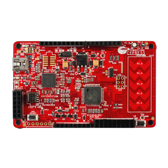
Kit Operation The PSoC 4 Pioneer Kit can be used to develop applications using the PSoC 4 family of devices and the Arduino shields and Digilent Pmod daughter cards. Figure 3-1 is an image of the PSoC 4 Pioneer board with a markup of the onboard components. -
Page 18: Pioneer Kit Usb Connection
Kit Operation Pioneer Kit USB Connection The PSoC 4 Pioneer Kit connects to the PC over a USB interface. The kit enumerates as a composite device and three separate devices appear under the Device Manager window in the Windows operating system. -
Page 19: Programming And Debugging Psoc 4
Figure 3-5 for this implementation. Figure 3-5. SWD Programming PSoC 4 Using PSoC 5LP SWDCLK P2[1] P3[2] Mini P15[6] SWDIO PSoC 5LP PSoC 4 P2[0] P3[3] P15[7] Reset P2[4] XRES CY8CKIT-042 PSoC 4 Pioneer Kit Guide, Doc. # 001-86371 Rev. *D... - Page 20 USB (VBUS) or by an external source such as an Arduino shield. If the board is already powered from another source, plugging in the USB programmer does not damage the board. CY8CKIT-042 PSoC 4 Pioneer Kit Guide, Doc. # 001-86371 Rev. *D...
-
Page 21: Using Cy8Ckit-002 Miniprog3 Programmer And Debugger
Options window, expand Program and Debug > Port Configuration; click MiniProg3 and select the settings shown in Figure 3-9. Click Debug > Program to program and power the board. Note The CY8CKIT-002 MiniProg3 is not part of the PSoC 4 Pioneer Kit contents. It can be purchased from the Cypress Online Store. -
Page 22: Usb-Uart Bridge
PSoC 4 device to the PC via the COM terminal software. When the USB mini-B cable is connected to J10 of the PSoC 4 Pioneer Kit, a device named KitProg USBUART is available under Ports (COM & LPT) in the device manager. For more details about the USB-UART functionality, see... - Page 23 1200, 2400, 4800, 9600, 19200, 38400, 57600, and 115200 Data Bits Parity None Stop Bits Flow Control None File transfer protocols Xmodem, 1K Xmodem, Ymodem, Kermit, and Zmodem (only speeds greater supported than 2400 baud). CY8CKIT-042 PSoC 4 Pioneer Kit Guide, Doc. # 001-86371 Rev. *D...
-
Page 24: Usb-I2C Bridge
Ports in the BCP. Figure 3-11. Bridge Control Panel To use the USB_I2C functionality, select the KitProg USB-I2C in the BCP. On successful connection, the Connected and Powered tabs turn green. CY8CKIT-042 PSoC 4 Pioneer Kit Guide, Doc. # 001-86371 Rev. *D... -
Page 25: Updating The Onboard Programmer Firmware
107), PSoC Programmer displays a warning indicating that new firmware is available. Open PSoC Programmer from Start > All Programs > Cypress > PSoC Programmer<version>. When PSoC Programmer opens, a WARNING! window pops up saying that the programmer is currently out of date. - Page 26 Click the Utilities tab and click the Upgrade Firmware button. On successful upgrade, the Action and Results window displays the firmware update message with the KitProg version. Figure 3-15. Firmware Updated in PSoC Programmer CY8CKIT-042 PSoC 4 Pioneer Kit Guide, Doc. # 001-86371 Rev. *D...
-
Page 27: Hardware
CapSense VIN (J11) Slider PSoC 4 Additional Program Header (J6) PSoC 5LP I/O Header (J8) PSoC 4 Reset Button Arduino Digilent Pmod PSoC 5LP Arduino PSoC 4 User Compatible Compatible Programmer Compatible 44 TQFP Button I/O Header I/O Header (J5) and I/O Header (J1) Debugger (J2) CY8CKIT-042 PSoC 4 Pioneer Kit Guide, Doc. # 001-86371 Rev. *D... - Page 28 I/O Header (J4) A3/P2_3 P1_5 Compatible P0_7/D2 I/O Header (J2) A4/P2_4 P1_4 P0_5/D1 A5/P2_5 P1_3 P0_4/D0 P0_0 P0_1 P1_2 P1_0 P1_1 PSoC 4 Pioneer Kit Digilent Pmod Arduino UNO CY8CKIT-042 PSoC 4 Pioneer Kit Guide, Doc. # 001-86371 Rev. *D...
-
Page 29: Theory Of Operation
J8 to enable using the onboard PSoC 5LP to develop custom applications. The PSoC 4 Pioneer Kit can be powered from the USB Mini B, the Arduino compatible header, or an external power supply. The input voltage is regulated by a low drop-out (LDO) regulator to 3.3 V. You can select between VBUS (5 V) and 3.3 V by suitably plugging the jumper onto the voltage selection... -
Page 30: Functional Description
Drive modes, strengths, and slew rates are programmable ❐ PSoC Creator design environment ■ Integrated development environment (IDE) provides schematic design entry and build (with ❐ analog and digital automatic routing) CY8CKIT-042 PSoC 4 Pioneer Kit Guide, Doc. # 001-86371 Rev. *D... -
Page 31: Psoc 5Lp
20 to 24 programmable logic device (PLD) based universal digital blocks (UDBs) ❐ Full CAN 2.0b 16 RX, 8 TX buffers ❐ Full-Speed (FS) USB 2.0 12 Mbps using internal oscillator CY8CKIT-042 PSoC 4 Pioneer Kit Guide, Doc. # 001-86371 Rev. *D... - Page 32 Internal PLL clock generation up to 67 MHz ❐ 32.768-kHz watch crystal oscillator ❐ Low-power internal oscillator at 1, 33, and 100 kHz ❐ For more, see the CY8C58LPxx family datasheet. CY8CKIT-042 PSoC 4 Pioneer Kit Guide, Doc. # 001-86371 Rev. *D...
-
Page 33: Power Supply System
Note: The 5-V domain is directly powered by the USB (VBUS). For this reason, this domain is unregulated. Figure 4-4. Power Supply Block Diagram with Protection Circuits I/O Header 3.3V MOSFET based Protection Ckt PSoC 4 PSoC 5LP P4 10pin P5LP 10pin P5LP I/O Protection Debug Debug Header CY8CKIT-042 PSoC 4 Pioneer Kit Guide, Doc. # 001-86371 Rev. *D... - Page 34 Remove jumper J13. Connect the positive terminal of voltage supply to the positive terminal of ❐ the ammeter and the negative terminal of the ammeter to the lower pin of J13. Figure 4-6 shows the required connections. CY8CKIT-042 PSoC 4 Pioneer Kit Guide, Doc. # 001-86371 Rev. *D...
-
Page 35: Programming Interface
The kit allows programming and debugging of the PSoC 4 in two modes: ■ Using the Onboard PSoC 5LP Programmer and Debugger Using CY8CKIT-002 MiniProg3 Programmer and Debugger ■ CY8CKIT-042 PSoC 4 Pioneer Kit Guide, Doc. # 001-86371 Rev. *D... -
Page 36: Arduino Compatible Headers (J1, J2, J3, J4, And J12 - Unpopulated)
Arduino ICSP compatible header for the SPI interface. This header is not populated. Refer to the “No Load Components” section of A.6 Bill of Materials (BOM) on page 108 for the header part number. CY8CKIT-042 PSoC 4 Pioneer Kit Guide, Doc. # 001-86371 Rev. *D... - Page 37 PSoC 4 are brought to this header. The port 1 pins additionally connect to the onboard CapSense slider through 560- resistors. When the CapSense feature is not used, remove these resistors to ensure a better performance with these pins. CY8CKIT-042 PSoC 4 Pioneer Kit Guide, Doc. # 001-86371 Rev. *D...
-
Page 38: Digilent Pmod Compatible Header (J5 - Unpopulated)
The J12 header is a 2×3 header that supports Arduino shields. This header is used on a small subset of shields and is unpopulated on the PSoC 4 Pioneer Kit. Note that the J12 header only functions in 5.0 V mode. To ensure proper shield functionality, ensure the power jumper is connected in 5.0 V mode. -
Page 39: Psoc 5Lp Gpio Header (J8)
Table on page 104 for pin details. Figure 4-12. PSoC 5LP GPIO Header (J8) P5LP_VDD P5LP1_2 P5LP0_0 P5LP0_1 P5LP3_4 P5LP3_5 P5LP3_6 P5LP3_7 P5LP12_6 P5LP12_7 P5LP3_0 6x2 RECPT PSoC 5LP GPIO Extension Header CY8CKIT-042 PSoC 4 Pioneer Kit Guide, Doc. # 001-86371 Rev. *D... -
Page 40: Capsense Slider
This shield must be connected to a designated shield pin on the device to function. The shield must be connected to the ground when not used. On the PSoC 4 Pioneer Kit, the connection of the shield to the pin or to the ground is made by resistors R44 and R45, respectively. By default, R45 is mounted on the board, which connects the shield to the ground. -
Page 41: Pioneer Board Leds
Figure 4-16. Status LED and Power LED P5LP_VDD R3 560 ohm P5LP3_1 0805 0805 330 ohm Status LED Green Power LED Figure 4-17. RGB LED 2.2K 1.5K P1_6 P0_2 P4_VDD 1.5K P0_3 RGB LED CY8CKIT-042 PSoC 4 Pioneer Kit Guide, Doc. # 001-86371 Rev. *D... -
Page 42: Push Buttons
The User button is connected to P0[7] of PSoC 4 device. Both the push buttons connect to ground on activation (active low). Figure 4-18. Push Buttons /XRES EVQ-PE105K RESET P0_7 EVQ-PE105K USER BUTTON CY8CKIT-042 PSoC 4 Pioneer Kit Guide, Doc. # 001-86371 Rev. *D... -
Page 43: Code Examples
2. Open the code example by clicking <Project.cywrk> below Examples and Kits > Find Exam- ple Project > Kits > CY8CKIT-042. Figure 5-1. Open Code Example from PSoC Creator CY8CKIT-042 PSoC 4 Pioneer Kit Guide, Doc. # 001-86371 Rev. *D... - Page 44 6. If the device is not yet acquired, PSoC Creator will open the programming window. Select KitProg/ and click the Port Acquire button. Figure 5-4. Acquire Device from PSoC Creator CY8CKIT-042 PSoC 4 Pioneer Kit Guide, Doc. # 001-86371 Rev. *D...
- Page 45 7. After the device is acquired, it is shown in a tree structure below the KitProg. Now, click the Connect button. Figure 5-5. Connect Device from PSoC Creator 8. Click OK to exit the window and start programming. Figure 5-6. Program Device from PSoC Creator CY8CKIT-042 PSoC 4 Pioneer Kit Guide, Doc. # 001-86371 Rev. *D...
-
Page 46: Project: Blinking Led
50 percent. The blinking frequency and duty cycle can be varied by varying the period and compare value respectively. Note: The PSoC 4 Pioneer Kit is factory-programmed with this example. Figure 5-7. PSoC Creator Schematic Design of Blinking LED Project 5.1.2... -
Page 47: Flow Chart
LED. Change the period and compare value in the PWM component, as shown in Figure 5-10. Rebuild and reprogram the device to vary the frequency and duty cycle. CY8CKIT-042 PSoC 4 Pioneer Kit Guide, Doc. # 001-86371 Rev. *D... - Page 48 Code Examples Figure 5-10. PWM Component Configuration Window CY8CKIT-042 PSoC 4 Pioneer Kit Guide, Doc. # 001-86371 Rev. *D...
-
Page 49: Project: Pwm
Open PWM.cydwr in the Workspace Explorer and select the suitable pins. Table 5-2. Pin Connections Pin Name Port Name PWM1 P1_6 (Red) PWM2 P0_2 (Green) PWM3 P0_3 (Blue) CY8CKIT-042 PSoC 4 Pioneer Kit Guide, Doc. # 001-86371 Rev. *D... -
Page 50: Flow Chart
Code Examples Figure 5-12. Pin Selection for PWM Project 5.2.3 Flow Chart Figure 5-13 shows the flow chart of code implemented in main.c. Figure 5-13. PWM Project Flow Chart CY8CKIT-042 PSoC 4 Pioneer Kit Guide, Doc. # 001-86371 Rev. *D... -
Page 51: Verify Output
4.3.3.2 Procedure to Measure PSoC 4 Current Consumption on page Open Deep Sleep.cydwr in the Workspace Explorer and select the suitable pin. Table 5-3. Pin Connection Pin Name Port Name P1_6 (Red) Switch P0_7 CY8CKIT-042 PSoC 4 Pioneer Kit Guide, Doc. # 001-86371 Rev. *D... -
Page 52: Flow Chart
Figure 5-16. Deep-Sleep Project Flow Chart Start Turn LED on for one second Enter Deep- Sleep mode Interrupt on SW2 press Clear the interrupt CY8CKIT-042 PSoC 4 Pioneer Kit Guide, Doc. # 001-86371 Rev. *D... -
Page 53: Verify Output
This code example demonstrates CapSense on PSoC 4. The example uses the five-segment CapSense slider on the board. Each capacitive sensor on the slider is scanned using Cypress’s CapSense Sigma Delta (CSD) algorithm implemented in the CapSense component. This project is pre-tuned to take care of the board parasitics. - Page 54 P1_6 (Red) and P0_2 (Green) I2C communication lines P3_0 (SCL) and P3_1 (SDA) Note: The I2C communication lines are not used when tuning is disabled. Figure 5-18. Pin Selection for CapSense Project CY8CKIT-042 PSoC 4 Pioneer Kit Guide, Doc. # 001-86371 Rev. *D...
-
Page 55: Capsense (With Tuning)
The code example uses the five-segment CapSense slider on the board. Each capacitive sensor on the slider is scanned using Cypress's CapSense Sigma Delta (CSD) algorithm implemented in the CapSense component. The code uses tuner APIs. The tuner API CapSense_TunerComm() is used in the main loop to scan sensors, which also sends the CapSense variables RawCounts, Baseline, and Difference Counts (Signal) to the PC GUI through I2C communication. - Page 56 Initialise and start the PWM and CapSense Tuner Start Tuner communication Get the finger position on the slider Set the PWM output width to adjust the brightness of the RGB LED CY8CKIT-042 PSoC 4 Pioneer Kit Guide, Doc. # 001-86371 Rev. *D...
- Page 57 2. To open the tuner, right-click on the CapSense_CSD component in PSoC Creator and click Launch Tuner. Figure 5-22. Launch Tuner 3. The Tuner GUI opens. Click Configuration to open the configuration window. CY8CKIT-042 PSoC 4 Pioneer Kit Guide, Doc. # 001-86371 Rev. *D...
- Page 58 Code Examples Figure 5-23. Tuner GUI 4. Set the I2C communication parameters, as shown in the following figure. Figure 5-24. I2C Communication CY8CKIT-042 PSoC 4 Pioneer Kit Guide, Doc. # 001-86371 Rev. *D...
- Page 59 Code Examples 5. Click OK to apply the settings. 5.4.2.5 Verify Output 1. To start the scanning and communication process, click Start. Figure 5-25. Start Communication CY8CKIT-042 PSoC 4 Pioneer Kit Guide, Doc. # 001-86371 Rev. *D...
- Page 60 On/Off status for each sensor are represented as a graph. 4. Select the sensor parameters to observe, as shown in the following figure. The graph of the selected parameters is shown. CY8CKIT-042 PSoC 4 Pioneer Kit Guide, Doc. # 001-86371 Rev. *D...
- Page 61 Code Examples Figure 5-27. Sensor Parameter Graph CY8CKIT-042 PSoC 4 Pioneer Kit Guide, Doc. # 001-86371 Rev. *D...
- Page 62 Code Examples 5. Touch a sensor or slider element and see the increase in raw counts. Figure 5-28. Raw Count Increase CY8CKIT-042 PSoC 4 Pioneer Kit Guide, Doc. # 001-86371 Rev. *D...
-
Page 63: Advanced Topics
1. Open a new PSoC 4 project in the PSoC Creator. Select an appropriate location for your project and rename the project as required. Figure 6-1. Opening New Project from PSoC Creator CY8CKIT-042 PSoC 4 Pioneer Kit Guide, Doc. # 001-86371 Rev. *D... - Page 64 2. Drag and drop a UART (SCB) component to the top design. Figure 6-2. UART Component Under Component Catalog 3. To configure the UART, double-click or right-click on the UART component and select Configure. Figure 6-3. Open UART Configuration Window CY8CKIT-042 PSoC 4 Pioneer Kit Guide, Doc. # 001-86371 Rev. *D...
- Page 65 Advanced Topics 4. Configure the UART as shown in the following figures. Figure 6-4. UART Configuration Window Figure 6-5. UART Basic Configuration Window CY8CKIT-042 PSoC 4 Pioneer Kit Guide, Doc. # 001-86371 Rev. *D...
- Page 66 Advanced Topics Figure 6-6. UART Advanced Configuration Window 5. Select P0[4] for UART RX and P0[5] for UART TX in the Pins tab of <Project.cydwr>. Figure 6-7. Pin Selection CY8CKIT-042 PSoC 4 Pioneer Kit Guide, Doc. # 001-86371 Rev. *D...
- Page 67 = UART_UartGetChar(); if(0u != ch) /* Send the data through UART. This functions is blocking and waits until there is an entry into the TX FIFO. */ UART_UartPutChar(ch); CY8CKIT-042 PSoC 4 Pioneer Kit Guide, Doc. # 001-86371 Rev. *D...
- Page 68 UART component. An SCB implementation of UART will route the RX and TX pins to either one of the following subsets: (P0[4], P0[5]) or (P3[0],P3[1]) or (P4[0],P4[1]). CY8CKIT-042 PSoC 4 Pioneer Kit Guide, Doc. # 001-86371 Rev. *D...
- Page 69 2. Open HyperTerminal and select File > New Connection and enter a name for the new connec- tion and click OK. For PuTTY, double click the putty icon and select Serial under Connection. CY8CKIT-042 PSoC 4 Pioneer Kit Guide, Doc. # 001-86371 Rev. *D...
- Page 70 In HyperTerminal, select COMX (or the specific communication port that is assigned to KitProg USB-UART) in Connect using and click OK. In PuTTY enter the COMX in Serial line to connect to. This code example uses COM12. CY8CKIT-042 PSoC 4 Pioneer Kit Guide, Doc. # 001-86371 Rev. *D...
- Page 71 Make sure that the settings are identical to the UART settings configured for PSoC 4. In PuTTY select 'Speed (baud)', 'Data bits', 'Stop bits', 'Parity' and 'Flow control' under Configure the serial line. Click Session and select Serial under Connection type. CY8CKIT-042 PSoC 4 Pioneer Kit Guide, Doc. # 001-86371 Rev. *D...
- Page 72 Advanced Topics Serial line shows the communication port (COM12) and Speed shows the baud rate selected. Click Open to start the communication. Figure 6-13. Configure the Communication Port HyperTerminal PuTTY CY8CKIT-042 PSoC 4 Pioneer Kit Guide, Doc. # 001-86371 Rev. *D...
- Page 73 HyperTerminal. In PuTTY, enable the Force on under Terminal > Line discipline options to display the typed characters on the PuTTY. Figure 6-15. Enabling echo of typed characters in HyperTerminal CY8CKIT-042 PSoC 4 Pioneer Kit Guide, Doc. # 001-86371 Rev. *D...
- Page 74 Figure 6-16. Enabling echo of typed characters in PuTTY 6. The COM terminal software displays both the typed data and the looped back data from the PSoC 4 UART. Figure 6-17. Data Displayed on HyperTerminal CY8CKIT-042 PSoC 4 Pioneer Kit Guide, Doc. # 001-86371 Rev. *D...
- Page 75 Advanced Topics Figure 6-18. Data Displayed on PuTTY CY8CKIT-042 PSoC 4 Pioneer Kit Guide, Doc. # 001-86371 Rev. *D...
-
Page 76: Using Psoc 5Lp As Usb-I2C Bridge
The following steps describe how to use the USB-I2C bridge, which can communicate between the BCP and the PSoC 4. 1. Open a new project targeting the PSoC 4 device in PSoC Creator. Figure 6-19. Opening a New Project in PSoC Creator CY8CKIT-042 PSoC 4 Pioneer Kit Guide, Doc. # 001-86371 Rev. *D... - Page 77 Figure 6-20. I2C Component in Component Catalog 3. To configure the I2C component, double-click or right-click on the I2C component and select Configure. Figure 6-21. Open I2C Configuration Window CY8CKIT-042 PSoC 4 Pioneer Kit Guide, Doc. # 001-86371 Rev. *D...
- Page 78 Figure 6-22. I2C Configuration Tab Figure 6-23. I2C Tab 5. Select pin P3[0] for the I2C SCL and pin P3[1] for the I2C SDA in the Pins tab of <poject.cydwr>. CY8CKIT-042 PSoC 4 Pioneer Kit Guide, Doc. # 001-86371 Rev. *D...
- Page 79 /* Initialize write buffer */ I2C_I2CSlaveInitWriteBuf((uint8 *) wrBuf, 10); /* Initialize read buffer */ I2C_I2CSlaveInitReadBuf((uint8 *) rdBuf, 10); for(;;) /* Loop forever */ /* Wait for I2C master to complete a write */ CY8CKIT-042 PSoC 4 Pioneer Kit Guide, Doc. # 001-86371 Rev. *D...
- Page 80 ([Ctrl]+[F5]) this code onto the PSoC 4 through the PSoC 5LP pro- grammer or MiniProg3. 7. Open the BCP from Start > All Programs > Cypress > Bridge Control Panel <version num- ber>. 8. Connect to KitProg/ under Connected I2C/SPI/RX8 Ports.
- Page 81 Make sure the I2C speed is the same as the one configured in the I2C component. Click OK to close the window. Figure 6-26. Opening Protocol Configuration Window in BCP CY8CKIT-042 PSoC 4 Pioneer Kit Guide, Doc. # 001-86371 Rev. *D...
- Page 82 A '+' indication after each byte indicates that the transaction was successful and a '–' indicates that the transaction was a failure. Figure 6-27. Entering Commands in BCP CY8CKIT-042 PSoC 4 Pioneer Kit Guide, Doc. # 001-86371 Rev. *D...
- Page 83 Figure 6-29. Read Data Bytes from the BCP Note: Refer Help Contents under Help in BCP or press [F1] for details of I2C commands. CY8CKIT-042 PSoC 4 Pioneer Kit Guide, Doc. # 001-86371 Rev. *D...
-
Page 84: Developing Applications For Psoc 5Lp
Developing Applications for PSoC 5LP The PSoC 4 Pioneer Kit has an onboard PSoC 5LP whose primary function is that of a programmer and a bridge. You can build either a normal project or a bootloadable project using the PSoC 5LP. - Page 85 Advanced and select the Device as CY8C5868LTI-LP039, as shown in Figure 6-33. Select the Application Type as Bootloadable from the drop-down list. Figure 6-32. Opening New Project in PSoC Creator CY8CKIT-042 PSoC 4 Pioneer Kit Guide, Doc. # 001-86371 Rev. *D...
- Page 86 Figure 6-33. Selecting Device in PSoC Creator 2. Navigate to the Schematic view and drag and drop a bootloadable component on the top design. Figure 6-34. Bootloadable Component in Component Catalog CY8CKIT-042 PSoC 4 Pioneer Kit Guide, Doc. # 001-86371 Rev. *D...
- Page 87 Browse button. Select the KitProg_Bootloader.hex and KitProg_Bootloader.elf files; click Open. Figure 6-35. Configuration Window of Bootloadable Component Figure 6-36. Selecting KitProg Bootloader Hex File CY8CKIT-042 PSoC 4 Pioneer Kit Guide, Doc. # 001-86371 Rev. *D...
- Page 88 The KitProg_Bootloader.cydwr system settings is shown in the following figure. Figure 6-38. KitProg Bootloader System Settings 5. Build the project in PSoC Creator by selecting Build > Build Project or [Shift]+[F6]. CY8CKIT-042 PSoC 4 Pioneer Kit Guide, Doc. # 001-86371 Rev. *D...
- Page 89 7. In the Bootloader Host tool, click Filters and add a filter to identify the USB device. Set VID as 0x04B4, PID as 0xF13B, and click OK. Figure 6-40. Port Filters Tab in Bootloader Host Tool CY8CKIT-042 PSoC 4 Pioneer Kit Guide, Doc. # 001-86371 Rev. *D...
- Page 90 PSoC 4 (J13) is removed and subsequently the USB Mini- B connector is plugged into header J10. Figure 6-42. Selecting Bootloadable .cyacd File from Bootloader Host CY8CKIT-042 PSoC 4 Pioneer Kit Guide, Doc. # 001-86371 Rev. *D...
- Page 91 4. The status LED does not function unless used by the custom project. For additional information on bootloaders, refer to Cypress application note, AN73503 - USB HID Bootloader for PSoC 3 and PSoC 5LP. CY8CKIT-042 PSoC 4 Pioneer Kit Guide, Doc. # 001-86371 Rev. *D...
-
Page 92: Building A Normal Project For Psoc 5Lp
5. To program the PSoC 5LP with PSoC Creator, click Debug > Program or [Ctrl]+[F5]. The Pro- gramming window shows MiniProg3 and the selected device in the project under it (CY8C5868LTI-LP039). CY8CKIT-042 PSoC 4 Pioneer Kit Guide, Doc. # 001-86371 Rev. *D... -
Page 93: Psoc 5Lp Factory Program Restore Instructions
2. Configure the Pioneer Kit in Service Mode. To do this, while holding down the reset button (SW1 Reset), plug in the PSoC 4 Pioneer Kit to the computer using the included USB cable (USB A to mini-B). This puts the PSoC 5LP into service mode, which is indicated by the blinking green sta- tus LED. - Page 94 4. Switch to the Utilities tab in PSoC Programmer and press the Upgrade Firmware button. Unplug all other PSoC programmers (such as MiniProg3 and DVKProg) from the PC before pressing the Upgrade Firmware button. Figure 6-45. Upgrade Firmware CY8CKIT-042 PSoC 4 Pioneer Kit Guide, Doc. # 001-86371 Rev. *D...
- Page 95 Figure 6-46. Firmware Update Complete KitProg Version 2.03 6. The factory program is now successfully restored on the PSoC 5LP. It can be used as the pro- grammer/debugger for the PSoC 4 device. CY8CKIT-042 PSoC 4 Pioneer Kit Guide, Doc. # 001-86371 Rev. *D...
- Page 96 Restore PSoC 5LP Factory Program Using USB Host Tool 1. Launch the Bootloader Host tool from Start > Cypress > PSoC Creator. 2. Using the File > Open menu, load the Kit Prog.cyacd file, which is installed with the kit software.
- Page 97 3. Configure the Pioneer Kit in Service Mode. To do this, while holding down the reset button (SW1 Reset), plug in the PSoC 4 Pioneer Kit to the computer using the included USB cable (USB A to mini-B). This puts the PSoC 5LP into service mode, which is indicated by the blinking green sta- tus LED.
-
Page 98: Psoc 5Lp Is Programmed With A Standard Application
If PSoC 5LP is programmed with a standard application, restore the factory program by using the fol- lowing method. 1. Launch PSoC Programmer 3.18 or later from Start > Cypress > PSoC Programmer. 2. Use the File > Open menu to load the KitProg.hex factory program hex file, which is shipped with the kit. - Page 99 5. When ready, press the Program button (or File > Program) to program the PSoC 5LP device. 6. After programming has completed, the following message appears: “Program Finished at <time>”. CY8CKIT-042 PSoC 4 Pioneer Kit Guide, Doc. # 001-86371 Rev. *D...
- Page 100 Figure 6-51. Program Finished 7. The factory program is now successfully restored on the PSoC 5LP. It can be used as the pro- grammer/debugger for the PSoC 4 device. CY8CKIT-042 PSoC 4 Pioneer Kit Guide, Doc. # 001-86371 Rev. *D...
-
Page 101: Appendix
22 uFd 16v VBUS 0603 232 ohm 1.0 uF USB MINI B 100K VBUS R3 560 ohm V3.3 0805 C16 0.01 uF Power LED 2 PIN HDR NO LOAD CY8CKIT-042 PSoC 4 Pioneer Kit Guide, Doc. # 001-86371 Rev. *D... - Page 102 0.1 uF P5LP_TDI 0.1 uF P5LP2_3 R34 ZERO P5LP_XRES P5LP2_4 /XRES 50MIL KEYED SMD 50MIL KEYED SMD NO LOAD PSoC 5LP Program/Debug Header PSoC 4 / External PSoC Program/Debug Header CY8CKIT-042 PSoC 4 Pioneer Kit Guide, Doc. # 001-86371 Rev. *D...
- Page 103 P1_2 P1_0 P1_0 P1_1 P2_7 9x2 RECP 8x1 RECP (J1-J4) Arduino Compatible Headers NO LOAD R46 ZERO PMOS( DMP3098L-7) V3.3_EXT V3.3 442 ohm PMOS( DMP3098L-7) 1K ohm Protection Circuit CY8CKIT-042 PSoC 4 Pioneer Kit Guide, Doc. # 001-86371 Rev. *D...
-
Page 104: Pin Assignment Table
PSoC 4 Signal PSoC 4 Description J3_01 P2[6] J3_02 P3[6] D9(PWM) J3_03 P3[4] D10(PWM/SS) J3_04 P3[0] D11(PWM/MOSI) J3_05 P3[1] D12(MISO) J3_06 P0[6] D13(SCK) J3_07 J3_08 P1[7] AREF J3_09 P4[1] J3_10 P4[0] CY8CKIT-042 PSoC 4 Pioneer Kit Guide, Doc. # 001-86371 Rev. *D... - Page 105 Digilent Pmod Cards Support Header (J5) PSoC 4 Description Kit Signal (Default Pmod Signals) J5_01 P3[5] SPI_SS (multiplex with J4_06) J5_02 P3[0] SPI_MOSI J5_03 P3[1] SPI_MISO J5_04 P0[6] SPI_SCK J5_05 J5_06 CY8CKIT-042 PSoC 4 Pioneer Kit Guide, Doc. # 001-86371 Rev. *D...
-
Page 106: Program And Debug Headers
PSoC 5LP Direct Program/Debug Header (J7) PSoC 5LP PSoC 5LP Description Description Signal Signal J7_01 J7_02 P1[0] TMS/SWDIO J7_03 J7_04 P1[1] TCLK/SWCLK J7_05 J7_06 P1[3] TDO/SWO J7_07 J7_08 P1[4] J7_09 J7_10 XRES RESET CY8CKIT-042 PSoC 4 Pioneer Kit Guide, Doc. # 001-86371 Rev. *D... -
Page 107: Use Of Zero-Ohm Resistors And No Load
PSoC 5LP pro- successfully grammer. Note: LED status is not applicable when a custom project is running in PSoC 5LP. CY8CKIT-042 PSoC 4 Pioneer Kit Guide, Doc. # 001-86371 Rev. *D... -
Page 108: Bill Of Materials (Bom)
CONN HEADER FMAL 12PS.1" DL Sullins Connector 6x2 RECP PPPC062LFBN-RC GOLD Solutions CONN HEADER VERT SGL 3POS 3p_jumper 961103-6404-AR GOLD CONN USB MINI AB SMT RIGHT USB Mini B TE Connectivity 1734035-2 ANGLE CY8CKIT-042 PSoC 4 Pioneer Kit Guide, Doc. # 001-86371 Rev. *D... - Page 109 68QFN PSoC 5LP chip for USB debug Cypress Semicon- (CY8C5868L CY8C5868LTI-LP039 channel and USB-Serial interface ductor TI-LP039 ) No Load Components CAP CERAMIC 1.0UF 25V X5R 0603 1.0 uFd Taiyo Yuden TMK107BJ105KA-T CY8CKIT-042 PSoC 4 Pioneer Kit Guide, Doc. # 001-86371 Rev. *D...
-
Page 110: Regulatory Compliance Information
Cypress Semicon- Kit QR code ductor Regulatory Compliance Information The CY8CKIT-042 PSoC 4 Pioneer Kit has been tested and verified to comply with the following electromagnetic compatibility (EMC) regulations: EN 55022:2010 Class A - Emissions ■ EN 55024:2010 Class A - Immunity ■...
Need help?
Do you have a question about the PSoC 4 Pioneer Kit and is the answer not in the manual?
Questions and answers