
Related Manuals for Cypress CY8CKIT-040 PSoC 4000 Pioneer Kit


Summary of Contents for Cypress CY8CKIT-040 PSoC 4000 Pioneer Kit
- Page 1 CY8CKIT-040 ® PSoC 4000 Pioneer Kit Guide Doc. # 001-91316 Rev. *F Cypress Semiconductor 198 Champion Court San Jose, CA 95134-1709 www.cypress.com...
- Page 2 Cypress is not liable, in whole or in part, and you shall and hereby do release Cypress from any claim, damage, or other liability arising from or related to all Unintended Uses of Cypress products.
-
Page 3: Table Of Contents
Contents Safety Information 1. Introduction Kit Contents .........................7 PSoC Creator ......................9 1.2.1 PSoC Creator Code Examples ..............10 1.2.2 Kit Code Example ..................11 1.2.3 PSoC Creator Help ..................12 Getting Started......................13 Additional Learning Resources..................13 Technical Support......................14 Documentation Conventions..................14 2. Software Installation Before You Begin.......................15 Install Software ......................15 Install Hardware......................17 Uninstall Software......................18... - Page 4 Contents 5. Code Examples Overview........................49 5.1.1 Programming the Example Projects...............49 Project: Blinking LED ....................54 5.2.1 Project Overview ....................54 5.2.2 Project Description ..................55 5.2.3 Verify Output ....................56 Project: CapSense Proximity and UART ..............57 5.3.1 Project Overview ....................57 5.3.2 Project Description ..................58 5.3.3 Verify Output ....................67 Project: CapSense Touchpad with I2C Tuner ............74 5.4.1 Project Overview ....................74...
-
Page 5: Safety Information
Safety Information Regulatory Compliance ® The CY8CKIT-040 PSoC 4000 Pioneer Kit is intended for use as a development platform for hardware or software in a laboratory environment. The board is an open system design, which does not include a shielded enclosure. For this reason, the board may cause interference to other electrical or electronic devices in close proximity. - Page 6 General Safety Instructions ESD Protection ESD can damage boards and associated components. Cypress recommends that the user perform procedures only at an ESD workstation. If an ESD workstation is not available, use appropriate ESD protection by wearing an antistatic wrist strap attached to the chassis ground (any unpainted metal surface) on the board when handling parts.
-
Page 7: Introduction
Introduction ® Thank you for your interest in the PSoC 4000 Pioneer Kit. The kit is designed as an easy-to-use and inexpensive development kit, highlighting the unique flexibility of the PSoC 4000 architecture. Designed for flexibility, this kit offers footprint compatibility with several third-party Arduino™ shields. In addition, the board features an RGB LED, integrated USB programmer/debugger, a program/ ®... - Page 8 Introduction Figure 1-1. Kit Contents Inspect the contents of the kit; if you find any part missing, contact your nearest Cypress sales office for help: www.cypress.com/go/support. Download the latest version of the kit setup file from www.cypress.com/CY8CKIT-040. ® CY8CKIT-040 PSoC...
-
Page 9: Psoc Creator
Figure 1-2. PSoC Creator Features PSoC Creator also enables you to tap into an entire tool ecosystem with integrated compiler chains and production programming programmers for PSoC devices. For more information, visit www.cypress.com/psoccreator. Visit PSoC Creator training page for video tutorials on learning and using PSoC Creator. -
Page 10: Psoc Creator Code Examples
Introduction 1.2.1 PSoC Creator Code Examples PSoC Creator includes a large number of code examples. These examples are available from the PSoC Creator Start Page, as Figure 1-3 shows. Code examples can speed up your design process by starting you off with a complete design, instead of a blank page. -
Page 11: Kit Code Example
Introduction Figure 1-4. Code Example Projects with Sample Code 1.2.2 Kit Code Example In addition to the examples built into PSoC Creator, this kit includes a simple example, which can be used to quickly evaluate the functionality of this kit. The example is described in the Code Examples chapter on page 49. -
Page 12: Psoc Creator Help
Introduction 1.2.3 PSoC Creator Help Visit the PSoC Creator home page to download the latest version of PSoC Creator. Then, launch PSoC Creator and navigate to the following items: Quick Start Guide: Choose Help > Documentation > Quick Start Guide. This guide gives you ■... -
Page 13: Getting Started
PSoC Creator. Learning From Peers: Visit www.cypress.com/forums to meet enthusiastic PSoC developers ■ discussing the next generation embedded systems on Cypress Developer Community Forums. ® CY8CKIT-040 PSoC 4000 Pioneer Kit Guide, Doc. # 001-91316 Rev. *F... -
Page 14: Technical Support
Introduction Technical Support If you have any questions, you can create a support request at the Cypress Technical Support page. If you are in the United States, you can talk to our technical support team by calling our toll-free num- ber: +1-800-541-4736. -
Page 15: Software Installation
Software Installation This section describes the installation of the CY8CKIT-040 PSoC 4000 Pioneer Kit software and the prerequisites. Before You Begin All Cypress software installations require administrator privileges. However, this is not the case for installed software. Before you install the kit software, close any other Cypress software that is cur- rently running. - Page 16 PSoC Creator 3.2 Service Pack 1 or later: Download the latest version from www.cypress.com/psoccreator. b. PSoC Programmer 3.23.1 or later: Download the latest version from www.cypress.com/programmer. c. Cypress Document Manager 1.0 Service Pack 1 or later: Download the latest version from www.cypress.com/cypressdocumentmanager. ® CY8CKIT-040 PSoC...
-
Page 17: Install Hardware
<Install_Directory>\CY8CKIT-040 PSoC 4000 Pioneer Kit\<version> Default location: Windows 7 (64-bit): C:\Program Files (x86)\Cypress\CY8CKIT-040 PSoC 4000 Pioneer Kit\<version> Windows 7 (32-bit): C:\Program Files\Cypress\CY8CKIT-040 PSoC 4000 Pioneer Kit\<version> Note: For Windows 7/8/8.1 users, the installed files and the folder are read only. To change the property, right-click the folder and choose Properties >... -
Page 18: Uninstall Software
Software Installation Uninstall Software You can uninstall the CY8CKIT-040 PSoC 4000 Pioneer Kit software using one of the following methods: Go to Start > All Programs > Cypress > Cypress Update Manager > Cypress Update Man- ■ ager. Select the Uninstall button that corresponds to the kit software. -
Page 19: Kit Operation
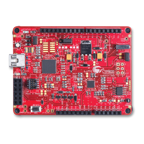
System Power Supply Jumper (J9) RGB LED (LED3) Proximity Header (J5) PSoC 4 Power Supply Jumper (J13) USB Connector (J10) PSoC 5LP (68QFN) Programmer and Debugger Power LED (LED1) PSoC 4000 (24 QFN) PSoC 5LP Cypress F‐RAM 256 Kb I/O Header (J8) PSoC 4 Reset Button Arduino Arduino PSoC 4 External Compatible I/O Compatible I/O Program and Debug Header (J2) Header (J1) Header (J6) ® CY8CKIT-040 PSoC 4000 Pioneer Kit Guide, Doc. # 001-91316 Rev. *F... - Page 20 Kit Operation ® CY8CKIT-040 PSoC 4000 Pioneer Kit Guide, Doc. # 001-91316 Rev. *F...
-
Page 21: Kit Usb Connection
Kit Operation Kit USB Connection The PSoC 4000 Pioneer Kit connects to the PC over a USB interface (see Figure 3-2). The kit enu- merates as a composite device and three separate devices appear under the Device Manager in the Windows operating system. See Table 3-1, and Figure... -
Page 22: Programming And Debugging Psoc 4000
Kit Operation Programming and Debugging PSoC 4000 The kit allows programming and debugging of the PSoC 4 device in two modes: 3.3.1 Using the Onboard PSoC 5LP Programmer and Debugger ■ 3.3.2 Using the CY8CKIT-002 MiniProg3 Programmer and Debugger ■ 3.3.1 Using the Onboard PSoC 5LP Programmer and Debugger The default programming interface for the kit is a USB-based, onboard programming interface. -
Page 23: Using The Cy8Ckit-002 Miniprog3 Programmer And Debugger
Kit Operation 3. The kit’s onboard programmer will enumerate on the PC and in the software tools as KitProg. Open an example project in PSoC Creator (such as Project: Blinking LED on page 54) and initiate the build by choosing Build > Build Project or pressing [Shift] [F6]. See Figure 3-6. - Page 24 Kit Operation Note The CY8CKIT-002 MiniProg3 is not part of the PSoC 4000 Pioneer Kit contents. It can be pur- chased from the Cypress Online Store. Figure 3-8. PSoC 4 Programming/Debug Using MiniProg3 Figure 3-9. MiniProg3 Configuration in PSoC Creator Note: Ensure that both MiniProg3 (with or without power) on header J6 and KitProg are not con- nected to the onboard PSoC 4 at the same time.
-
Page 25: Usb-I2C Bridge
Kit Operation USB-I C Bridge The PSoC 5LP also functions as a USB-I C bridge. The PSoC 4 communicates with the PSoC 5LP using an I C interface, and the PSoC 5LP transfers the data over the USB to the USB-I C software utility on the PC called the Bridge Control Panel (BCP). -
Page 26: Usb-Uart Bridge
Kit Operation To use the USB-I C functionality, select the KitProg USB-I C in the BCP (Figure 3-10). On success- ful connection, the Connected and Powered status boxes turn green (Figure 3-11). Figure 3-11. KitProg USB-I C Connected in Bridge Control Panel USB-I C is implemented using the USB and I C components of PSoC 5LP. -
Page 27: Updating The Onboard Programmer Firmware
167), PSoC Programmer displays a warning indicating that new firmware is available. Open PSoC Programmer from Start > All Programs > Cypress > PSoC Programmer<version>. When PSoC Programmer opens, a WARNING! window pops up saying that the programmer is cur-... - Page 28 Kit Operation Click OK to close the window. On closing the warning window, the Actions and Results window dis- plays Please navigate to the Utilities tab and click the Upgrade Firmware button, as shown in Figure 3-13. Figure 3-13. Upgrade Firmware Message in PSoC Programmer Click the Utilities tab and then the Upgrade Firmware button.
-
Page 29: Hardware
PSoC 5LP GPIO header (J8) ❐ Proximity header (J5) ❐ Pioneer board LEDs ❐ Push button (Reset button) ❐ Cypress ferroelectric RAM (F-RAM) ❐ CY8CKIT-040 CapSense Trackpad shield board (see Figure 4-2) ■ Note: Programming header J7 is not populated by default. ®... - Page 30 Hardware Figure 4-1. CY8CKIT-040 - Baseboard Details Coin Cell Battery Hoder (BT1) ® CY8CKIT-040 PSoC 4000 Pioneer Kit Guide, Doc. # 001-91316 Rev. *F...
- Page 31 Hardware Figure 4-2. CY8CKIT-040 CapSense Trackpad Shield Board Details Figure 4-3. PSoC 4000 Pioneer Kit Pin Mapping ® CY8CKIT-040 PSoC 4000 Pioneer Kit Guide, Doc. # 001-91316 Rev. *F...
-
Page 32: Block Diagram
Figure 4-4. Figure 4-4. Block Diagram PSoC 4 is a new generation of programmable system-on-chip devices from Cypress for embedded applications. The PSoC 4000 family is the smallest member of the PSoC 4 platform with CapSense, TCPWM, I C master or slave, and up to 20 GPIOs support. PSoC 4000 is a cost-optimized, entry- level PSoC4 device targeted as socket replacements for obsolete and/or proprietary 8-bit and 16-bit MCUs. -
Page 33: Kit Component Details
■ Deep Sleep mode with wake-up on interrupt and I2C address detect ❐ Capacitive Sensing ■ Cypress Capacitive Sigma-Delta (CSD) provides best-in-class signal-to-noise ratio (SNR) and ❐ water tolerance Cypress-supplied software component makes capacitive sensing design easy ❐ Automatic hardware tuning (SmartSense™) ❐... - Page 34 Hardware Industry-Standard Tool Compatibility ■ After schematic entry, development can be done with ARM-based industry-standard develop- ❐ ment tools 4.3.1.2 PSoC 5LP An onboard PSoC 5LP (CY8C5868LTI-LP039) is used to program and debug PSoC 4. The PSoC 5LP connects to the USB port of the PC through a USB Mini-B connector and to the SWD interface of the PSoC 4 device.
- Page 35 Hardware Digital peripherals ■ 20 to 24 programmable logic device (PLD)-based universal digital blocks (UDBs) ❐ Full CAN 2.0b 16 RX, 8 TX buffers ❐ Full-Speed (FS) USB 2.0 12 Mbps using internal oscillator ❐ Four 16-bit configurable timers, counters, and PWM blocks ❐...
- Page 36 Hardware Precision, programmable clocking ■ 3- to 62-MHz internal oscillator over full temperature and voltage range ❐ 4- to 25-MHz crystal oscillator for crystal PPM accuracy ❐ Internal PLL clock generation up to 67 MHz ❐ 32.768-kHz watch crystal oscillator ❐...
- Page 37 Hardware ® CY8CKIT-040 PSoC 4000 Pioneer Kit Guide, Doc. # 001-91316 Rev. *F...
- Page 38 Hardware Protection Circuit The power supply rail has reverse-voltage, overvoltage, short circuits, and excess current protection features, as seen in Figure 4-5. The Schottky diode (D4) ensures power cannot be supplied to the 5-V domain of the board from ■ the I/O header.
- Page 39 Hardware When using a separate power supply for the PSoC 4 with USB powering (regulator output on the ■ USB supply must be within 0.5 V of the separate power supply), remove jumper J13. Connect the positive terminal of voltage supply to the positive terminal of the ammeter and the negative termi- nal of the ammeter to the lower pin (P4.VDD) of J13.
- Page 40 Hardware 4.3.1.5 Arduino Compatible Headers (J1, J2, J3, J4, and J12) This kit has five Arduino compatible headers: J1, J2, J3, J4, and J12. You can develop applications based on the Arduino shield's hardware. An Arduino shield compatible Trackpad board is also sup- plied with the kit.
- Page 41 Hardware Figure 4-9. Arduino Compatible Headers Functionality of Unpopulated Header J12 The J12 header is a 2×3 header that supports Arduino shields. This header is used on a small sub- set of shields and is unpopulated on the PSoC 4000 Pioneer Kit. Note: The J12 header functions only in 5 V mode.
- Page 42 Hardware 4.3.1.6 PSoC 5LP GPIO Header (J8) A limited set of PSoC 5LP pins are brought to this header. Refer to Developing Applications for PSoC 5LP on page 130 for details on how to develop custom applications. See Pin Assignment Table on page 163 for pin details.
- Page 43 Hardware 4.3.1.7 CapSense Circuit The baseboard contains a header (J5) for CapSense proximity wire connection (see Figure 4-12). A 2.2-nF capacitor (C1) is present on CMOD pin, P0[4], for CapSense operation. An optional resistor R1 can be loaded to convert the current output from IDAC to a voltage output in non-CapSense applications.
- Page 44 Hardware 4.3.1.8 Board LEDs The PSoC 4000 Pioneer Kit board has three LEDs. A green LED (LED2) indicates the status of the programmer. See KitProg Status LED States on page 167 for a detailed list of LED indications. An amber LED (LED1) indicates the status of power supplied to the board. The kit also has a general- purpose tricolor (RGB) LED (LED3) for user applications that connect to specific PSoC 4 pins.
- Page 45 Hardware Figure 4-15. Status LED and RGB LED 4.3.1.9 Push Buttons The kit contains only a Reset push button, as shown in Figure 4-16. The Reset button is connected to the XRES pin of PSoC 4 and is used to reset the onboard PSoC 4 device. The push button con- nects to ground on activation (active low).
- Page 46 Hardware 4.3.1.10 Cypress Ferroelectric RAM (F-RAM) The baseboard contains an F-RAM device (FM24W256); see Figure 4-17, which can be accessed through I C lines by either of the PSoC devices – PSoC 5 LP or PSoC 4 – or by both. The F-RAM is 256 Kb (32 KB) in size with the I C speed up to 1 Mbps.
-
Page 47: Cy8Ckit-040 Capsense Trackpad Shield Board
Hardware 4.3.2 CY8CKIT-040 CapSense Trackpad Shield Board The kit also includes an Arduino-compatible CapSense Trackpad shield board. The Trackpad in the kit is a 6x5 elements capacitive sensing array. Figure 4-18 shows the pin mapping of the Trackpad. The modulation capacitor (Cmod) used for CapSense is connected to pin P0[4], and an optional bleeder resistor (R1) can be connected across the Cmod. - Page 48 Hardware Figure 4-18. CapSense Trackpad Shield Board ® CY8CKIT-040 PSoC 4000 Pioneer Kit Guide, Doc. # 001-91316 Rev. *F...
-
Page 49: Code Examples
54. Follow these steps to open and program an example project: 1. Launch PSoC Creator from the Windows Start menu (Start > All Programs > Cypress > PSoC Creator<version> > PSoC Creator<version>). 2. Open the example project by clicking <Project_name>.cywrk below Examples and Kits > Kits >... - Page 50 Code Examples 3. Build the code example by choosing Build > Build CY8CKIT_040_Blinking_LED.cywrk to gen- erate the hex file, as shown in Figure 5-2. Figure 5-2. Build Project from PSoC Creator 4. To program, connect the board to a computer using the USB cable connected to port J10, as described in Kit USB Connection on page 21.
- Page 51 Code Examples 6. If the device is not yet acquired, PSoC Creator will open the Select Debug Target window. Select KitProg/<ID> and click the Port Acquire button, as shown in Figure 5-4. Figure 5-4. Acquire Device from PSoC Creator 7. After the device is acquired, it is listed in a tree structure below the KitProg (see Figure 5-5).
- Page 52 Code Examples 8. Click OK to exit the window and start programming, as shown in Figure 5-6. Figure 5-6. Program Device from PSoC Creator Notes: The Debug port is disabled by default in one of the example projects (Project: CapSense Proxim- ■...
- Page 53 Code Examples Figure 5-7. R57 Location on the Board Figure 5-8. Debug Port Pin Functionality Selection ® CY8CKIT-040 PSoC 4000 Pioneer Kit Guide, Doc. # 001-91316 Rev. *F...
-
Page 54: Project: Blinking Led
Code Examples Project: Blinking LED 5.2.1 Project Overview The CY8CKIT_040_Blinking_LED.cyprj example uses a PWM block to blink the red LED of the RGB LED, as shown in Figure 5-9. The PWM output is connected to pin P3_2 (red) of the RGB LED. The PWM block is configured as a digital clock signal generator with a frequency of 1 Hz. -
Page 55: Project Description
Code Examples 5.2.2 Project Description 5.2.2.1 PSoC Creator Component Configuration PWM (TCPWM mode) The TCPWM Component is configured as a PWM with the parameters shown in Figure 5-10. Figure 5-10. TCPWM Component Parameters ® CY8CKIT-040 PSoC 4000 Pioneer Kit Guide, Doc. # 001-91316 Rev. *F... -
Page 56: Verify Output
Code Examples 5.2.2.2 Firmware Details Figure 5-11 shows the flow chart of code implemented in main.c. Figure 5-11. Blinking LED Project Flow Chart Start Initialize and Start PWM component Put CPU to sleep 5.2.2.3 Hardware Connections No specific hardware connections are required for this project because all connections are hard- wired on the board. -
Page 57: Project: Capsense Proximity And Uart
Code Examples Project: CapSense Proximity and UART 5.3.1 Project Overview The project CY8CKIT_040_Proximity_UART.cyprj implements a capacitive proximity sensor con- trolling the brightness of a LED. The project configures the sensor as a CapSense proximity widget with SmartSense Auto-tuning. Firmware Details on page 61 presents the firmware flow and explains the firmware blocks in detail. -
Page 58: Project Description
Code Examples 5.3.2 Project Description 5.3.2.1 PSoC Creator Component Configuration CapSense The CapSense Component is configured in SmartSense Auto-tuning mode with one proximity sen- sor for the design with the parameters shown in Table 5-2. Table 5-2. CapSense Component Parameters Parameter Tab Present Value... - Page 59 Code Examples Component to generate the proper period macro for the 15-bit PRSm. Though the output of PRSm has a variable frequency with a maximum frequency of 8 MHz (16 MHZ/2), the repeat rate of PRSm is considered to be the period in this context. Note: The Compare value should be a minimum of '1';...
- Page 60 Code Examples TX (Software TX UART) The software transmit TX is used to send out proximity sensor related data for debugging. The con- figuration for the component is shown in Figure 5-15. The TX pin is selected in firmware through the TX_PORT/TX_PIN macros defined in the main.h file.
- Page 61 Code Examples 5.3.2.2 Firmware Details Firmware Structure The firmware is written in a modular format, with different aspects of the functionality provided as separate functions for easy understanding. The header provides a list of handy macros for configur- ing the project's key aspects according to user requirements. The comments in the header file pro- vide the details on the macro.
- Page 62 Code Examples The firmware does the following: The CapSense/input initialization part tunes the CapSense system parameters using Smart- ■ Sense. The output initialization part configures the PWM and the software UART TX output. ■ The infinite loop code is divided into two phases: input process and output process. ■...
- Page 63 Code Examples Table 5-4 provides a quick reference to some key CapSense Component variables/arrays. Table 5-4. CapSense Component Key Variables Variable/Array Name Description Usage This array contains the raw data for each sensor. The array size is equal to the total number of sen- sors (CapSense_TOTAL_SENSOR_COUNT).
- Page 64 Code Examples Table 5-5 provides a quick reference to some key CapSense Component macro definitions. Table 5-5. CapSense Component Macros Macro Format Sample Description CapSense_TOTAL_SEN- Defines the total number of sensors – SOR_COUNT within the CapSense Component. The constant denotes the sensor number of a sensor in the CapSense block.
- Page 65 Code Examples Table 5-6. CapSense Component APIs Description/Usage The API sets the CapSense block settings for the selected widget and void CapSense_ScanWidget(uint32 starts scanning the widget. widget) It can be used if scanning of only an individual widget is desired. The API scans the selected sensor.
- Page 66 Code Examples 5.3.2.3 Hardware Connections A wire in the form of a loop is connected to jumper J5 (P2_0), as shown in Figure 5-17. To enable the UART TX connection to the PSoC 5LP USB-UART bridge, make sure R57 is populated on the board (by default it is populated on the board).
-
Page 67: Verify Output
0x00 0xFF 0xFF Follow these steps to set up the BCP for viewing the data: 1. Open the BCP software available from All Programs > Cypress > Bridge Control Panel <ver- sion> > Bridge Control Panel <version>. ® CY8CKIT-040 PSoC... - Page 68 Code Examples 2. Route the TX pin of the device to any available RX that can connect to the PC COM port. CY3240 (refer to AN2397) or KitProg in CY8CKIT-040 can be used for this purpose. Note: In CY8CKIT-040, Pin 3_0 is routed directly to the RX pin of the PSoC 5 LP USB-UART bridge through a zero-ohm resistor.
- Page 69 Code Examples 4. Select the COM port and RX8 as the protocol, as shown in Figure 5-21. Figure 5-21. Bridge Control Panel - COM Port and Protocol Selection 5. Choose Tools > Protocol Configuration or press [F7] and configure the RX8 protocol parame- ters, as shown in Figure 5-22.
- Page 70 Code Examples 6. Choose Chart > Variable Settings and set the variable names and types, as shown in Figure 5-23. Or click Load and then select the CapSense Proximity UART - Variable.ini file sup- plied with the project (...\Firmware\PSoC 4\Bridge Files\) in the Open window that appears.
- Page 71 Code Examples 8. Click the command line and then click Repeat, as shown in Figure 5-25 to start receiving the packets (make sure you have powered the device and programmed with the project's firmware, the TX is connected to the RX line of the COM, and the COM port is selected in the BCP). Figure 5-25.
- Page 72 Code Examples 9. You should start receiving data. Click the Chart tab to view the graph, as shown in Figure 5-26. Figure 5-26. Bridge Control Panel - Chart for Viewing Debug Data Signal LED Intensity (PRSm duty cycle) ® CY8CKIT-040 PSoC 4000 Pioneer Kit Guide, Doc.
- Page 73 Code Examples Raw count and Baseline ® CY8CKIT-040 PSoC 4000 Pioneer Kit Guide, Doc. # 001-91316 Rev. *F...
-
Page 74: Project: Capsense Touchpad With I2C Tuner
Code Examples Project: CapSense Touchpad with I C Tuner 5.4.1 Project Overview The project CY8CKIT_40_CapSense_I2C.cyprj demonstrates the implementation of a CapSense Trackpad using SmartSense and an EzI2C-based CapSense Tuner window for viewing the Track- pad coordinates. The project is a simple implementation using SmartSense (minimal tuning). The EzI2C block of PSoC 4000 is interfaced through the PSoC 5LP based USB-I C bridge to the PC GUI. - Page 75 Code Examples Figure 5-28. PSoC Creator Schematic Design of CapSense Trackpad Project with I C Tuner ® CY8CKIT-040 PSoC 4000 Pioneer Kit Guide, Doc. # 001-91316 Rev. *F...
-
Page 76: Project Description
Code Examples 5.4.2 Project Description 5.4.2.1 PSoC Creator Component Configuration CapSense The CapSense Component is configured in SmartSense Auto-tuning mode with a 6x5 CapSense touchpad widget for the design, according to the parameters given in Table 5-9. Table 5-9. CapSense Component Parameters Parameter Tab Present Value... - Page 77 Code Examples Figure 5-29. CapSense Touchpad Parameters SCB (EzI2C Mode) The Serial Communication Block (SCB) configured in EzI2C mode is used for the CapSense Tuner. The parameters of the Component are shown in Figure 5-30. Figure 5-30. SCB (EZI2C Mode) Component Parameters ®...
- Page 78 Code Examples 5.4.2.2 Firmware Details Figure 5-31 shows the flow chart of code implemented in main.c. Figure 5-31. CapSense Touchpad With I C Tuner Project Flow Chart Start Initialize CapSense and Enable Tuner Process CapSense and Send data over tuner 5.4.2.3 Hardware Connections Plug the Trackpad shield board into the Arduino headers of the kit, as shown in Figure 5-27.
-
Page 79: Verify Output
Code Examples Figure 5-32. Pin Selection for CapSense I C Project 5.4.3 Verify Output Build and program the code example and reset the device. Launch the CapSense Tuner window as explained in the following steps. 5.4.3.1 Launching Tuner Window The Tuner window from PSoC Creator must be up and running for the code example to work. To launch the GUI, follow these steps: 1. - Page 80 Code Examples 2. To launch the Tuner, right-click the CapSense Component in PSoC Creator and click Launch Tuner, as shown in Figure 5-34. Figure 5-34. Launch Tuner 3. The Tuner window opens. Click Configuration to open the configuration window, as shown in Figure 5-35.
- Page 81 Code Examples 5.4.3.2 Verify Output 1. To start the scanning and communication process, click Start in the Tuner window, as shown in Figure 5-37. Figure 5-37. Start Communication 2. Select a sensor in the Tuning tab. A red outline is displayed on the selected sensor. Different CapSense parameters are shown on the bottom right.
- Page 82 Code Examples 4. Select the sensor parameters to observe, as shown in Figure 5-39. The graph of the selected parameters appears. Figure 5-39. Sensor Parameter Graph ® CY8CKIT-040 PSoC 4000 Pioneer Kit Guide, Doc. # 001-91316 Rev. *F...
- Page 83 Code Examples 5. Touch a sensor or slider element and see the increase in Raw count and Signal, as shown in Figure 5-40. Figure 5-40. Raw Count Increase ® CY8CKIT-040 PSoC 4000 Pioneer Kit Guide, Doc. # 001-91316 Rev. *F...
-
Page 84: Project: Color Palette
Code Examples Project: Color Palette 5.5.1 Project Overview The project CY8CKIT_040_Color_Palette.cyprj demonstrates the capability of PSoC 4000 device to interface with a capacitive Trackpad and control an RGB LED based on the color selected by touch- ing the sticker on top of the Trackpad. The sticker will also include a slider area (part of Trackpad), which will control the color brightness of the RGB LED. - Page 85 Code Examples Table 5-11. CapSense Component Parameters Parameter Tab Present Value Rationale Automatically adjust sensitivity for different system Tuning method Auto(SmartSense) environments. Threshold mode General Automatic Enable run-time threshold calculation for 5:1 SNR. Raw data noise Filter out noise/unwanted spikes in raw count. This First Order IIR 1/8 filter setting can be tweaked based on requirement.
- Page 86 Code Examples Figure 5-42. CapSense Touchpad Parameters ® CY8CKIT-040 PSoC 4000 Pioneer Kit Guide, Doc. # 001-91316 Rev. *F...
- Page 87 Code Examples Figure 5-43. Scan Order Tab in CapSense Component Configure Window ® CY8CKIT-040 PSoC 4000 Pioneer Kit Guide, Doc. # 001-91316 Rev. *F...
- Page 88 Code Examples TX (SW TX UART) The software transmit TX is used to send out sensor data for debugging if enabled in firmware (refer to main.h in the project). The configuration for the Component is shown in Figure 5-44. The SW TX can be sent over to PC using either an RS-232 connector (with a voltage level translator in between) or through USB-UART bridge available in the CY8CKIT-040 PSoC 5 LP UART Bridge or CY3240 bridge configured as UART bridge, as documented in AN2397.
- Page 89 Code Examples 5.5.2.2 Firmware Details Firmware Structure The color palette firmware is written in a modular format with different aspects of the functionality provided in separate functions, source, and header files. This enables users to understand the firm- ware structure better and to modify the firmware easily to meet the application requirements. The key aspects of the firmware can be modified to meet a different application requirement using vari- ous macros defined in the main.h file.
- Page 90 Code Examples Firmware Flow Chart Figure 5-45 shows the flow chart of code implemented in main.c. Figure 5-45. Color Palette Project Flow Chart Start Enable proximity and initialize all blocks (CSD, PrISM, Debug Interface, and WDT) While(1) Loop Switch(MODE) SLEEP_SCAN PROX_SCAN ACTIVE ® CY8CKIT-040 PSoC 4000 Pioneer Kit Guide, Doc. # 001-91316 Rev. *F...
- Page 91 Code Examples Scan Proximity Scan all sensors Sensor including Prox Mode = SLEEP_SCAN Scan Gang Sensor Is it active? Is Prox Active? and Enter Sleep Scan Update PrISM duty based on End of loop Mode = PROX_SCAN Sleep Is it active? previous color and exit sleep scan and proximity distance Mode = ACTIVE Is Any Sensor and Exit sleep scan Active? End of loop Mode = ACTIVE End of loop ® CY8CKIT-040 PSoC 4000 Pioneer Kit Guide, Doc. # 001-91316 Rev. *F...
- Page 92 Code Examples Scan all sensors excluding Prox Is any sensor Increment NO_ACT active? counter Get Trackpad Is NO_ACT > 5 Is NO_ACT > 2.5 position secs? secs? Process co‐ ordinates to obtain color and brightness detail Mode = SLEEP_SCAN Start dimming LED and enter sleep scan Update PrISM duty based on color and brightness level Reset NO_ACT to 0 End of loop ® CY8CKIT-040 PSoC 4000 Pioneer Kit Guide, Doc. # 001-91316 Rev. *F...
- Page 93 Code Examples Firmware Implementation Details The firmware consists of three different modes: active scanning (ACTIVE_SCAN), sleep scanning (SLEEP_SCAN), and proximity scanning (PROX_SCAN) Active Scanning: Active scanning primarily performs two tasks: ■ Scans the touchpad ❐ Updates the color based on touchpad activity ❐...
- Page 94 Code Examples Figure 5-48 through Figure 5-51 explain the process of generating the intensity levels for the RGB LEDs. The color palette and the saturation slider are both part of the Trackpad area. The following steps summarize the flow. 1. The Trackpad coordinates are obtained as shown in the mapping in Figure 5-48.
- Page 95 Code Examples 2. Intensity levels of the RGB colors, before applying saturation, are calculated as shown in Figure 5-50. Along the X-Pos, the color palette is divided into six windows. In each window, one color is at maximum brightness, one is at minimum brightness, and one moves from maximum to minimum or vice versa.
- Page 96 Code Examples 3. After the primary color intensities (from the color palette) are derived from step 2, either the brightness level or the saturation level selected by the slider is applied. The selection between brightness and saturation is done using DO_SATURATION macro defined in main.h. a.
- Page 97 Code Examples Proximity Scanning Mode: ■ In proximity scanning mode, the device primarily scans the proximity sensor, and the touchpad sensors are scanned for activity. The previously selected RGB color is turned on with intensity proportional to the proximity signal strength. The device enters active scanning mode when a Trackpad element is touched.
- Page 98 Code Examples 5.5.2.3 Hardware Connections The example requires the CapSense Trackpad shield connection, as explained in Project: Cap- Sense Touchpad with I2C Tuner on page 74. The RGB LED and CMOD connections are hardwired on the board. Optionally, a proximity loop can be connected, as shown in setup 1 in Figure 5-52.
- Page 99 Code Examples Figure 5-53. Setup 2 Open CY8CKIT_040_Color_Palette.cydwr under the Source vertical tab in the Workspace Explorer and select the suitable pin. Table 5-13. Pin Connection Pin Name Port Name Trackpad_X0 P0_3 Trackpad_X1 P0_7 Trackpad_X2 P0_6 Trackpad_X3 P0_5 Trackpad_X4 P0_0 Trackpad_X5 P0_1 Trackpad_Y0...
- Page 100 Code Examples Figure 5-54. Pin Selection for Color Palette Project ® CY8CKIT-040 PSoC 4000 Pioneer Kit Guide, Doc. # 001-91316 Rev. *F...
-
Page 101: Verify Output
Code Examples 5.5.3 Verify Output Build and program the code example onto the device. The default color for the RGB LEDs is blue. Therefore, when you move over the proximity sensor before touching the Trackpad, the RGB LED turns blue. Follow these steps to verify the code. 1. -
Page 102: Adc In Psoc 4000
Follow these steps to open and use the PSoC Creator CSD_ADC code example. 1. Launch PSoC Creator from Start > All Programs > Cypress > PSoC Creator <version> > PSoC Creator <version>. Note that the CSD_ADC Component is supported in PSoC Creator 3.2 or higher. - Page 103 Code Examples 2. On the Start page, click Find Example Project… under Examples and Kits, as shown in Figure 5-57. Figure 5-57. Open Code Example from PSoC Creator 3. In the Find Example Project window, set the Device family to PSoC 4000 and Keyword to CSD_ADC as shown in Figure 5-58.
- Page 104 Code Examples 5. Select ADC_VoltageInput and click the Create New Workspace button. Save the workspace to a desired location. 6. This example demonstrates a voltage ADC implementation in PSoC 4000. The example also explains how to perform a two-point calibration for improved accuracy. The firmware controls a PWM output based on ADC output and the ADC data is sent out through UART as well.
-
Page 105: Advanced Topics
Advanced Topics This section describes some of the advanced features available in the kit. Note: For all new example projects created in this section, rename the Components as shown in associated Component images. This is required because the C files attached with the user guide fol- low the Component names as shown in these images. - Page 106 Advanced Topics 2. Drag and drop an I C Component to the top design, as shown in Figure 6-2. Figure 6-2. I C Component in Component Catalog 3. To configure the I C Component, double-click or right-click the I C Component and select Con- figure, as shown in Figure 6-3.
- Page 107 Advanced Topics 4. Configure the I C with the settings and click OK, as shown in Figure 6-4 Figure 6-5. Figure 6-4. I C ‘Configuration’ Tab Figure 6-5. ‘I C Tab ® CY8CKIT-040 PSoC 4000 Pioneer Kit Guide, Doc. # 001-91316 Rev. *F...
- Page 108 Advanced Topics 5. Select pin P1[2] for the I C SCL and pin P1[3] for the I C SDA in the Pins tab of <project.cydwr>, as shown in Figure 6-6. Figure 6-6. Pin Selection 6. Place the code available in USB_I2C-main.c, which is attached to this PDF document, in your main.c project file.
- Page 109 I C block will be generated. Figure 6-7. Clock Settings in cydwr File 8. Open BCP from Start > All Programs > Cypress > Bridge Control Panel <version number>. ® CY8CKIT-040 PSoC 4000 Pioneer Kit Guide, Doc. # 001-91316 Rev. *F...
- Page 110 Advanced Topics 9. Connect to KitProg/ under Connected I C/SPI/RX8 Ports, as shown in Figure 6-8. Figure 6-8. Connect to KitProg/ in BCP ® CY8CKIT-040 PSoC 4000 Pioneer Kit Guide, Doc. # 001-91316 Rev. *F...
- Page 111 Advanced Topics 10.Open Protocol Configuration from the Tools menu and select the appropriate I C Speed. Make sure the I C speed is the same as the one configured in the I C Component. Click OK to close the window, as shown in Figure 6-9.
- Page 112 Advanced Topics Figure 6-11. NACK Indication in BCP ‘‐’ Indicates No Acknowledgment (NACK) 12.From the BCP, read five bytes of data from the I C slave device with slave address 0x08, as shown in Figure 6-12. The log shows whether the transaction was successful. Figure 6-12.
-
Page 113: Using Fm24W256 F-Ram
The PSoC 4000 Pioneer Kit has an onboard Ferroelectric RAM chip that can hold up to 32 KB of data. Cypress F-RAM products combine the nonvolatile data storage capability of ROM with the benefits of RAM, which include a high number of read and write cycles, high-speed read and write cycles, and low power consumption. -
Page 114: Write/Read Operation
Advanced Topics 6.2.2 Write/Read Operation The device datasheet includes details on how to perform a write/read operation with the F-RAM. Figure 6-14 Figure 6-15 provide a snapshot of the write/read packet structure as a quick refer- ence. Figure 6-14. F-RAM Single/Multiple-Byte Write Packet Structure Figure 6-15. -
Page 115: Example Firmware
Advanced Topics In the previous figures, "Slave Address" denotes the address of the F-RAM slave device. [Address MSB: Address LSB] forms the 16-bit address of the memory location in the F-RAM to be accessed for read/write operation. The first two bytes following the slave address byte during a write operation constitute the initial memory address to be accessed. - Page 116 Advanced Topics 2. From the Components Catalog, place an I C (SCB mode) Component in the TopDesign from Communication > I C > I C (SCB mode) [<version>] and configure it as I C in the Configura- tion tab with the parameters shown in Figure 6-17.
- Page 117 Advanced Topics 7. In the command window, copy and paste the code from the F-RAM_BCP_Commands.txt file attached to this document. 8. By default the F-RAM device is configured with a 0x50 slave address. If the value has been changed as explained in Address Selection on page 113, then change the slave address in the command window (replace “50”...
-
Page 118: Using Psoc 5Lp As A Usb-Uart Bridge
Advanced Topics 10.If the write transfer is successful, then check back the data using a read command to the same address by sending the second command line, as shown in Figure 6-20. The read command on the same locations will yield a '0' at 0x0000 (flag cleared) and 0xFD at 0x0001 (inverse of 0x02 sent). - Page 119 Advanced Topics 1. Create a new PSoC 4 project in PSoC Creator, as shown in Figure 6-21. Select an appropriate location for your project and rename it as required. Figure 6-21. Create a New Project From PSoC Creator ® CY8CKIT-040 PSoC 4000 Pioneer Kit Guide, Doc.
- Page 120 Advanced Topics 2. Drag and drop a UART (SCB) component from the Component Catalog shown in Figure 6-22 the top design. Figure 6-22. UART Component Under Component Catalog 3. To configure the UART, double-click or right-click the UART Component and select Configure, as shown in Figure 6-23.
- Page 121 Advanced Topics 4. Configure the UART as shown in Figure 6-24, Figure 6-25, and Figure 6-26 and then click OK. Figure 6-24. ‘Configuration’ Tab Figure 6-25. ‘UART Basic’ Tab ® CY8CKIT-040 PSoC 4000 Pioneer Kit Guide, Doc. # 001-91316 Rev. *F...
- Page 122 Advanced Topics Figure 6-26. ‘UART Advanced’ Tab 5. Select P4[0] for UART RX and P4[1] for UART TX in the Pins tab of <Project_Name>.cydwr, as shown in Figure 6-27. Figure 6-27. Pin Selection 6. Place the code available in USB_UART-main.c, which is attached to this PDF document, in your main.c project file.
- Page 123 Advanced Topics 8. Connect the RX line of the PSoC 4 to J8_10 and the TX line of the PSoC 4 to J8_9, as shown in Figure 6-28 Figure 6-29. Notes: Before connecting the RX line, remove R57 connecting P3[0] of the PSoC 4000 device to the ■...
- Page 124 Advanced Topics Note: UART RX and UART TX can be routed to any digital pin on PSoC 4 based on the configura- tion of the UART Component. An SCB implementation of the UART will route the RX and TX pins to either one of the following subsets: (P0[4], P0[5]) or (P3[0],P3[1]) or (P4[0],P4[1]).
- Page 125 Advanced Topics 2. Open HyperTerminal, choose File > New Connection, enter a name for the new connection, and click OK, as shown in Figure 6-31. Figure 6-31. Open New Connection HyperTerminal 3. For PuTTY, double-click the PuTTY icon and select Serial under Connection, as shown in Figure 6-32.
- Page 126 Advanced Topics 4. A new window opens, where you can select the communication port, as shown in Figure 6-33. a. In HyperTerminal, select COMx (or the specific communication port that is assigned to the Kit- Prog USB-UART) in Connect using and click OK. This code example uses COM12. b.
- Page 127 Advanced Topics 5. In HyperTerminal, select Bits per second, Data bits, Parity, Stop bits, and Flow control under Port Settings and click OK, as shown in Figure 6-34. Make sure that the settings are identical to the UART settings configured for PSoC 4. In PuTTY, select Speed (baud), Data bits, Stop bits, Parity, and Flow control under Configure the serial line shown in Figure 6-33...
- Page 128 Advanced Topics Figure 6-35. Select Communication Type in PuTTY 6. Enable Echo typed characters locally under File > Properties > Settings > ASCII Setup to display the typed characters in HyperTerminal, as shown in Figure 6-36. In PuTTY, enable Force on under Terminal >...
- Page 129 Advanced Topics Figure 6-37. Enable Echo of Typed Characters in PuTTY 7. The COM terminal software displays both the typed data and the echoed data from the PSoC 4 UART, as shown in Figure 6-38 Figure 6-39. Figure 6-38. Data Displayed on HyperTerminal ®...
-
Page 130: Developing Applications For Psoc 5Lp
Advanced Topics Figure 6-39. Data Displayed on PuTTY Developing Applications for PSoC 5LP The PSoC 4000 Pioneer Kit has an onboard PSoC 5LP whose primary function is that of a program- mer and a bridge. You can build either a normal project or a bootloadable project using the PSoC 5LP. -
Page 131: Building A Bootloadable Project For Psoc 5Lp
Advanced Topics Figure 6-40. PSoC 5LP Block Diagram 6.4.1 Building a Bootloadable Project for PSoC 5LP All bootloadable applications developed for the PSoC 5LP should be based on the bootloader hex file, which is programmed onto the kit. The bootloader hex file is available in the kit files or can be downloaded from the kit webpage. - Page 132 Advanced Topics To build a bootloadable application for the PSoC 5LP, follow this procedure: 1. In PSoC Creator, choose New > Project > PSoC 5LP; click the expand button adjacent to Advanced and select the Device as CY8C5868LTI-LP039, as shown in Figure 6-42.
- Page 133 Advanced Topics 2. Navigate to the schematic view and drag and drop a Bootloadable Component on the TopDesign. Figure 6-43. Bootloadable Component in Component Catalog ® CY8CKIT-040 PSoC 4000 Pioneer Kit Guide, Doc. # 001-91316 Rev. *F...
- Page 134 Advanced Topics 3. Set the dependency of the Bootloadable Component by selecting the Dependencies tab in the configuration window and clicking the Browse button, as shown in Figure 6-44. Select the Kit- Prog_Bootloader.hex and KitProg_Bootloader.elf files; click Open, as shown in Figure 6-45 Figure 6-46 and then click OK on the Configuration window.
- Page 135 Advanced Topics Figure 6-45. Select KitProg Bootloader Hex File Figure 6-46. Select KitProg Bootloader Elf File ® CY8CKIT-040 PSoC 4000 Pioneer Kit Guide, Doc. # 001-91316 Rev. *F...
- Page 136 Advanced Topics 4. In the General tab, check the Manual application image placement checkbox and set the Placement address as “0x00002800” as shown in Figure 6-47. Figure 6-47. Bootloadable Component-General Tab 5. Develop your custom project. 6. The NVL setting of the Bootloadable project and the KitProg_Bootloader project must be the same.
- Page 137 Advanced Topics 9. To download the project onto the PSoC 5LP device, open the Bootloader Host tool, which is available from PSoC Creator. Choose Tools > Bootloader Host, as shown in Figure 6-49. Figure 6-49. Open Bootloader Host Tool from PSoC Creator 10.In the Bootloader Host tool, click Filters and add a filter to identify the USB device.
- Page 138 Advanced Topics 11. In the Bootloader Host tool, click the Open File button to browse to the location of the bootload- able file (*.cyacd), as shown in Figure 6-51. Figure 6-51. Open Bootloadable File from Bootloader Host Tool Figure 6-52. Select Bootloadable .cyacd File from Bootloader Host 12.Click the Program button in the Bootloader Host tool to program the device.
-
Page 139: Building A Normal Project For Psoc 5Lp
Pioneer Kit\<version>\Firm- ware\Programmer\KitProg This advanced functionality requires a MiniProg3 programmer, which is not included with this kit. The MiniProg3 can be purchased from www.cypress.com/go/CY8CKIT-002. To build a normal project for the PSoC 5LP, follow these steps: ® CY8CKIT-040 PSoC 4000 Pioneer Kit Guide, Doc. # 001-91316 Rev. *F... - Page 140 Advanced Topics 1. In PSoC Creator, choose New > Project > PSoC 5LP Design; click the expand button adjacent to Advanced and select Device as CY8C5868LTI-LP039; as shown in Figure 6-53. Figure 6-53. Create a New Project in PSoC Creator 2.
-
Page 141: Psoc 5Lp Factory Program Restore Instructions
■ PSoC 5LP Factory Program Restore Instructions The CY8CKIT-040 PSoC 4000 Pioneer Kit features a PSoC 5LP device that comes factory-pro- grammed as the onboard programmer and debugger for the PSoC 4 device. In addition to creating applications for the PSoC 4 device, you can also create custom applications... - Page 142 Advanced Topics 3. The following message shown in Figure 6-54 appears in the PSoC Programmer results window: "KitProg Bootloader device is detected." Figure 6-54. PSoC Programmer Results Window ® CY8CKIT-040 PSoC 4000 Pioneer Kit Guide, Doc. # 001-91316 Rev. *F...
- Page 143 Advanced Topics 4. Switch to the Utilities tab in PSoC Programmer and click the Upgrade Firmware button, as shown in Figure 6-55. Unplug all other PSoC programmers (such as MiniProg3 and DVKProg) from the PC before clicking the Upgrade Firmware button. Figure 6-55.
- Page 144 Advanced Topics 5. After programming is completed, the following message appears: “Firmware Update Finished at <time>,” as shown in Figure 6-56. Figure 6-56. Firmware Update Complete 6. The factory program is now successfully restored on the PSoC 5LP. It can be used as the pro- grammer/debugger for the PSoC 4 device.
- Page 145 Restore PSoC 5LP Factory Program Using USB Host Tool 1. Launch the Bootloader Host tool from Start > Cypress > PSoC Creator. Using the File > Open menu, load the Kit Prog.cyacd file, which is installed with the kit software.
- Page 146 Advanced Topics 2. Configure the Pioneer Kit in Service mode. To do so, while holding down the reset button (SW1 Reset), plug the PSoC 4000 Pioneer Kit into the computer using the included USB cable (USB A to Mini-B). This puts the PSoC 5LP into service mode, which is indicated by the blinking green status LED.
-
Page 147: Psoc 5Lp Programmed With A Standard Application
If PSoC 5LP is programmed with a standard application, restore the factory program by using the fol- lowing method. 1. Launch PSoC Programmer 3.23.1 or later from Start > Cypress > PSoC Programmer. 2. Use the File > Open menu to load the KitProg.hex factory program hex file, which is shipped with the kit. - Page 148 Advanced Topics 4. Ensure that MiniProg3 is the selected port in PSoC Programmer and the 10-pin connector (10p option) is selected, as shown in Figure 6-60. If the board is not powered over USB, select the Power Cycle programming mode. Figure 6-60.
-
Page 149: Using Μc/Probe Tool
For more details on licensing and the µC/Probe tool, refer to the µC/Probe Users’ Manual at http://micrium.com/download/%c2%b5cprobe-3-0-users-manual/. In Micrium µC/Probe version 3.3, the Cypress KitProg is supported as a means of communication to the target device connected to the computer. When an example project is built in PSoC Creator, it produces the output files in HEX, LST, MAP, RPT, and ELF formats. - Page 150 Advanced Topics The ELF file lists all the symbols (variables), symbol types, and its addresses. The Micrium µC/ Probe tool reads the ELF file and detects these symbols (global variables) used in the code. The µC/Probe tool provides a host of graphical controls such as sliders, RGB palette, graphs, and donuts.
- Page 151 Advanced Topics 5. Drag and drop a RGB Palette from Writable Controls in the Toolbox onto the Datascreen to visualize the RGB output. Figure 6-63. Adding RGB Palette Control 6. Next, add a Line Chart from Charts in the Toolbox onto the Datascreen to visualize the X, Y posi- tion of the finger on the trackpad.
- Page 152 Advanced Topics 8. Click the ELF button in the Symbol Browser window. Figure 6-66. ELF Button in Symbol Browser 9. Browse and point to the CY8CKIT_040_Color_Palette.ELF file to load the symbols (global vari- ables) from the CapSense example project. Wait until the ELF file is loaded. The ELF file is in the collapsed state by default.
- Page 153 Advanced Topics 12.Drag and drop the global variable µcARGB on to the RGB Palette to see the RGB output. Simi- larly, drag and drop xPos and yPos on to the Line Chart control to the see the X and Y position of the finger on the trackpad.
- Page 154 Advanced Topics Figure 6-70. Assigning y Position Output to Line Chart Control 13.By default, the Y axis of the Line Chart is plotted for values between 0 and 10000. To change the Y axis scale to 0 to100, click the Line Chart control. In the Line Chart control toolbar that appears, click the Properties Editor icon.
- Page 155 Advanced Topics Figure 6-72. Properties Editor of Line Chart Control 14.In the Properties Editor, change the Max property of Y axis to 100. Notes: You may use the Series properties to change the line graph colors of xPos and yPos. Also, the Symbols Manager shows the global variables associated with the control.
- Page 156 Advanced Topics 16.In the µC/Probe setting window, select Cypress PSoC Prog and select KitProg/<Kit Prog num- ber> from the drop-down list for Port and click OK to start communication between the CY8CKIT- 040 and the µC/Probe tool. Figure 6-74. µC/Probe Settings 17.Click the Run button to start.
- Page 157 The µC/Probe project for the CY8CKIT_040_Proximity_UART project is already created and packaged along with the kit contents. The µC/Probe projects can be found in the installation folder at <Install directory>/ CY8CKIT-040 PSoC 4000 Pioneer Kit/<version>/uCProbe. 1. Open the CY8CKIT-040_Proximity_UART example project in PSoC Creator.
-
Page 158: Appendix
Appendix CY8CKIT-040 Schematics Input Voltage Range VIN is 5-12V NO LOAD TP1 RED V3.3 VBUS NO LOAD R2 ZERO NCP1117DTARKG SOD123 VOUT 3216 3216 10 uFd 25v 120 ohm 22 uFd 0603 232 ohm 1.0 uF CR2032 Coin Cell Battery Holder VBUS V3.3... - Page 159 Appendix PLACE CAPS CLOSE TO POWER PINS P4_VDD 0.1 uF 1.0 uF 0402 0603 ZERO ZERO P0_0 P1_6 P0[0] P1[6] ZERO ZERO P0_1 P1_5 P0[1] P1[5] ZERO P0_2 P1_4 P0[2] P1[4] CY8C4014LQI-422 ZERO P0_3 P1_3 P0[3] P1[3] P0_4 P1_2 P0[4] P1[2] P1_1 VCCD...
- Page 160 Appendix /XRES P3_1 P1_7 P1_1 EVQ-PE105K /XRES P2_0 RESET 3x2 RECPT 1x1 RECP NO LOAD Proximity Header 2 PIN HDR J12 Arduino ICSP compatible header LED_PWR P4_VDD P4_VDD LED3 2.2K 1.5K P3_2 P1_1 I2C Pull up Resistors 2.2K 2.2K LED_PWR 1.5K P0_2 P1_2...
- Page 161 Appendix VTARG P5LP_VDD R32 ZERO P3_0 P5LP1_2 P5LP0_0 P5LP0_1 P5LP12_2 R33 ZERO P5LP3_4 P5LP3_5 P5LP12_3 P3_1 R57 ZERO P5LP3_6 P5LP3_7 P3_0 P5LP12_6 P5LP12_7 0402 0.1 uF R34 ZERO P5LP3_0 P5LP12_4 /XRES 6x2 RECPT 50MIL KEYED SMD PSoC 5LP GPIO Extension Header PSoC 4 / External PSoC Program/Debug Header P5LP_VDD 1.0 uF...
- Page 162 Appendix P1_2 0.1 uF 0402 P1_3 FM24W256 ZERO ZERO ZERO ZERO NO LOAD NO LOAD NO LOAD NO LOAD ZERO ZERO ZERO ZERO F-RAM A.1.1 CapSense Touchpad Shield Board P1_2 P1_3 CSX1 P1_7 P3_1 P1_4 P1_1 ROW0 V5.0 P1_6 V3.3 P1_5 /XRES P1_4...
-
Page 163: Pin Assignment Table
Appendix Pin Assignment Table This section provides the pin map of the headers and their usage. A.2.1 Arduino Compatible Headers (J1, J2, J3, J4, and J12) Power Connector (J1) Baseboard Signal Trackpad Shield Signal J1_01 J1_02 J1_03 J1_04 V5.0 J1_05 V3.3 J1_06 RESET... - Page 164 Appendix J4 Connector Baseboard Signal Trackpad Shield Signal J4_01 (D0) P0[5] TRACK_COLUMN2 J4_02 (D1) P0[6] TRACK_COLUMN3 J4_03 (D2) P0[7] TRACK_COLUMN4 J4_04 (D3) P3[2] (TCPWM_LINE, Red LED) J4_05 (D4) P0[3] TRACK_COLUMN5 J4_06 (D5) P3[0] (SWDIO) J4_07 (D6) P1[0] TRACK_ROW3 J4_08 (D7) P2[0] (PROX) Kit Signal PSoC 4 Description...
-
Page 165: Program And Debug Headers
Appendix A.2.2 PSoC 5LP GPIO Header (J8) J8 is a 2×6 header that connects PSoC 5LP pins to support GPIO controls for custom PSoC 5LP projects. PSoC 5LP PSoC 5LP PSoC 5LP Description PSoC 5LP Description Signal Signal J8_01 PSoC 5LP_VDD VDD J8_02 P1[2] Digital I/O... -
Page 166: Use Of Zero-Ohm Resistors And No Load
Appendix Use of Zero-ohm Resistors and No Load Unit Resistor Usage Power supply Solder zero-ohm resistors to access voltage from VBUS (USB). Unsolder the resistors to communicate with an external PSoC C connection between PSoC 5LP R24 and R25 using the PSoC 5LP. Removing these will disable the PSoC 4 I and PSoC 4 communication with the PSoC 5LP device. -
Page 167: Kitprog Status Led States
Appendix KitProg Status LED States User Indication Scenario Action Required by user Bootload the KitProg.cyacd file: in PSoC Programmer, con- LED blinks fast: LED starts blinking at power up, nect to the kit, open the Utilities tab and press Upgrade if bootloadable file is corrupt. -
Page 168: Bill Of Materials
CY8CKIT-040 Baseboard Reference Value Description Manufacturer Mfr Part Number PCB, 68.58 mm x 53.34 mm, High Tg, ENIG finish, 4 layer, Color = RED, Silk Cypress = WHITE. 2200 pFd CAP CER 2200PF 50V 5% NP0 0805 Murata GRM2165C1H222JA01D C2,C9,C10,C12, C14,C15,C17,C2 0.1 uFd... - Page 169 5V 350W TVS UNIDIR 350W 5V SOD-323 Dioded Inc. SD05-7 NCP1117DTAR NCP1117DTARKG ON Semiconductor NCP1117DTARKG PSoC 4 S0 Cypress Semiconduc- 24 QFN PSoC4 S0 target chip CY8C4014LQI-422 (CY8C400) PSoC 5LP 68QFN PSoC 5LP chip for USB debug Cypress Semiconduc- (CY8C5868LTI- CY8C5868LTI-LP039...
- Page 170 Reference Value Description Manufacturer Mfr Part Number PCB, 53.34 mm x 53.34 mm, High Tg, ENIG finish, 2 layer, Color = RED, Silk Cypress = WHITE. CONN HEADER 8POS .100 STR J1,J4 CON8 68001-108HLF 30AU CONN HEADER 6POS .100 STR...
-
Page 171: Trackpad/Touchpad Sticker Details
Appendix Trackpad/Touchpad Sticker Details Regulatory Compliance Information The CY8CKIT-040 PSoC 4000 Pioneer Kit has been tested and verified to comply with the following electromagnetic compatibility (EMC) regulations: EN 55022:2010 Class A - Emissions ■ EN 55024:2010 Class A - Immunity ■... -
Page 172: Migrating Projects Across Different Pioneer Series Kits
Appendix Migrating Projects Across Different Pioneer Series Kits All Cypress Pioneer series kits are Arduino Uno compatible and have some common onboard peripherals such as RGB LED, CapSense, and user switch. However, the pin mapping in each of the boards is different due to differences in pin functions of the PSoC device used. This guide lists the pin maps of the Pioneer series kits to allow for easy migration of projects across different kits. - Page 173 Appendix A.9.1 Arduino Uno Compatible Headers J1 Arduino Compatible Header Pin Map Pioneer Series Kits Pin # Arduino Pin CY8CKIT-042 CY8CKIT-040 CY8CKIT-042-BLE CY8CKIT-044 V5.0 V5.0 V5.0 V5.0 3.3V V3.3 V3.3 V3.3 V3.3 RESET RESET RESET RESET RESET IOREF P4.VDD P4.VDD BLE.VDD P4.VDD J2 Arduino Compatible Header Pin Map...
- Page 174 Appendix J3 Arduino Compatible Header Pin Map Pioneer Series Kits Pin # Arduino Pin CY8CKIT-042 CY8CKIT-040 CY8CKIT-042-BLE CY8CKIT-044 P2[6] P1[4] P0[5] P0[2] P3[6] P1[5] P0[4] P0[3] P3[4] P1[6] P0[2] P2[7] P3[0] P0[0] P6[0] P1[1] P3[1] P3[1] P0[1] P6[1] P0[6] P1[7] P0[3] P6[2] AREF...
- Page 175 Appendix A.9.2 Onboard Peripherals CapSense Pin Map Pioneer Series Kits Pin # Description CY8CKIT-042 CY8CKIT-042-BLE CY8CKIT-044 CY8CKIT-040 (Linear Slider) (Linear Slider) (Gesture Pad) CSS1 P1[1] – P2[1] P4[4] CSS2 P1[2] – P2[2] P4[5] CSS3 P1[3] – P2[3] P4[6] CSS4 P1[4] –...
-
Page 176: Revision History
Revision History Document Revision History Document Title: CY8CKIT-040 PSoC® 4000 Pioneer Kit Guide Document Number: 001-91316 Origin of Revision ECN# Issue Date Description of Change Change 4363580 04/21/2014 RKAD New kit guide. Updated Introduction chapter on page Updated “Additional Learning Resources” on page Updated “Learning PSoC Creator”... - Page 177 Index Document Revision History (continued) Document Title: CY8CKIT-040 PSoC® 4000 Pioneer Kit Guide Document Number: 001-91316 Origin of Revision ECN# Issue Date Description of Change Change Updated Code Examples chapter on page Updated “Project: Blinking LED” on page Updated “Project Description” on page Updated “PSoC Creator Component Configuration”...
- Page 178 Index Document Revision History (continued) Document Title: CY8CKIT-040 PSoC® 4000 Pioneer Kit Guide Document Number: 001-91316 Origin of Revision ECN# Issue Date Description of Change Change Updated Advanced Topics chapter on page 105: Updated description. Updated “Using PSoC 5LP as a USB-I2C Bridge” on page 105: Updated Figure...
- Page 179 Index Document Revision History (continued) Document Title: CY8CKIT-040 PSoC® 4000 Pioneer Kit Guide Document Number: 001-91316 Origin of Revision ECN# Issue Date Description of Change Change Updated Appendix chapter on page 158: Updated “KitProg Status LED States” on page 167: *A (cont.) 4681349 03/09/2015...
- Page 180 Index Document Revision History (continued) Document Title: CY8CKIT-040 PSoC® 4000 Pioneer Kit Guide Document Number: 001-91316 Origin of Revision ECN# Issue Date Description of Change Change Updated Code Examples chapter on page Renamed “Example Projects” with “Code Examples” in chapter heading. *C (cont.) 4802100 06/18/2015...
- Page 181 Index Document Revision History (continued) Document Title: CY8CKIT-040 PSoC® 4000 Pioneer Kit Guide Document Number: 001-91316 Origin of Revision ECN# Issue Date Description of Change Change Updated Advanced Topics chapter on page 105: Updated “Using PSoC 5LP as a USB-I2C Bridge” on page 105: Updated Figure...
Need help?
Do you have a question about the CY8CKIT-040 PSoC 4000 Pioneer Kit and is the answer not in the manual?
Questions and answers