
Related Manuals for Cypress PSoC 4 M Series


Summary of Contents for Cypress PSoC 4 M Series
- Page 1 CY8CKIT-043 ® PSoC 4 M-Series Prototyping Kit Guide Doc. #: 001-97606 Rev. ** Cypress Semiconductor 198 Champion Court San Jose, CA 95134-1709 Phone (USA): +1.800.858.1810 Phone (Intnl): +1.408.943.2600 www.cypress.com...
- Page 2 Cypress Source Code and derivative works for the sole purpose of creating custom software and or firmware in support of licensee product to be used only in conjunction with a Cypress integrated circuit as specified in the applicable agreement.
-
Page 3: Table Of Contents
Contents Safety Information 1. Introduction Kit Contents .........................7 PSoC Creator ......................8 1.2.1 PSoC Creator Code Examples ................9 1.2.2 Kit Code Example ..................10 1.2.3 PSoC Creator Help ..................10 Getting Started......................11 Additional Learning Resources..................11 Technical Support......................12 Document Conventions .....................12 2. Software Installation Before You Begin.......................13 Install Software ......................13 Uninstall Software......................15... - Page 4 Contents 5. Code Examples Using the Kit Code Example ..................33 Using Built-in PSoC Creator Code Examples with the Kit .........37 Appendix PSoC 4 M-Series Prototyping Kit Schematics ..............42 Programming the PSoC 4 M-Series Prototyping Kit Using MiniProg3/KitProg ....44 Bill of Materials ........................45 Revision History CY8CKIT-043 PSoC®...
-
Page 5: Safety Information
Safety Information Regulatory Compliance ® The CY8CKIT-043 PSoC 4 M-Series Prototyping Kit is intended for use as a development platform for hardware or software in a laboratory environment. The board is an open system design, which does not include a shielded enclosure. This may cause interference to other electrical or electronic devices in close proximity. - Page 6 General Safety Instructions ESD Protection ESD can damage boards and associated components. Cypress recommends that you perform procedures only at an ESD workstation. If such a workstation is not available, use appropriate ESD protection by wearing an antistatic wrist strap attached to the chassis ground (any unpainted metal surface) on your board when handling parts.
-
Page 7: Introduction
■ 3.3-V to 5.5-V operation ■ The PSoC 4 M-Series Prototyping Kit also integrates the Cypress KitProg, which enables onboard programming, debugging, and bridging functionality, such as USB-UART and USB-I C. The KitProg is used to program and debug the target PSoC 4200M device (see Figure 1-1). -
Page 8: Psoc Creator
Figure 1-2. PSoC Creator Features PSoC Creator also enables you to tap into an entire tool ecosystem with integrated compiler chains and production programming programmers for PSoC devices. For more information, visit www.cypress.com/psoccreator. Visit PSoC Creator training page for video tutorials on learning and using PSoC Creator. -
Page 9: Psoc Creator Code Examples
Introduction 1.2.1 PSoC Creator Code Examples PSoC Creator includes a large number of code examples. These examples are available from the PSoC Creator Start Page, as Figure 1-3 shows. Code examples can speed up your design process by starting you off with a complete design, instead of a blank page. -
Page 10: Kit Code Example
Introduction Figure 1-4. Code Example Projects with Sample Code 1.2.2 Kit Code Example In addition to the examples built into PSoC Creator, this kit includes a simple example, which can be used to quickly evaluate the functionality of this kit. The example is described in the Code Examples chapter on page 33. -
Page 11: Getting Started
■ MiniProg3, and the bill of materials (BOM). Additional Learning Resources Cypress provides a wealth of information at www.cypress.com to help you to select the right PSoC device for your design, and to help you to quickly and effectively integrate the device into your design. -
Page 12: Technical Support
PSoC developers ■ discussing the next generation embedded systems on Cypress Developer Community Forums. Technical Support If you have any questions, our technical support team is happy to assist you. You can create a support request on the Cypress Technical Support page. -
Page 13: Software Installation
Before You Begin All Cypress software installations require administrator privileges, but these are not required to run the software after it is installed. Close any other Cypress software that is currently running before installing the kit software. Note: By default, the kit contents are installed in C:\Program Files\Cypress for a 32-bit machine and C:\Program Files(x86)\Cypress for a 64-bit machine. - Page 14 Following are the required software: a. PSoC Creator 3.2 or later: This software is also available at www.cypress.com/psoccreator. b. PSoC Programmer 3.23 or later: This is installed as part of PSoC Creator installation (www.cypress.com/programmer).
-
Page 15: Uninstall Software
Uninstall Software The software can be uninstalled using one of the following methods: 1. Go to Start > All Programs > Cypress > Cypress Update Manager and select the Uninstall button next to the product that needs to be uninstalled. -
Page 16: Kit Operation
Kit Operation This chapter introduces you to the features of the PSoC 4 M-Series Prototyping Kit. It describes the programming and debugging functionality, KitProg USB-UART and USB-I C bridges, and the method to update the KitProg firmware. Theory of Operation Figure 3-1 shows the block diagram for the PSoC 4 M-Series Prototyping Kit. -
Page 17: Kitprog
The KitProg is a multi-functional system, which includes a programmer, debugger, USB-I C bridge, and a USB-UART bridge. The Cypress PSoC 5LP device is used to implement the KitProg functionality. The KitProg is integrated in most PSoC development kits. For more details on the... - Page 18 Kit Operation Figure 3-2. Connecting the PSoC 4 M-Series Prototyping Kit to a Computer 2. Open the desired project in PSoC Creator from File > Open > Project/Workspace. This provides the option to browse and open a previously saved project. If you want to open the example project provided with the kit, follow the instructions in the Code Examples chapter on page...
-
Page 19: Debugging Using Psoc Creator
Kit Operation Figure 3-4. Programming Device From PSoC Creator 3.3.2 Debugging Using PSoC Creator For debugging the project using PSoC Creator, follow steps 1 to 3 from Programming Using PSoC Creator on page 17 followed by these steps: 1. Click the Debug icon or press [F5]. -
Page 20: Hardware
Hardware Board Details The PSoC 4 M-Series Prototyping Kit consists of the following blocks: PSoC 4200M device U2 (CY8C4247AZI-M485) ■ PSoC 4200M headers J1 and J2 ■ PSoC 4200M 10-pin program/debug header J5 (footprint only) ■ KitProg (PSoC 5LP) device U1 (CY8C5868LTI-LP039) ■... - Page 21 Hardware Figure 4-1. PSoC 4 M-Series Prototyping Kit Pin Details KitProg P0_1 P12_7/UART TX P0_0 P12_6/UART RX P3_6 P12_1/I C SDA P3_5 P12_0/I C SCL P3_4 P12_5 P3_0 VBUS VDDIO PSoC 4 M-Series ® VDDA EZ-BLE TX ->/P3_0 P6_5 EZ-BLE RX <-/P3_1 P6_4 P3_2 P6_2...
-
Page 22: Hardware Details
Hardware Hardware Details 4.2.1 Target Board The target board uses the PSoC 4200M device. PSoC 4 is a scalable and reconfigurable platform architecture for a family of programmable embedded system controllers with an ARM Cortex-M0 CPU. It combines programmable and reconfigurable analog and digital blocks with flexible automatic routing. -
Page 23: Kitprog Board
Hardware 4.2.2 KitProg Board PSoC 5LP on the KitProg board is used to program and debug the target PSoC 4 device. The KitProg PSoC 5LP connects to the USB port of the computer through the PCB USB connector and to the SWD interface of the target PSoC 4 device. -
Page 24: Power Supply System
Hardware 4.2.3 Power Supply System The power supply system on this board is dependent on the power source. For most applications, you can use the 5-V supply from the USB connection to power the system. You can also connect an external power supply to the board for low-voltage applications. -
Page 25: Header Connections
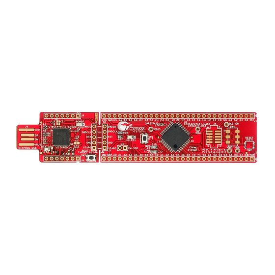
Hardware Figure 4-4. PSoC 4 M-Series Prototyping Kit Broken into Two Parts 4.2.5 Header Connections The PSoC 4 M-Series Prototyping Kit supports a number of unpopulated headers on both the KitProg and the target PSoC 4 boards. 4.2.5.1 Functionality of J1 and J2 Headers (Target Board) The target board contains two, dual-inline, headers (J1 and J2). - Page 26 Hardware Table 4-1. J1 Header Pin Details Table 4-2. J2 Header Pin Details PSoC 4 M-Series Prototyping Kit GPIO PSoC 4 M-Series Prototyping Kit GPIO Signal Description Signal Description J2_01 VDDD Power J1_01 /XRES GPIO J2_02 Ground J1_02 P5[0] GPIO J2_03 P0[7] GPIO/SW (SW1)
- Page 27 Hardware Figure 4-6. J7 and J3 Headers Table 4-3. Pin Details of J7 Header Table 4-4. Pin Details of J3 Header PSoC 4 M-Series Prototyping Kit GPIO (J3) PSoC 5LP KitProg Header (J7) Signal Description Signal Description J7_01 VTARG Power J3_01 VTARG Power...
-
Page 28: User And Passive Inputs
Hardware Table 4-5. Pin Details of J9 Table 4-6. Pin Details of J8 PSoC 5LP to KitProg Header (J9) PSoC 5LP to KitProg Header (J8) Signal Description Signal Description J9_01 VBUS Power J8_01 Ground J9_02 Ground J8_02 P3.0 GPIO J9_03 P12.5 GPIO J8_03... - Page 29 Hardware Figure 4-9. Reset/Boot Button Reset Button The target board provides a footprint for a surface-mount switch, which can be used to reset the PSoC 4200M and EZ-BLE devices when the two boards are separated. Figure 4-10. Reset (RST) Button 4.2.6.3 LEDs The PSoC 4 M-Series Prototyping kit contains three LEDs:...
-
Page 30: Ez-Ble Proc Module
Module. The EZ-BLE PRoC Module is a fully integrated, 10×10×1.8 mm, fully certified, programmable module designed for ease-of-use and reduced time-to-market. It contains Cypress’s PRoC BLE chip, two crystals, chip antenna, shield, and passive components. Refer to AN96841 - Getting Started With EZ-BLE PRoC Module more details. - Page 31 Hardware Figure 4-15. EZ-BLE Connections The EZ-BLE module includes the following connections to the PSoC 4200M and KitProg: UART connections to PSoC 4200M through zero-ohm resistors R28 and R27 (see Figure 4-16 ■ Table 4-7). C connections to KitProg and PSoC 4200M. See Table 4-7 for details.
- Page 32 Hardware 3. Remove the zero-ohms resistors R18 and R16 4. Move the DPDT switch to position A as shown in Figure 4-16 to program PSoC 4200M and to position B as shown in Figure 4-17 to program the EZ-BLE module Figure 4-16.
-
Page 33: Code Examples
Using the Kit Code Example Follow these steps to open and use the code example provided with the kit. 1. Launch PSoC Creator from Start > All Programs > Cypress > PSoC Creator<version> > PSoC Creator <version>. 2. On the Start Page, click CY8CKIT-043 under Examples and Kits > Kits. The code example... - Page 34 Code Examples Figure 5-1. Open Example Project from PSoC Creator 4. Build the example project by choosing Build > Build <Project Name>, as shown in Figure 5-2. A .hex file is generated after a successful build process. Figure 5-2. Build Example Project from PSoC Creator 5.
- Page 35 Code Examples Figure 5-3. Program Device in PSoC Creator 7. PSoC Creator opens the programming window if the device is not yet acquired. Select KitProg and click the Port Acquire button, as shown in Figure 5-4. Figure 5-4. Port Acquire 8.
- Page 36 Code Examples Figure 5-5. Connect Device From PSoC Creator and Program 9. Once programming is successful, the blue LED (LED1) on the board should start displaying the breathing effect at approximately 1-Hz rate. From the Workspace Explorer in PSoC Creator, open the CE97634 PSoC 4 Breathing LED.pdf as shown in Figure 5-6.
-
Page 37: Using Built-In Psoc Creator Code Examples With The Kit
Using Built-in PSoC Creator Code Examples with the Kit Follow these steps to open and use the built-in PSoC Creator examples. 1. Launch PSoC Creator from Start > All Programs > Cypress > PSoC Creator<version> > PSoC Creator <version>. 2. On the Start Page, click Find Example Project... under Examples and Kits, as shown in Figure 5-7. - Page 38 Code Examples Figure 5-8. Selecting PSoC 4200M Device Family in Find Examples Window 4. You can use any project that appears in the list with the kit. As an example, we will select the ADC_SAR_Seq_DieTemp_PSoC4 project and see how to use it with CY8CKIT-043. 5.
- Page 39 Code Examples Figure 5-9. ADC_SAR_Seq_DieTemp_PSoC4 Code Example 6. This example project measures an input voltage in the range 0 to 1.024 V on a pin and sends the measured voltage and device die temperature over UART. In addition, the project controls the brightness of an LED using a PWM based on the value measured by the ADC.
- Page 40 Code Examples Figure 5-10. cydwr Settings for CY8CKIT-043 7. For CY8CKIT-043, make sure the device used is CY8C4247AZI-M485 as shown in Figure 5-11. Build the project and program the kit as explained in Using the Kit Code Example on page Figure 5-11.
- Page 41 Code Examples Figure 5-12. Project Datasheet: ADC_SAR_Seq_DieTemp_PSoC4 9. You can view the die temperature value and ADC measured voltage through any terminal emula- tor program like PuTTY or HyperTerminal. Refer to chapter 5 of the KitProg User Guide for details on how to configure and use the software with KitProg.
-
Page 42: Appendix
ASSY DRW: 620-60255-01 NO LOAD NO LOAD NO LOAD No Load 330 OHM @ 100MHz Reset Button CYPRESS SEMICONDUCTOR © 2015 CYPRESS SEMICONDUCTOR © 2015 CYPRESS SEMICONDUCTOR © 2015 Title Title Title CY8CKIT-043 PSoC 4 M-Series Prototyping Kit CY8CKIT-043 PSoC 4 M-Series Prototyping Kit... - Page 43 PTC Resettable Fuse KitProg I/O Headers KP_P12_4 RESET KP_P12_3 SWDCLK KP_P12_2 SWDIO HDR 1x5 VBUS PCA: 121-60220-01 CYPRESS SEMICONDUCTOR © 2015 CYPRESS SEMICONDUCTOR © 2015 CYPRESS SEMICONDUCTOR © 2015 KP_DM 0.1 uF No Load PCB: 600-60250-01 KP_DP 0402 Title Title...
-
Page 44: Programming The Psoc 4 M-Series Prototyping Kit Using Miniprog3/Kitprog
Figure A-1. Connecting CY8CKIT-043 to MiniProg3 Note: CY8CKIT-002 MiniProg3 is not part of the PSoC 4 M-Series Prototyping kit contents and can be purchased from the Cypress Online Store. CY8CKIT-043 PSoC® 4 M-Series Prototyping Kit Guide, Doc. #: 001-97606 Rev. **... -
Page 45: Bill Of Materials
Item Qty Reference Value Description Manufacturer Mfr Part Number PCB, 112 mm x 24.13 600-60250-01 mm, High Tg, ENIG fin- Cypress Semicon- 600-60250-01 REV03 ish, 2 layer, Color = RED, ductor Silk = WHITE C1,C4,C5,C6,C8,C 11,C14,C18,C19,C CAP CER 0.1UF 10V 10% C1005X5R1A104K050 0.1 uFd... - Page 46 0603 SMD SW PUSH- SWITCH TACTILE SPST- SW1,SW3 C&K Components KMR221GLFS BUTTON NO 0.05A 32V 68QFN PSoC 5LP chip for Cypress Semicon- PSoC 5LP USB debug channel and CY8C5868LTI-LP039 ductor USB-Serial interface Cypress Semicon- PSoC 4200M 68TQFP PSoC 4M CY8C4247AZI-M485...
-
Page 47: Revision History
Revision History ® CY8CKIT-043 PSoC 4 M-Series Prototyping Kit Guide Revision History Document Title: CY8CKIT-043 PSoC® 4 M-Series Prototyping Kit Guide Document Number: 001-97606 Origin of Revision Issue Date Description of Change Change 06/25/2015 MSUR New kit guide CY8CKIT-043 PSoC® 4 M-Series Prototyping Kit Guide, Doc. #: 001-97606 Rev. **...
Need help?
Do you have a question about the PSoC 4 M Series and is the answer not in the manual?
Questions and answers