Table of Contents

Subscribe to Our Youtube Channel
Related Manuals for Cypress CY8CKIT-041-41XX


Summary of Contents for Cypress CY8CKIT-041-41XX
- Page 1 CY8CKIT-041-41XX ® PSoC 4100S Pioneer Kit Guide Doc. # 002-14067 Rev. *C Cypress Semiconductor 198 Champion Court San Jose, CA 95134-1709 Phone (USA): 800.858.1810 Phone (Intnl): +1.408.943.2600 www.cypress.com Arrow.com. Downloaded from...
- Page 2 Cypress is not liable, in whole or in part, and Company shall and hereby does release Cypress from any claim, damage, or other liability arising from or related to all Unintended Uses of Cypress products.
-
Page 3: Table Of Contents
Contents Safety Information 1. Introduction Kit Contents .........................5 Board Details .......................6 PSoC Creator ......................11 Getting Started......................14 Additional Learning Resources..................14 Technical Support......................15 Documentation Conventions..................15 Acronyms........................15 2. Software Installation Before You Begin.......................17 Install Software ......................17 Uninstall Software......................19 3. Kit Operation Theory of Operation....................20 KitProg2 ........................29 4. -
Page 4: Safety Information
General Safety Instructions ESD Protection ESD can damage boards and associated components. Cypress recommends that you perform procedures only at an ESD workstation. If an ESD workstation is not available, use appropriate ESD protection by wearing an antistatic wrist strap attached to a grounded metal object. -
Page 5: Introduction
This kit supports operating voltages of 1.9 V, 3 V (battery), 3.3 V ,or 5 V. You will use PSoC Creator™ to develop and debug the PSoC 4100S device projects. PSoC Creator is Cypress’s standard integrated design environment (IDE). If you are new to PSoC Creator, see the documentation on the PSoC Creator webpage. -
Page 6: Board Details
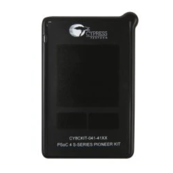
Introduction Figure 1-1. Kit Contents Inspect the contents of the kit; if you find any part missing, contact your nearest Cypress sales office for help: www.cypress.com/support. Board Details As shown in Figure 1-2, the PSoC 4100S Pioneer Kit features a CapSense trackpad, two CapSense buttons, and a proximity sensor loop (not visible on the case) that allows you to evaluate Cypress’s... - Page 7 Introduction Figure 1-2. PSoC 4100S Pioneer Kit 4. Potentiometer 1. KitProg2 Status LEDs 2. Power LED 5. Reset button 6. User button 3. KitProg2 USB Micro-B connector 7. KitProg2 user button PSoC® 4100S Pioneer Kit Guide, Doc. # 002-14067 Rev. *C Arrow.com.
- Page 8 Introduction Figure 1-3. PSoC 4100S Pioneer Kit without Overlay 1. CapSense trackpad 2. CapSense buttons 3. Proximity sensor loop Note: The above figure shows the kit without color gamut overlay PSoC® 4100S Pioneer Kit Guide, Doc. # 002-14067 Rev. *C Arrow.com.
- Page 9 10. Arduino compatible power and I/O headers 24. PSoC 4100S (CY8C4146AZI-S433, U1) 11. 32.768 kHz crystal oscillator (Y1) selection switch (SW5) 13. Cypress F-RAM 1Mb (FM24V10-G, U11) (CY8C5868LTI-LP039, U15) PSoC® 4100S Pioneer Kit Guide, Doc. # 002-14067 Rev. *C Arrow.com. Arrow.com.
- Page 10 Introduction Figure 1-5. PSoC 4100S Pioneer Board (Bottom View) 27. FPC connector Figure 1-6. PSoC 4100S Pioneer Board Pinout P5LP_VDD P5LP0_1 P5LP15_1 P5LP15_2 P5LP12_0 P5LP15_3 P5LP3_0 P5LP12_5 P5LP12_1 P5LP3_4 P5LP3_5 P5LP12_7 P5LP12_6 P5LP3_6 Arduino Uno R3 PSoC 4100S Pioneer Kit PSoC®...
-
Page 11: Psoc Creator
Figure 1-7. PSoC Creator Features PSoC Creator also enables you to tap into an entire tool ecosystem with integrated compiler chains and production programmers for PSoC devices. For more information, visit www.cypress.com/psoccreator. PSoC® 4100S Pioneer Kit Guide, Doc. # 002-14067 Rev. *C Arrow.com. - Page 12 Introduction 1.3.1 PSoC Creator Code Examples PSoC Creator includes a large number of code examples. These examples are accessible from the PSoC Creator Start Page, as shown in Figure 1-8. Code examples can speed up your design process by starting you off with a complete design. The code examples also show how to use PSoC Creator Components for various applications.
- Page 13 Introduction Figure 1-9. Code Example with Sample Code 1.3.2 Kit Code Examples You can access the installed kit code examples from the PSoC Creator Start Page. To access these examples, expand the Kits under the section Examples and Kits; then, expand the specific kit to see the code examples.
-
Page 14: Getting Started
F-RAM, method to use the on board EZ-BLE PRoC Module, kit schematics, and the bill of mate- rials (BOM). Additional Learning Resources Cypress provides a wealth of data at www.cypress.com to help you to select the right PSoC device for your design, and to help you to quickly and effectively integrate the device into your design. For a... -
Page 15: Technical Support
Introduction Technical Support For assistance, visit Cypress Support or contact customer support at +1(800) 541-4736 Ext. 2 (in the USA) or +1 (408) 943-2600 Ext. 2 (International). You can also use the following support resources if you need quick assistance: Self-help (Technical Documents) ■... - Page 16 Introduction Table 1-3. Acronyms Used in this Document (continued) Acronym Definition human interface device inter-integrated circuit integrated circuit ICSP in-circuit serial programming IDAC current output digital-to-analog converter integrated design environment light-emitting diode personal computer programmable gain amplifier positive temperature coefficient PRoC Programmable Radio-on-Chip PSoC...
-
Page 17: Software Installation
Before You Begin To install Cypress software, you will require administrator privileges. However, they are not required to run software that is already installed. Before you install the kit software, close any other Cypress software that is currently running. Install Software Follow these steps to install the PSoC 4100S Pioneer Kit software: 1. - Page 18 Software Installation 3. Click Install CY8CKIT-041-41XX to start the PSoC 4100S Pioneer Kit installation, as shown in Figure 2-1. Figure 2-1. Kit Installer Screen 4. Select the folder in which you want to install the PSoC 4100S Pioneer Kit-related files. Choose the directory and click Next.
-
Page 19: Uninstall Software
Uninstall Software The software can be uninstalled using one of the following methods: Go to Start > All Programs > Cypress > Cypress Update Manager and select the Uninstall ■ button that corresponds to the kit software. -
Page 20: Kit Operation
Kit Operation This chapter introduces you to the various features of the PSoC 4100S Pioneer Kit, including the theory of operation and the onboard programming and debugging functionality, and the KitProg2 USB-UART and USB-I2C bridges. Theory of Operation The PSoC 4100S Pioneer Kit is built around the PSoC 4100S device. Figure 3-1 shows the block diagram of the PSoC 4100S device. - Page 21 Kit Operation ® ® 48-MHz ARM Cortex -M0+ CPU ❐ Up to 64KB flash, 8KB SRAM ❐ Real-time clock capability with a WCO ❐ Programmable Analog Blocks ■ One 12-bit, 1-Msps SAR ADC ❐ One 10-bit, 46.8-Ksps Single-Slope ADC ❐ Two opamps configurable as PGAs, comparators, etc.
- Page 22 Kit Operation The PSoC 4100S Pioneer Kit comes with a case that has the PSoC 4100S Pioneer board (main board) and a Flex PCB. Refer to How to Open the Kit Case on page 26 for details on opening the case.
- Page 23 10. Arduino compatible power and I/O headers 24. PSoC 4100S (CY8C4146AZI-S433, U1) 11. 32.768 kHz crystal oscillator (Y1) selection switch (SW5) 13. Cypress F-RAM 1Mb (FM24V10-G, U11) (CY8C5868LTI-LP039, U15) PSoC® 4100S Pioneer Kit Guide, Doc. # 002-14067 Rev. *C Arrow.com. Arrow.com.
- Page 24 3 V from the rechargeable battery. The kit has an onboard two- channel regulator from Cypress that provides 3.3 V on one channel and 1.9 V on the other. 3 V is derived from the onboard battery and 5 V from the USB.
- Page 25 F-RAM and the PSoC 4100S. 13.Cypress F-RAM (U11): This kit features a Cypress F-RAM device (FM24V10-G) of 1 Mb capac- ity. The F-RAM is connected to the I2C interface of the PSoC 4100S. The F-RAM device can be used similar to an external EEPROM memory for data logging operations.
- Page 26 Kit Operation 3.1.1 How to Open the Kit Case The kit comes with a case that houses an FR4 board called the PSoC 4100S Pioneer board (main board) and a Flex PCB. The following steps show how to open the case. 1.
- Page 27 Kit Operation 3. Hold the kit as shown in Figure 3-8 and pull the bottom side of the casing wall outwards. Hold the USB connector and lift the board gently. Figure 3-8. Pull the Main Board from the Case Note that the main board needs to be removed slowly because it is connected to the Flex PCB. Flex PCB is permanently attached to the top case.
- Page 28 Kit Operation 3.1.3 Reassembling Kit Case 1. Connect the Flex PCB to the main board. 2. Flip the main board and gently push the Flex PCB under the main board. 3. Align the main board switches with respective slots on the top case. 4.
-
Page 29: Kitprog2
USB-UART bridge. The PSoC 4100S Pioneer Kit also supports mass storage programming using KitProg2. A Cypress PSoC 5LP device is used to implement the KitProg2 functionality. The KitProg2 is integrated in most PSoC development kits. For more details on the KitProg2 functionality, refer to the KitProg2 User Guide available in the following path in the kit installation directory: <Install_Directory>\CY8CKIT-041-41XX PSoC 4100S Pioneer Kit\<version>\... - Page 30 Kit Operation Figure 3-12. Connect USB Cable to USB Connector on the Kit 2. Open the desired project in PSoC Creator by selecting File > Open > Project/Workspace. This provides the option to browse and open your saved project. 3. Select Build > Build Project or press [Shift] [F6] to build the project. 4.
- Page 31 Kit Operation 3.2.4 Mass Storage Programmer The KitProg2 in the PSoC 4100S Pioneer Kit supports programming through a USB Mass Storage interface. This interface allows you to program the PSoC 4100S by copying .hex files into an emu- lated USB Mass Storage device. For more details on KitProg2 Mass Storage Programmer, refer to KitProg2 User Guide.
-
Page 32: Code Examples
1. Launch PSoC Creator from Start > All Programs > Cypress > PSoC Creator <version> > PSoC Creator <version>. 2. On the Start Page, click CY8CKIT-041-41XX under Examples and Kits > Kits. A list of code examples appears, as shown in Figure 4-1. - Page 33 Code Examples 5. Connect PSoC 4100S Pioneer Kit to the PC using the USB cable, as shown in Figure 3-12, to program the kit with the code example. 6. Choose Debug > Program in PSoC Creator. 7. If the device is already acquired, programming will complete automatically – the result will appear in the PSoC Creator status bar at the bottom left side of the screen.
-
Page 34: Code Examples
Table 4-1. Code Examples in PSoC Creator Project Title/Description This code example implements two CapSense buttons using CY8CKIT-041-41XX. The left button is used to control the onboard RGB LED color, and the right button is used to control the brightness CE214022 LP CapSense Buttons of the RGB LED. - Page 35 Code Examples All code examples have an associated PDF document containing the project details, which can be accessed from the PSoC Creator as shown in the Figure 4-4. Please refer to the respective code example document for more details on the functionality and implementation. Figure 4-4.
-
Page 36: Appendix
Appendix Schematics Refer to the schematics files available in the kit installation directory under following paths: <Install_Directory>\CY8CKIT-041-41XX PSoC 4100S Pioneer Kit\<version>\ ■ Hardware\CY8CKIT-041-41XX Schematic.pdf <Install_Directory>\CY8CKIT-041-41XX PSoC 4100S Pioneer Kit\<version>\ ■ Hardware\CY8CKIT-041-41XX Flex Schematic.pdf Hardware Functional Description This section provides details on the individual hardware blocks of the PSoC 4100S Pioneer Kit. - Page 37 EZ-BLE PRoC Module, when powered from USB port or external power supply. The voltage selection is made through switch SW6. The voltage regulator (MB39C011A) from Cypress has two channels and generates a constant 3.3 V on one channel and 1.9 V on the other. The onboard rechargeable battery provides 3 V to the kit.
- Page 38 Figure A-2. Schematics of Voltage Regulator Circuit and Power Selection Switch LED4 VO_V3.3 Input Voltage Range 6-12V R121 R124 0805 560 ohm 15.6K AMBER LED R122 Power LED P5LP2_7 6.8K 1 nF 820 ohm 5% Zener 3.3V 0.1 uF 910 ohm 1% 18K 1% 0.1 uF 18K 1%...
- Page 39 A.2.5 Battery Charging Circuit The 3.3 V generated by the regulator is also used to charge the battery as shown in Figure A-3. Note that the battery charging time is not optimal if the battery is discharged below 2.2 V (dead threshold).
- Page 40 Figure A-5. Schematics of Current Measurement Switch VTARG NO LOAD SW 7 ZERO P4_VDD P4_VDD 0.86 Ohm 9.76 Ohm NO LOAD ZERO 5 POLE DIP SW SWITCH(S7) SETTINGS Load Default Note: To avoid leakage OFF OFF OFF OFF (short) during battery operation remove R20 1 ohm OFF OFF...
- Page 41 Figure A-7. Potentiometer Schematics P4_VDD R118 ZERO R133 P2_4 1 nF ZERO R125 J2_P2_4 ZERO Potentiometer NO LOAD Remove R118, while performing low power measurement. Note that there is a current leakage of 80 µA on the VTARG node into the PSoC 5LP when using battery (VBAT) as the power supply.
- Page 42 marily a digital port that contains I/O pins for PWM, I2C, SPI, and analog reference. The J4 header is also a digital port that contains I/O pins for UART and PWM. The J12 header is an Arduino ICSP- compatible header for the SPI interface and is not populated. Most of the pins available on J2, J3, and J4 headers have multiplexed functionalities such as CapSense sensors, user switch, or RGB LEDs.
- Page 43 (active low). A.2.13 Cypress Ferroelectric RAM (F-RAM) The PSoC 4100S Pioneer Kit contains an F-RAM device (FM24V10-G) that can be accessed through I2C lines P3 [0] and P3 [1] of the PSoC 4100S. The F-RAM has a capacity of 1-Mbit (128 KB) with an I2C speed up to 3.4 MHz.
-
Page 44: Using The Fm24V10 F-Ram
It contains Cypress’s PRoC BLE device, two crystals, chip antenna, shield, and passive components. For more information on using the EZ-BLE PRoC module, see Using EZ- BLE PRoC Module on page A.2.15 External Crystals The PSoC 4100S Pioneer Kit includes a 32.768-kHz (Y1) external crystal for the WCO input. The WCO is used to provide an accurate low-frequency clock to PSoC 4100S for Deep-Sleep wake up intervals, and WDT reset intervals. - Page 45 Figure A-10. F-RAM I2C Data Format for HS Mode A.3.3 Write/Read Operation The F-RAM device datasheet includes details on how to perform a write/read operation with the F- RAM. Figure A-11 Figure A-12 provide a snapshot of the write/read packet structure as a quick reference.
-
Page 46: Using Ez-Ble Proc Module
EZ-BLE PRoC Module and PSoC Cre- ator, the development tool used for all EZ-BLE modules. This application note also guides you to more resources to accelerate in-depth learning about the Cypress EZ-BLE solutions. Visit www.cypress.com/ez-bleprocmodule/ for additional information on the EZ-BLE PRoC Module. - Page 47 C connections to KitProg2 and PSoC 4100S. See Table A-1 for details. ■ SWD connections to KitProg2 through switch SW5. The SWD connections are shared between ■ the PSoC 4100S and EZ-BLE PRoC Module. The connections between EZ-BLE PRoC Module and PSoC 4100S are shown in Figure A-13 Figure A-13.
-
Page 48: Migrating Projects Across Different Pioneer Series Kits
Migrating Projects Across Different Pioneer Series Kits All Cypress Pioneer series kits are Arduino Uno-compatible and have some common onboard peripherals such as RGB LED, CapSense, and user switch. However, the pin mapping in each of the boards is different due to differences in pin functions of the PSoC device used. This section lists the pin mapping of the Pioneer series kits to allow for easy migration of projects across different kits. - Page 49 A.5.1 Arduino Uno Compatible Headers Table A-2. J1 Arduino Compatible Header Pin Map Pioneer Series Kits CY8CKIT- Arduino Pin CY8CKIT- CY8CKIT- CY8CKIT- CY8CKIT- CY8CKIT- 041-40XX/ CY8CKIT- 042-BLE CY8CKIT- 041-41XX V5.0 V5.0 V5.0 V5.0 V5.0 V5.0 V5.0 3.3V V3.3 V3.3 V3.3 V3.3 V3.3 V3.3...
- Page 50 Table A-4. J3 Arduino Compatible Header Pin Map Pioneer Series Kits CY8CKIT- Arduino Pin CY8CKIT- CY8CKIT- CY8CKIT- CY8CKIT- CY8CKIT- 041-40XX/ CY8CKIT- 042-BLE CY8CKIT- 041-41XX P2[6] P1[4] P0[5] P0[2] P0[2] P0[3] P2[4] P3[6] P1[5] P0[4] P0[3] P0[3] P2[7] P1[7] P3[4] P1[6] P0[2] P2[7] P6[3]...
- Page 51 P0[2] P3[5] Note 1: CMOD1, and CTANK1 are available only in the CY8CKIT-046 PSoC 4 L-Series Pioneer Kit. Note 2: CintA and CintB are available only in the CY8CKIT-041-40XX and CY8CKIT-041-41XX. Table A-7. Proximity Header Pin Map Pioneer Series Kits...
-
Page 52: Bill Of Materials
P0[7] P0[7] P0[7] P0[3] Bill of Materials Refer to the BOM files in the following paths in the kit software installed: <Install_Directory>\CY8CKIT-041-41XX PSoC 4100S Pioneer Kit\<ver- ■ sion>\Hardware\CY8CKIT-041-41XX PCBA BOM.xlsx <Install_Directory>\CY8CKIT-041-41XX PSoC 4100S Pioneer Kit\<ver- ■ sion>\Hardware\CY8CKIT-041-41XX Flex PCBA BOM.xlsx PSoC®... -
Page 53: Revision History
Revision History CY8CKIT-041-41XX PSoC® 4100S Pioneer Kit Guide Revision History Document Title: CY8CKIT-041-41XX PSoC® 4100S Pioneer Kit Guide Document Number: 002-14067 Origin of Revision Issue Date Description of Change Number Change 5361817 07/20/2016 SRDS New kit guide. 5401322 08/12/2016 SRDS... - Page 54 Index CY8CKIT-041-41XX PSoC® 4100S Pioneer Kit Guide Revision History (continued) Document Title: CY8CKIT-041-41XX PSoC® 4100S Pioneer Kit Guide Document Number: 002-14067 Origin of Revision Issue Date Description of Change Number Change 5444290 09/21/2016 SRDS Updated Introduction chapter on page Updated “Board Details”...
Need help?
Do you have a question about the CY8CKIT-041-41XX and is the answer not in the manual?
Questions and answers