Rinnai RHFE1000 Installation Manual
Linear collection gas fireplaces
Hide thumbs
Also See for RHFE1000:
- Installation manual (38 pages) ,
- Installation manual (40 pages) ,
- Operation manual (20 pages)

Related Manuals for Rinnai RHFE1000


Summary of Contents for Rinnai RHFE1000
- Page 1 Models: RHFE0800, RHFE1000, RHFE1500 Linear collection gas fireplaces Installation guide...
- Page 2 Important Appliance must be installed with a Rinnai approved flue system. This appliance shall be installed in accordance with: - Manufacturer’s installation instructions Current: - AS/NZS 5601 Gas Installations - AS/NZS 5263 Gas Appliances General Requirements - AS/NZS 3000 Electrical Standards...
-
Page 3: Table Of Contents
Contents Before you start ............4 Specification ............5 Unit dimensions (mm)...........6 Clearances from combustibles ......7 Hearths ..............9 TV installation ............10 Installation overview ..........11 Cavity ventilation ..........12 Framing dimensions ..........13 Gas supply............17 Room thermistor ...........17 Electrical supply............18 Flue terminal position ...........18 Installing the Linear into the cavity .......19 Removing the glass front ........20 Commissioning .............21 Wiring diagram .............25... -
Page 4: Before You Start
Before you start Unpack the appliance and components and check for damage. DO NOT install any damaged items. Check all components have been supplied, refer table below, and that you have the correct gas type. Read these instructions to get an overview of the steps required before starting the installation. Failure to follow these instructions could cause a malfunction of the appliance. -
Page 5: Specification
Specification Inbuilt power flued convection fan fire operated by a simple infra-red remote, or by the Rinnai Wi-Fi app that allows full thermostatic control as well as other features such as timers. Different burn media options available. Specification summary 800/1000... -
Page 6: Unit Dimensions (Mm)
Unit dimensions (mm) IMPORTANT • These are the unit dimensions only, not the framing/cavity dimensions, refer p.14-16 • The centre of the glass is NOT the centre of the appliance • Depth dimension is the same for all models 425 min. singled sided 425 face-to-face double sided... -
Page 7: Clearances From Combustibles
Clearances from combustibles The clearances listed below, measured from the edge of the glass, are minimum clearances unless otherwise stated. While the heater is operating The appliance must not be installed where curtains or other combustible materials could come into contact with the fire. The 400 mm side clearance includes side walls. - Page 8 The below diagrams are to assist in determining the full clearance area around the Linear. 1600 257 ± 5* * Adjustable Clearance Glass width Clearance firebox feet 1800 257 ± 5* 1000 * Adjustable Clearance Glass width Clearance firebox feet 2300 257 ±...
-
Page 9: Hearths
Hearths Any hearth that is installed in the shaded area (shown below) must be capable of withstanding temperatures up to 100 °C. Some laminated materials may buckle or delaminate when exposed to high levels of heat. 1. A 3 mm air gap between the hearth and lower fire lip is critical. This allows for air flow to critical components and for correct operation of the IR receiver. -
Page 10: Tv Installation
It is up to the owner to check the TV installation with the TV manufacturer—some have warranty conditions that state a TV is not to be installed above a fireplace. Rinnai does not accept any responsibility for damage to a TV resulting from the use of this information. -
Page 11: Installation Overview
Installation overview Complete framing and base panel, p.12-16. Prepare gas and electrical connections, and cavity ventilation. Fit the Linear Move the Linear into the cavity. Tip forward slightly to get the two back feet in first. To reduce the weight you can remove the glass first (p.20). The Linear as adjustable feet on all corners. Use these feet to level the fire. -
Page 12: Cavity Ventilation
Cavity ventilation Ventilation of at least 2000 mm is recommended in the cavity, ideally below the base of the fire. This is to provide room air at ambient room temperature to the fire thermistor located in the base of the fire . -
Page 13: Framing Dimensions
Framing dimensions The framing dimensions have the studs offset. This is because the cavity needs to be framed based on the centreline of the Linear glass, NOT the opening size. IMPORTANT Where there is a requirement for a symmetrical installation, the cavity size will need to increase. - Page 14 Linear 800 minimum framing dimensions (mm) The framing dimensions have the studs offset. This is because the cavity needs to be framed based on the centreline of the Linear glass, NOT the opening size. IMPORTANT Where there is a requirement for a symmetrical installation, the cavity size will need to increase, refer diagram below.
- Page 15 Linear 1000 minimum framing dimensions (mm) The framing dimensions have the studs offset. This is because the cavity needs to be framed based on the centreline of the Linear glass, NOT the opening size. IMPORTANT Where there is a requirement for a symmetrical installation, the cavity size will need to increase, refer diagram below.
- Page 16 Linear 1500 minimum framing dimensions (mm) The framing dimensions have the studs offset. This is because the cavity needs to be framed based on the centreline of the Linear glass, NOT the opening size. IMPORTANT Where there is a requirement for a symmetrical installation, the cavity size will need to increase, refer diagram below.
-
Page 17: Gas Supply
Gas supply Gas pipe sizing must consider the gas input to this appliance, as well as other gas appliances in the premises. The gas supply termination is inside the heater, and enters from the lower left hand side of the appliance. Once the gas connection is completed and checked for gas leaks lock the sliding plate in place to stop the... -
Page 18: Electrical Supply
The power cord passes through a slot in the front right hand side of the appliance, approximately 140 mm from the front of the unit. Rinnai recommend the heater be plugged into a 230 V, 10 A earthed power point. The power point must not be above the heater. -
Page 19: Installing The Linear Into The Cavity
Installing the Linear into the cavity Carry bar position, two carry bars Hand hold Using the handholds (white slots LHS and carry bars RHS), carefully lift and slide the Linear into the enclosure and position in place. Adjustable feet and seismic brackets Use the feet on all corners of the unit to adjust the fire so that it is level. -
Page 20: Removing The Glass Front
Removing the glass front The glass front sits in a narrow channel at the bottom of the fire and is held in place by glass retainer latches positioned at the top, either side of the unit (the 1500 model has an extra glass retainer latch in the center). -
Page 21: Commissioning
Commissioning Accessing the commissioning instructions installed in the bottom of the unit will not normally occur during installation, which is why the instructions are detailed in this guide. For servicing and maintenance the commissioning sheet is installed in a pouch inside the base panel of the appliance: •... - Page 22 Commissioning and setting the gas pressures for the Linear is done with the glass off and before the burn media is added. The exception is the 800 FlameTech. The burners and NOTE the two FlameTech logs need to be temporarily positioned on the aeration sleeves for commissioning.
- Page 23 Linear 800 and 1000 gas control Linear 1500 gas control (with the extra solenoid) Inlet pressure test point screw Pilot pressure test point screw Pilot pressure adjustment screw (manometer position) Main burner pressure test point screw Check the pressures against those printed on the data plate. If the data plate is not easily accessible use the figures in the tables below.
- Page 24 Gas pressure setting = main burner on low = main burner on high = all burners on low = all burners on high Sequence will vary slightly depending on the model: Linear 800, 1000: PL > PH Linear 1500: PL > PF > PA > PH Checking the supply pressure Setting the operating pressure 1.
-
Page 25: Wiring Diagram
Linear collection wiring diagram DIP SW gr/y AC 230-240V Notes: RHFE1500---- Model only gr/y RHFE800-F--- Model only gr/y 1 2 3 4 5 6 7 8 r bl 1 2 3 1 2 3 4 5 6 7 8 9 OH.TH2 r bk w 13 12 1110 9 8 7 6 5 4 3 2 1... -
Page 26: Burn Media Installation
There is also a colour burn media placement sheet attached to the glass frame. Make sure you have these before starting. We will be updating this guide a month or two after the Linear launch to include links to installation videos via Rinnai’s YouTube channel. -
Page 27: Test Operation And Lighting Sequence
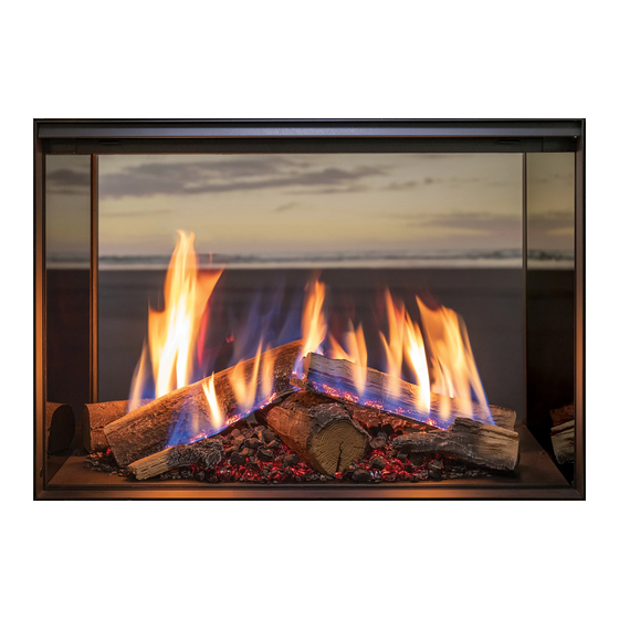
If the appliance cannot be made Linear 1000 modern media (glass) to perform correctly please contact Rinnai. Linear 1500 crushed glass is not shown, the flame pattern will be the same as the 1000 model shown. -
Page 28: Check Wi-Fi Connection
1. Wi-Fi module in the fire, once installed and has power connected, is on. 2. Homeowner downloads the Rinnai Wi-Fi app on their smart device. 3. Through the app, the Wi-Fi in the fire links (pairs) to the homeowners smart device. -
Page 29: Installing The Wall Lining
Installing the wall lining There are some aspects of the wall lining installation that are critical to the safe operation of the appliance. An air gap of at least 3 mm around the fire is critical to the safe operation of the Linear to ensure air flow in and around the unit. - Page 30 Below is an image to highlight the position and names of the different linear framing components. Adapt as necessary, depending on the wall lining being installed. Wallboard support rails (adjustable) Lips Finishing trim (accessory) A (1 : 3) IR receiver lens and harness Wi-Fi module assembly Glass retainer...
- Page 31 20 mm setting for Wallboard edge finished Lips combustible (not a Rinnai supplied part) Wallboard options Support Note: Wallboard support rails, the tabs for 10 mm and 13 mm boards need to be trimmed off as indicated. If not using the optional Outer...
- Page 32 Outer Finishing Trim latch A (1 : 1) Wallboard cutout A with optional Rinnai Outer Finishing Trim Outer Finishing Trim Cutout size C with 3 x 8 recess Cutout size B A (1:1)
- Page 33 Tiled or second skin wall linings (combustible and non-combustible options) No combustible materials within 50mm of top of fire Wall linings less than 20 mm may be combustible providing the wallboard support rails are left on. Back or support board MUST BE non-combustible below the timber lintel line if the wallboard Adhesive or...
- Page 34 Non-combustible thick wall linings No combustible materials within 50mm of top of fire Adhesive or mechanical fixing Backing or support board With wallboard support removed or wall must be non-combustible lining protruding beyond the fire front the below timber lintel line wall lining must be non-combustible for at least 300 mm up wall Ensure clearance around...
- Page 35 Non-combustible recess installations No combustible materials within 50mm of fire Front protruding panels flush with lips non-combustible lintel 50 mm Any materials within this area must be rated as non-combustible Front edge of lips Walls must not protrude beyond the front boundry line Opening size C minimum No combustible materials within 50mm of fire...
-
Page 36: General Flueing Guidelines
The vertical flue cowl Wall straps are included with some Rinnai should have a 500 mm clearance from any flue components. part of the building, refer image below. This... - Page 37 Flue sections located outside Sections of the flue located outside require the following precautions: • Only use PVC cement between the joints of the outer PVC pipes to secure and seal the joints against ingress of dust and water. • Only use non-acidic silicone sealant between the joints of the outer PVC pipe and any mating aluminium components to secure and seal these joints against ingress of dust and water.
-
Page 38: Flueing Options
ESWTERM LSFEXTKIT01 45° bends ESPIPE900 ESWTERM For lowest cost, optimal performance, ease of installation and servicing, Rinnai recommend short flue installations are considered before all other options. Maximum flue length and number of bends • Maximum flue length = 8.5 m •... - Page 39 Back direct and back extended flueing By changing the direction of the adaption flue position and connection, back direct and back direct extended flueing is possible. Flue components used: • Adaption flue (LSFKIT01) • Flue pipes (ESPIPE900) for extended flueing •...
- Page 40 Flueing options side direct, side extended, side and back flueing 300 mm minimum of straight flue is required before any bends (achieved with the ASPDFK and the flue transition extension—LSFEXTKIT01). This is required due to heat produced IMPORTANT from the initial section of the flue. The first 500 mm of flue requires a 25 mm clearance to combustibles.
- Page 41 Flueing options down-and-out flueing The down and out flue allows for the adaption flue component to face downwards, and for the flue to run vertically through a hole in the floor, and then terminate horizontally outside—flue must terminate 300 mm above the ground.
- Page 42 Cutting the ASPDFK and ESPIPE900 to length Cutting the last component in the flue assembly may be required to achieve the required length. Cutting is also required at a wall penetration, refer next page. • The minimum length of the ASPDFK when measured from the back plate of the transition casting MUST NOT be less than 300 mm when joining to other components.
- Page 43 Wall terminal assembly Only the ASPDFK, and the ESPIPE900/ESWTERM can be used to create a wall terminal Cutting components at a wall penetration 3 0 0 m m 5 0 m m Min. ASPDFK 12 mm t o w a l l L e n g t h length 1 2 m m...
-
Page 44: Air Hose Connection
Air hose connection This step in the installation is critical. If the connections are not secured properly, products of combustion could disperse into the room being heated. WARNING The Linear comes with one end of the flexible air hose already connected to the Linear air inlet. Attach the other end of the air intake hose to the connection on the flue, either the ASPDFK or the LSFKIT01. -
Page 45: Linear Flue Components
Linear flue components... - Page 46 Linear flue components Adaption flue kit Linear Coaxial flue pipe 900 mm Vertical roof terminal Code: LSFKIT01 Code: ESPIPE900 Code: ESROOFCOWL Includes: Extension pipe used to construct Roof cowl and connecting pipe for • flue adaptor horizontal, vertical, and downwards termination of a vertical flue—can •...
- Page 47 Flue transition extension 45° flue bends (two bends in a kit) Code: LSFEXTKIT01 Code: ESBEND Flue transition extension, approx. Two 45° bends used to facilitate between horizontal, vertical, and downwards flueing. Two spacers are included. Can be used separately, or together as a 300 mm.
- Page 48 Rinnai.co.nz Tel: 0800 746 624 http://www.youtube.com/rinnainz Linear installation guide 13563-H http://facebook.com.rinnainz...
Need help?
Do you have a question about the RHFE1000 and is the answer not in the manual?
Questions and answers