Rinnai Linear Series Installation Manual
Hide thumbs
Also See for Linear Series:
- Operation manual (24 pages) ,
- Flue installation manual (20 pages)
Table of Contents
Advertisement
Quick Links
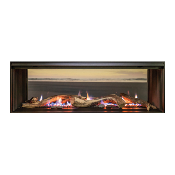
Installation guide
Linear collection
RHFE800S single sided
RHFE800D double sided
Installer please note
The Linear carton has a unit protection cutout that can be fixed to the appliance to protect
the fire from damage, debris, and dust, until final commissioning can be completed.
When completing the installation it is ideal to have the homeowner present to test
the Wi-Fi connectivity and correct operation of the fire.
RHFE1000S single sided
RHFE1000D double sided
RHFE1500S single sided
RHFE1500D double sided
Advertisement
Table of Contents


Need help?
Do you have a question about the Linear Series and is the answer not in the manual?
Questions and answers